Table of Contents
Many factors, some of which are not easily defined or described, must be considered in the design of a hydraulic backfill system. After participating in the design of several plants, I have a conviction that future refinements in sandfill systems must come in large part, from the merging of good design ideas and information from existing operating plants. It is important then, that we document and publish information on existing plant designs and their operating characteristics. This information will then be available for use by our successors and later innovators in hydraulic fill placement.
Pump Plant
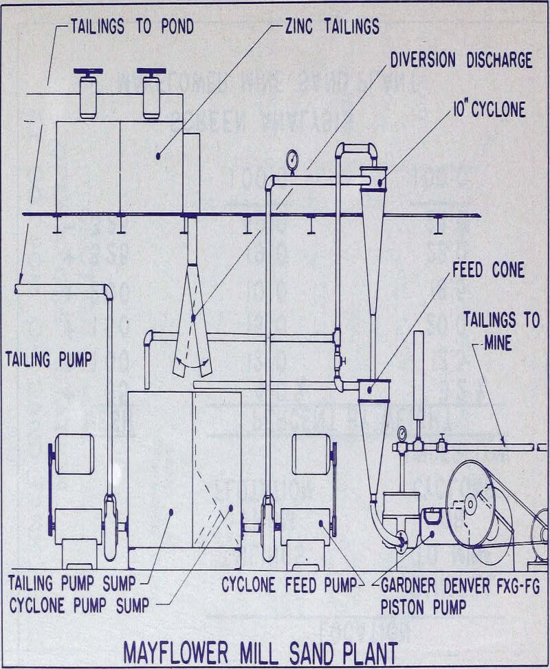
The pump selected for the Mayflower Plant is a Gardner-Denver 5×6 FXG-FG duplex power pump, fitted with 3-½ inch diameter pistons and liners. It is being operated at a main shaft speed of 56 rpm. The sand slurry described is being pumped into the mine at 48 to 51% solids. Dry solid density is approximately 3.0 grams per cubic centimeter. The fluid flow from the pump to the mine is approximately 55 gallons per minute and operates at a pump discharge pressure of 500 psi. The capacity of the system is 9.7 tons of solids per hour.
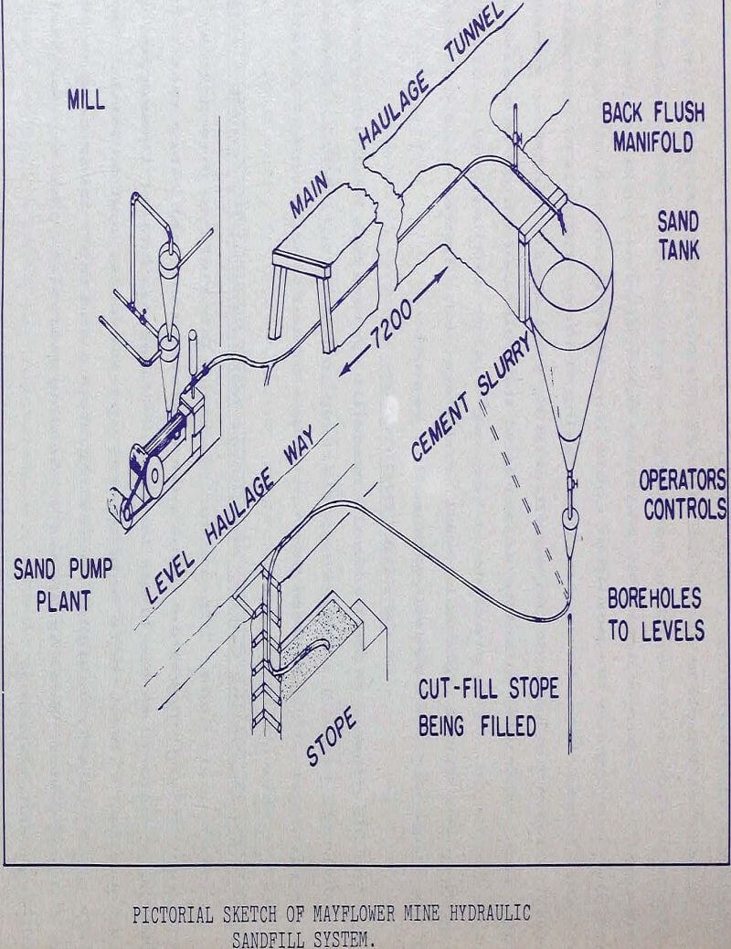
As indicated in our original Plant schematic, slurry is pumped into the mine thru 7,800 ft. of schedule 40 two inch pipe line. Slurry velocity is maintained at 5.3 ft. per sec. This slurry flow discharges into the sand tank located near the internal shaft collar.
Our experience over five years with this pipe line points up that any pump selected for slurry pumping should allow for a substantial increase in working pressures over the line’s expected life, due to the build-up of a hard black scale in the pipe line. When the pipe line was new, pipe line characteristics were 220 psi for clear water flow at 55 gallons per minute.
Sand Tank
The storage tank is a circular, unlined rock excavation below the haulage level near the interior shaft collar. The tank’s designed volume is intended to provide 24 hours storage of the slurry inflow from the mill since the mill operates on a 24 hour continuous basis. Intermediate storage permits discharge of the fill material into the stope fills on demand and a rate faster than sand is pumped in from the mill.
The planned volume of this tank was designed to be about 450 tons of sand solids. In practice, the live volume is actually about 250 tons due to an unexpectedly very steep angle of repose for the submerged, unagitated, semi-fluid sand fill material. While cleaning down the tank, sand has been observed to stand at 70° and steeper angles of repose up the walls of the tank. This accounts for a substantial portion of the tank excavation being dead storage. Attempts, short of mechanical agitation, have been made to activate larger portions of the tank. Elaborate spiders of spray rings were tried and were not very successful due to spray line discharge heads plugging up. This experience suggests that future designs should take into account this steep angle of repose. Greater live capacity for a given tank could be achieved by provisions for multi-point discharge.
Cement
At the Mayflower Mine, bulk cement from a 2,000 bag silo on the surface is trammed in special bulk hopper cars to a 200 bag storage silo near the sand tank. Because of plant layout, it is impossible to add dry cement directly into the fill distribution cone below the sand tank. To accomplish the addition of cement, bulk cement from the 200 bag silo is first slurried, then transported and mixed at a lateral pipe line connection with the fill stream below the tank.


