Table of Contents
The main opening is usually a permanent one that will be utilized throughout the life of the mine. It should, therefore, be so situated relative to the ore bodies that it will not be disturbed by ground movement caused by ore extraction and with a view to low maintenance cost.
It is advantageous, other things being equal, to locate the main opening centrally with regard to the ore bodies so that underground transportation may be as economical as possible. A central location is not always possible because of the surface topography or the rake or pitch of the ore body. Thus, the topography may be such that construction of a surface plant near the main opening would not be feasible in a central location or that transportation of ore to the mill would be unduly expensive. The deepest ore may be at one end of the deposit, and in some instances it may outcrop at one end and plunge toward the other end, and the shaft obviously should be located nearer the deepest ore to avoid having to drive long haulage- ways in waste rock and sink auxiliary underground winzes or inclines.
The adequacy of existing exploratory openings for ore extraction should be considered, and naturally these should be utilized when it is practicable to do so.
The best position for the main opening should then be determined from a consideration of the topography, the position of the mill site or point of loading ore for shipment, the feasibility of constructing a surface plant consisting of hoist house, shops, change house, and other buildings near the opening, the “center of gravity” of the known ore, both in plan and vertically, the position of the deepest ore, and the position and adequacy of existing openings.
Shafts VS Adits
In areas of low relief, where most of the ore lies below surface- drainage levels, it is apparent that the deposits must be developed by shafts. In areas of high relief, where much of the deposit lies above surface drainage, there is often a choice between shaft and adit development, and the option selected may be influenced by a number of considerations. The surface topography may preclude sinking a shaft near the deposit, or the only mill site available may be so situated that an adit is indicated immediately.
The cost per foot of shaft sinking may be several times that for driving an adit, the ratio in any given case depending on the cross-sectional area of the shaft or adit, the strength and nature of the ground, the amount of water to be handled, and the cost of power for hoisting and pumping. The plant-installation cost for shaft sinking is usually considerably greater than for a tunnel, since hoisting equipment, headframe, and pumping equipment must be provided. This greater investment for equipment may be several times the extra cost of track and cars required for adit development.
A very important consideration is the amount of water that will have to be handled. This becomes increasingly important in a mine with a long life expectancy, because pumping charges in a shaft mine go on year after year. The power required for pumping increases directly with the volume of water and height of lift.
A tunnel or adit drains the workings above it by gravity flow; and even though the workings may later be extended below the adit level by means of an inside shaft, it frequently happens that most of the water enters the mine at the upper levels and the lower levels are quite dry. In any event, the height to which water from lower levels must be lifted is reduced. The expense of hoisting ore and waste, caging cars or loading skips, and handling men and supplies in shafts comprise an appreciable operating-cost item.
On the other hand, adit development may involve driving headings, the excessive length of which may more than offset the additional costs for shaft sinking and shaft operation.
With shaft development, it is almost universally the practice to sink, develop, and start stoping in stages of one or a few levels at a time as new ore faces are required to maintain production and as ore continuity at greater depth is proved or indicated.
With adit development, a similar plan may be followed by driving a number of successively longer adits at successively lower elevations. When these can be driven on the vein instead of across the strike, development by this method has obvious advantages. When they must be driven in waste, the time involved in reaching the ore, the cost of so much dead work, and the uncertainties regarding persistence of the ore bodies at horizons corresponding to the elevations of the adits may minimize or eliminate entirely the advantages of adit development.
These and other factors that may be peculiar to a given deposit must be weighed against each other.
Inclined VS Vertical shafts
As far as shaft operations per se are concerned, vertical shafts usually are preferred to inclined shafts. Inclined shafts must be longer to reach the same depth, hoisting speed is ordinarily slower, wear on hoisting ropes is greater, and there are usually rope idlers to install and keep in repair. In bad ground, vertical shafts usually are easier to maintain.
An inclined shaft may be more economical where first cost of development and speed with which the mine can be brought into production more than offset the operating economies effected by vertical shaft development. An incline in the foot or hanging wall (usually the former) can be driven approximately parallel to the plane of the lode, so that only short crosscuts are required on each level to reach the ore body. The flatter the dip of the lode, the greater is the advantage of an inclined shaft. It is obvious that a vertical shaft started in the footwall of a dipping deposit is farther from the lode on each successively lower level, so that the time required for crosscutting to the lode and the cost thereof may be prohibitive on the lower levels. If a vertical shaft is started in the hanging wall, it will be nearer the lode on successively lower levels, until it finally crosses it; the crosscuts will then increase in length as the depth increases. A shaft in the hanging wall may be affected by subsidence, resulting in high operating and maintenance costs; or, if large pillars of ore are left unmined below the shaft for its protection, such ore may be tied up so that it cannot be recovered until the mine is almost worked out.
Sizes Of Main Openings
The size (cross-sectional dimensions) of a shaft or main haulage adit will be governed to a large extent by the anticipated rate of production. Minimum size limits are established by practical considerations even for very small production rates. Thus an adit should be large enough to pass the mine cars and leave room on the side for a ditch and for a man to pass a car. If animals are employed for haulage, the adit must be high enough for them to pass; and if electric trolley locomotives are to be used, the adit should be high enough to permit suspension of the trolley wires well above the head of a man standing upright. If the production rate is to be high, large cars and locomotives usually are most economical for haulage, and the adit must be big enough to accommodate them; in long adits it may be advisable to double-track the haulageway or at least to widen it in places to make room for passing tracks.
A shaft should be large enough to provide at least one compartment for hoisting ore and handling men, materials, and supplies and a separate compartment for a ladderway, air and water pipes, and electric cables.
In the Tri-State zinc and lead district one-compartment vertical shafts 5 by 7 or 6 by 6 feet in cross section are common and ore is hoisted in “cans” or buckets holding about 1,200 to 1,400 pounds of ore. Here, however, the ore lies at comparatively shallow depths and there are usually one or more “field” shafts in addition to the hoisting shaft, which are available for additional exits from the mine, for ventilation, and sometimes for the handling of men, materials, and supplies. Some of the newer shafts in this district employ cages or skips for hoisting and are 5 or 6 by 11 or 12 feet in cross section, or larger.
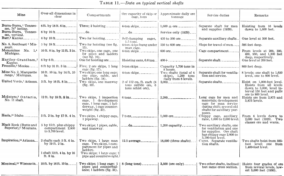
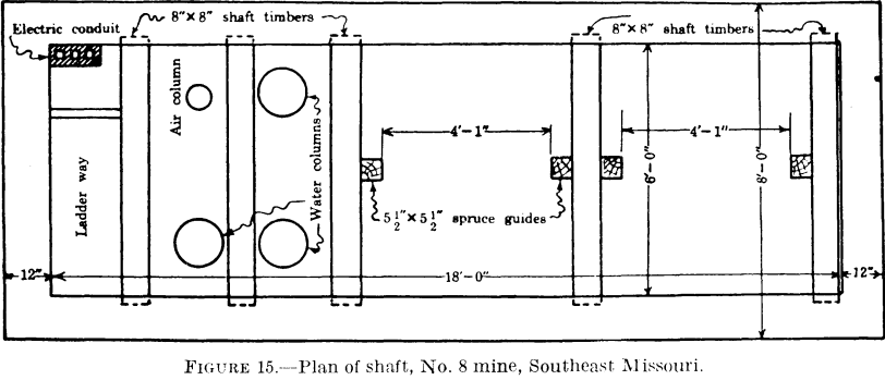
In the Southeast Missouri lead district vertical shafts are usually about 6 by 15 to 6 by 18 feet in the clear (inside timber) and are divided into three compartments, two of which are used for hoisting with skips in balance and the other for pipes and power cables. Generally, there are auxiliary shafts for ventilation and for handling men and supplies.
In the Western States the usual shaft for small or medium production, where ore is to be hoisted in balance in cars on cages or in skips to obtain the power economy of balanced hoisting, is rectangular and a minimum of 5 by 15 feet inside the timber or 7 by 17 feet outside the timber. This provides for two hoisting compartments each 5 by 5 feet in the clear and a ladderway pipeway 3 by 5 feet in the clear. Since the main operating shaft is often the main intake airway it should be of cross-sectional area great enough to pass at moderate velocities the amount of air required to ventilate the workings adequately. This is especially important in hot, deep mines. Sometimes auxiliary shafts are provided for intake or exhaust airways.
The first consideration in determining the size of a shaft is the duty to be required of it. This includes the hoisting of ore and waste and the hoisting and lowering of miners, timber, rails, explosives, drill steel and drilling equipment, and other materials and supplies. If the ore hoist also handles men and materials, the time available for hoisting ore obviously is reduced. The time required for these other duties depends on a number of factors. Thus, some mines use large amounts of timber for ground support, whereas others require very little; some use proportionately much greater quantities of drill steel than others; some shafts have to handle large quantities of waste for stope filling while others have little or no waste to handle. In some mines, especially those operating on a large number of levels, service demands for transferring bosses from one level to another and handling equipment consume a large amount of time. In such instances it is
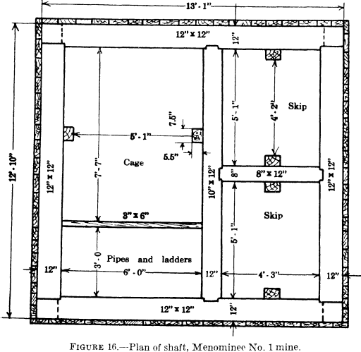
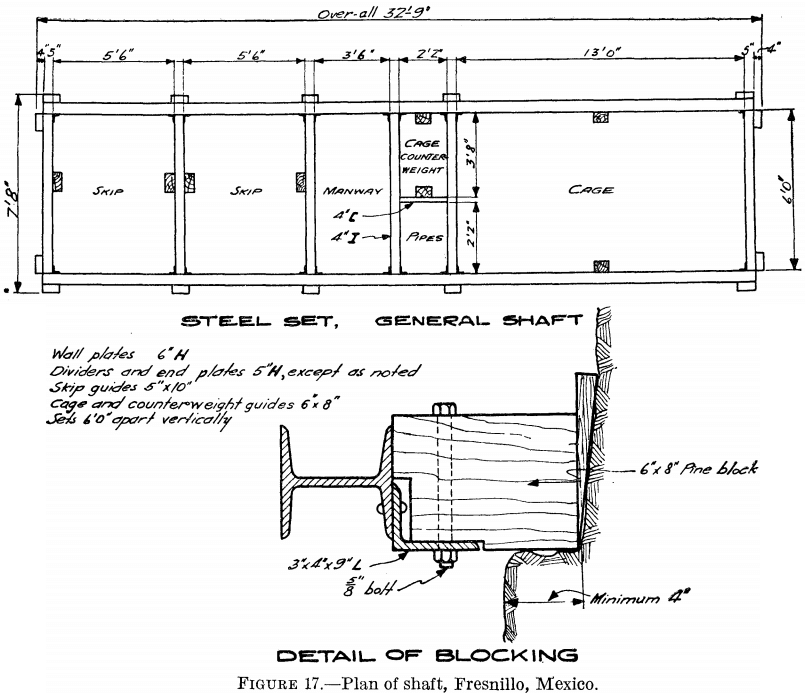
usually economical to make the shaft large enough to accommodate a separate man and service cage, unless the production is so small that a single hoist can handle it easily and perform service duties as well. Where large amounts of mine timber must be handled through the shaft, it may be desirable to provide a separate long cage upon which loaded timber trucks can be run with the timbers lying flat. The long cage is convenient, also, for handling drill-steel trucks with the steel lying flat.
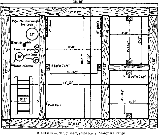
The capacity of a shaft of a given size is usually greater when skips are employed for ore and waste than when cages are used; the net load and the ratio of net load to total load is greater, and less time
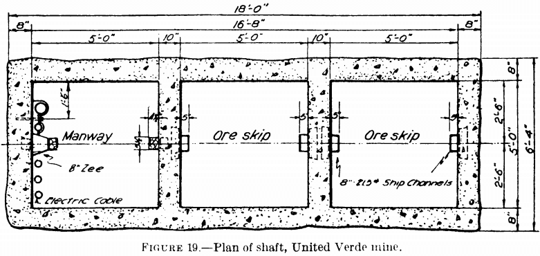
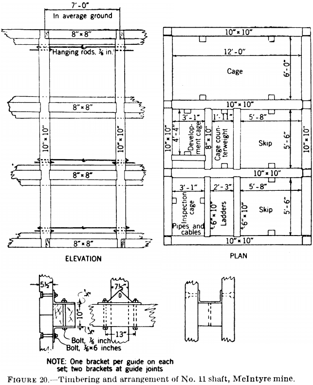
usually is required for loading and dumping. Even when the ore hoist is not used for service work, it is seldom that hoisting can be conducted full time, especially if pockets of considerable capacity are not provided at each hoisting level. The provision of storage pockets of ample capacity, with measuring hoppers for loading the skips, materially promotes maximum utilization of time and shortens the hoisting cycle, hence increases the capacity of the shaft.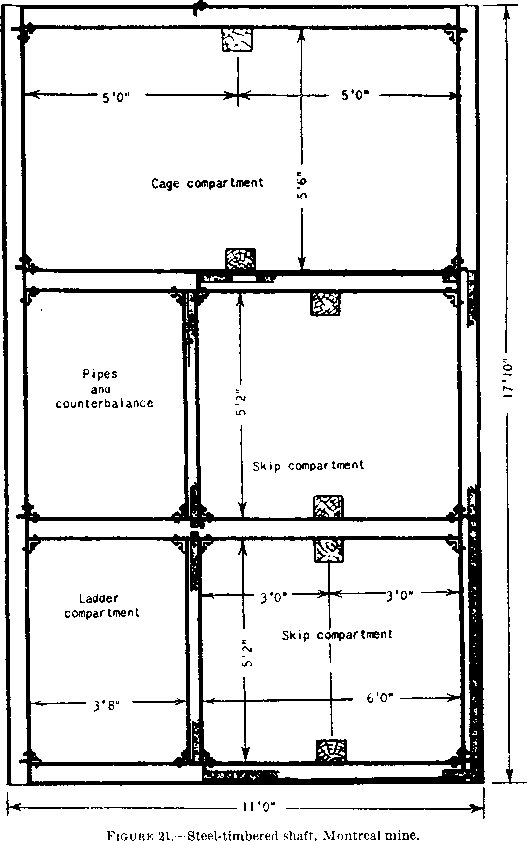
Hoisting in cars on cages has advantages under certain limited conditions, notably in leasing operations where the production from each of a number of sets of leasers must be kept separate from that of the others.
Tables 11 and 12 contain data on typical shafts, their size, number of compartments, daily capacity, and service duties.
