Table of Contents
Column flotation cells, like mechanical cells, are used to perform mineral separations. Column cells do not use mechanical agitation (impellers). Instead, mixing is achieved by the turbulence provided by the rising bubbles. Columns are mostly used to produce final grade concentrates because they are capable of high selectivity. Other features which distinguish them from mechanical cells are their shape, bubble generation system and the use of wash water.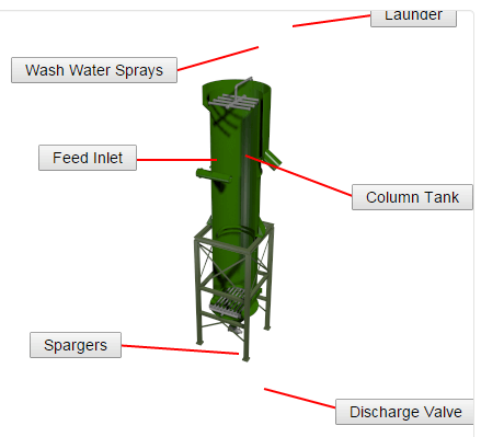
The major components of a column flotation cell are labeled. Select the component to display a description.
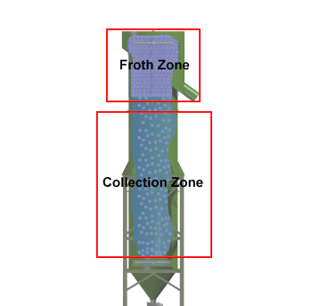
Column cells are considered to have 2 distinct zones; the collection zone and the froth zone.
Because there is no mechanical agitation, column cells have no mixing zone. Instead, particles and bubbles are in contact throughout the collection zone which extends from the spargers to the froth/pulp interface. The feed enters the column near the top of the collection zone and flows down through the rising column of bubbles. Bubble/particle aggregates are formed in the collection zone and are carried up to the froth zone.
Froth Zone
Froth depth in a column is much deeper than in a mechanical cell. This is a result of the columns shape and is similar to the effect of using froth crowders in mechanical cells. Wash water also helps to stabilize the froth by replacing water draining by gravity. This permits a high degree of cleaning, in fact entrainment can virtually be eliminated.
Flotation columns and mechanical cells respond in a similar way to the chemical variables and many of the physical ones. Feed characteristics will have a similar effect on both machines. They also respond to reagents in much the same ways.
Air Rate
Apart from changing grade and recovery, gas rate affects the position of the pulp/froth interface itself. An increase in air rate lowers the position of the interface (increases froth depth). This is similar to what occurs when pouring a glass of pop. The froth is deepest at the start when many bubbles are rising and eventually lowers when less bubbles are being produced, the froth depth is much lower. In some installations, the volume of gas in the collection zone, called air holdup, is monitored. Above a critical air rate (hold up) the column becomes unstable.
https://www.911metallurgist.com/column-cell-carrying-capacity-scale-up
Froth Depth
Froth depths in industrial column installations can range from 50 cm to 2 m. The general effect of changes in froth depth are the same as in mechanical cells. In many cases, however, because of the deeper froth, the effect of changes in depth are often less noticeable with columns.
Wash Water And Positive Bias
An increase in wash water will reduce entrainment thereby increasing grade with a small loss of recovery. For efficient cleaning, the water flowing down should exceed the amount of water carried by the bubbles from the pulp to the froth. This is known as operating the column with a positive bias.
Design Of Column Cells
Column cells are typically 1 – 3 m in diameter and 5 – 15 m high. They can be square, circular or rectangular. They are sometimes baffled vertically into sections to promote better mixing.
Air Spargers
There are 3 main types of spargers: porous, jet, and external in-line mixing.
Porous spargers refer to a class of spargers which are made from material full of small holes. The most common porous materials are fabric, perforated rubber, metal and ceramic.
Jet spargers use a jet of gas, sometimes combined with water, to create small bubbles for flotation. The size and number of bubbles depends on the speed of the jet spray. This in turn is controlled by the size of the spray nozzle hole and by the gas flowrate through the hole.
External in-line mixing spargers consist of a static mixer and a centrifugal pump. The static mixer is a tube containing stationary blades through which slurry and air are pumped. The blades shear the air into very fine bubbles which disperse through the slurry.
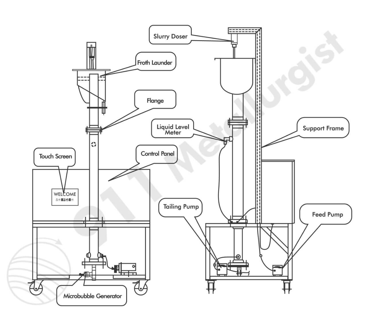
You best contact https://www.metso.com/industries/mining/ for large process equipment.
Advances in Column Flotation
In the 25 years that column flotation has been in existence, numerous advances have been achieved which have facilitated more extensive application of columns in different process stages and for a greater variety of minerals. Most notably, a vast contribution toward understanding flotation phenomena followed by exchange of information from diverse commercial and laboratory experience have led to a knowledge base from which design and operation of columns have become substantially improved.
Specifically the work of Messrs Dobby & Finch at McGill University has become a basis for column design and scale up. The chemical engineering model employed by Dobby & Finch (et al.) describes the flotation process based on attachment kinetics from bubble/particle collision and attachment and relates results from small diameter (plug flow) columns to large diameter columns via dispersion coefficients. By so doing, commercial column results may be accurately predicted from laboratory column testing. From early lab testing experience it became evident that retention time was a primary design criteria. The concensus of more recent data from column operators, both laboratory and commercial, has indicated that superficial feed velocity or column mass feed rate (critical column loading) may be rate determining for column design in many instances. This additional information coupled with information on the effect of particle size on design limitations and approximate reasonable ranges for superficial air velocity, have increased the confidence in commercial column performance from laboratory or pilot-scale testing. The refinement of the column flotation knowledge base has permitted more customized design of columns for specific applications. By use of the concepts of retention time and retention time distribution, superficial feed velocity and critical column loading, laboratory or pilot scale column tests may be conducted to determine the maximum column capacity under optimum conditions. Maximum column capacity may be dramatically different depending on the mineral type, grind size distribution, specific gravity, feed grade, percent solids and selectivity of the flotation chemistry.
Besides the academic contribution, the combined experience of worldwide industrial application has led to improvements in column design. The most notable of these improvements are in sparger design.
Inability of filter cloth or porous rubber bubblers to achieve recoveries equivalent to conventional cells coupled with relatively short bubbler lifespans prompted the U.S. Bureau of Mines to investigate alternative sparger design. Based on these investigations messr’s J.D. McKay and D.G. Foot, Jr. developed the patented “Turbo Air” external bubble generation. Because of its design, this sparger is capable of achieving higher air hold ups and greater bubble size control which have generally resulted in higher mineral recoveries at lower gas flowrates.
Gold Flotation & Columns
In another unique application, hot (120°F) flotation of hot leach tails definitely favored column flotation. Feed for the hot leach process consisted of old plant tailings containing extractable levels of gold. While column and conventional flotation results were again similar, the flotation column required 30 to 50 pct less reagent than conventional flotation. Furthermore, corrections to circuit operation were 3 times more rapid in the column than in the mechanical cell. This resulted in lower losses when flotation problems were encountered. Also, adjustment of column wash water provided fine control of concentrate grade and solids content thus reducing the volume of solids to be processed downstream. After testing, operators preferred column operation to conventional cell operation particularly because of the column’s amenability to computer control. For these reasons, flotation columns have been recommended for this application.
A major Au/Ag plant soon to start up in Nevada will employ two 7 ft diam columns for upgrading of Au/Ag bearing pyrite rougher concentrate from approximately 7 oz/st Ag in the rougher concentrate to 45 oz/st Ag in the column concentrate. Unique aspects of this operation include a low design superficial feed velocity of 0.3 cm/s and a regrind size of 50 percent passing 15 um.
A western U.S. gold producer recently conducted a pilot test in conjunction with the U.S. Bureau of Mines and Control International Inc. personnel to recover residual gold from CIL tailings. Testing was conducted in a 1-ft-diam x 30 ft tall column using the Bureau of Mines external sparger. A bank of conventional cells was operated in parallel with the column. While overall recoveries were marginal for both the column and conventional cell, average concentrate grades were higher for the column. Flotation feed grade was 0.006 to 0.01 oz/st Au with 0.1 to 0.3 oz/st Au column concentrate and 0.05 to 0.20 oz/st Au conventional concentrates. Recoveries ranged from less than 10 to approximately 50 pct. Gold recovery was complicated by: 1) CIL circuit operation, 2) the complex origin of the Au and 3) a complicated reagent scheme.
Laboratory column testing was performed on a Philippines Cu/Au ore to determine column amenability as either a rougher or cleaner stage. Plant feed material contained 1 pct Cu and 0.08 oz Au/st. Mechanical rougher concentrate contained approximately 12 pct Cu and 0.8 oz Au/st. Typical mechanical cell plant overall recoveries were 87 pct for Cu and 77 pct for Au with final concentrate grades of approximately 26 pct Cu.
Rougher column flotation succeeded in producing concentrates of 21 to 24 pct Cu and 1.5 oz Au/st with an average recovery for Cu of 90.3 pct and 91.6 pct for Au.
Typical plant cleaner recoveries were 95 to 98 pct for Cu and Au. Cleaner column flotation succeeded in producing final concentrate grades of 28 to 29 pct Cu and 1.37 oz Au/st with recoveries of 96.1 pct for Cu and 96.3 pct for Au.
Effect of Aeration Rate
Flotation columns are generally operated at a maximum aeration rate for any given set of conditions in order to maximize flotation recovery and throughput. Figure 6 shows the results of simulations in which the air flow rate has been increased while all the other

factors were kept constant. For low feed rates, the improved recovery can be directly related to an increase in the flotation rate constant given by Equation [3]. As before, the higher recoveries result in the collection of additional middlings particles which tend to increase the product ash content.
At high feed rates, the column becomes carrying-capacity-limited. According to Equation [11], the product flow rate should be directly proportional to the aeration rate. This type of behavior is observed in Figure 6 for a superficial feed rate of 0.40 cm/s. At intermediate feed rates, both the flotation rate constant and the carrying capacity play a role in determining column performance. As the gas rate is reduced, the available surface area passing through the froth phase for bubble-particle attachment is reduced. Thus, the column becomes carrying-capacity-limited at a lower feed rate when the gas rate is low.
As discussed previously, an improvement in product grade occurs when the column becomes carrying-capacity-limited. For both the intermediate and high feed rate situations, a decrease in gas rate increases the circulating load between the pulp and froth. This, in turn, produces an incremental improvement in product quality which lowers the product ash content.
Effect of Pulp Bubble Size
A number of studies have been carried out during the past several years which suggest that column performance can be improved by decreasing the size of bubbles in the flotation pulp. In order to examine this possibility more closely, a series of simulations have been performed as a function of pulp bubble diameter.
Figure 7 demonstrates the effect of changing pulp bubble size on recovery and product ash content. As the bubble size is decreased, the flotation rate constant increases in accordance with Equations [3] and [5]. This results in a slight increase in recovery which is somewhat offset by a corresponding increase in air hold-up that reduces the effective retention time of particles within the column (Equation [7]). Since the simulations were conducted while
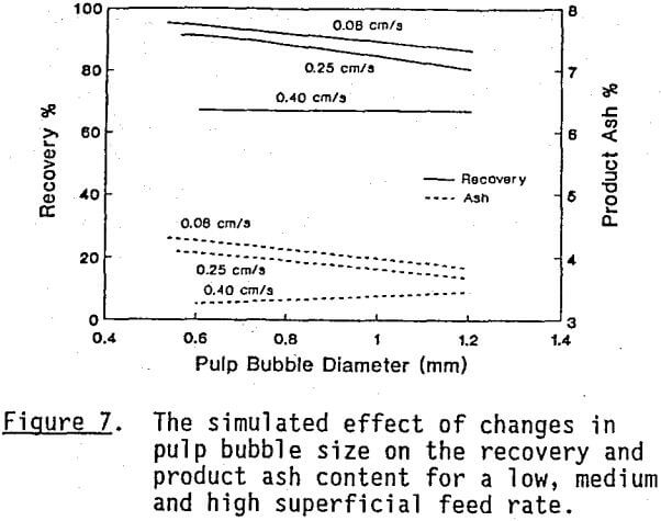
holding all other parameters constant, the pulp bubble size had no influence on recovery under carrying capacity limitations.
In terms of product quality, a decrease in bubble size produces a corresponding increase in product ash content as the operating point moves along the characteristic recovery-grade curve. However, under carrying capacity limitations, the product quality improves as the bubble size is decreased. This improvement is probably due to an increase in the pulp-froth circulating load which becomes more pronounced as the rate constant is increased through the use of smaller bubbles.
Effect of Column Height
One of the key design variables in column flotation is the height of the collection zone. The results of simulations conducted as a function of column height are shown in Figure 8.
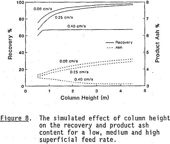
The simulation data indicate that the influence of column height on column behavior is similar to that of varying the particle hydrophobicity (i.e., Pa). For low and intermediate feed rates, the retention time of particles increases as the column height is increased (Equations [7] – [9]). As a result, the longer retention time produces a higher recovery. However, once the column becomes carrying-capacity-limited, an increase in column height provides no additional improvement in recovery.
For the low and intermediate feed rates, product ash content increases with recovery as more middlings particles report to the product stream. At higher feed rates, the column once again becomes carrying-capacity-limited. As a result, each incremental increase in column height increases the circulating load between the pulp and froth. The net effect is to concentrate the fast-floating particles and improve the product quality.
Effect of Feed Solids Content
The effect of feed solids content on recovery and product ash is shown in Figure 9. In general, the simulation results indicate no change in the recovery of coal or ash rejection when the feed rate to the column is relatively low. However, as the feed rates are increased, the column begins to become very sensitive to the pulp density of the feed. This is due to the fact that the column becomes carrying-capacity-limited at a much faster rate. There is simply an insufficient amount of bubble surface area to carry the additional particles out of the cell.

As expected, the feed solids content has no influence on product grade unless the column becomes carrying-capacity-limited. It should also be noted that the effect of feed solids content on other flotation variables, such as reagent concentrations, have not been considered in the simulator. However, experimental evidence suggests that this phenomenon can have a significance influence on column performance in some cases.
Effect of Froth Bubble Diameter
The simulation results shown in Figure 10 demonstrate the effect of froth bubble size on column performance. As froth bubble size increases, there is a net loss of available surface area on the bubbles for attached particles. This produces a corresponding reduction in the number of particles recovered in the froth product. As expected, this effect becomes more pronounced as the feed rate to the cell is increased. The product ash content also improves under carrying capacity limitations, which can be explained by the increased circulating load between pulp and froth.

It is also worthwhile to mention that preliminary laboratory data at Virginia Tech indicate that the pulp and froth bubble sizes may be related. In general, a smaller bubble size in the pulp corresponds to a smaller bubble size in the froth. As a result, changes in the pulp bubble size may have a more drastic influence on column performance than initially indicated in the foregoing section.