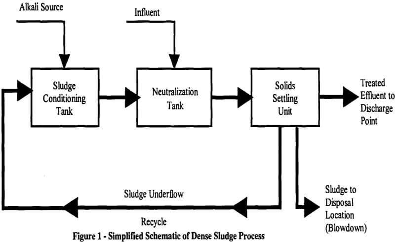
Figure 1 presents a simplified process flow diagram of the Dense Sludge process. The most significant change between Dense Sludge technology and conventional metals treatment is the method by which the alkali source is added. In conventional treatment systems, the alkali is added directly into the influent to achieve a desired pH setpoint. Generally, that setpoint is the pH at which the minimum solubility occurs for the target metal(s), or at the pH where discharge limitations can be reliably met. In the Dense Sludge process, the alkali source is combined with recycled sludge before being combined with the influent. The alkali source can be lime, caustic, ammonia, or any other neutralization agent which reacts readily and can be continuously metered.

The sludge particles react with the alkali to provide attraction sites for the removal of metals and cause the gypsum crystals to grow. The continued recirculation of sludge ultimately converts the metal hydroxides to oxides through a series of steps.
The method of feeding the alkali (proportioning valve, proportioning weir box, or metering pump) is the same for both conventional and dense sludge systems. In some cases we have found that the pH setpoint can be lowered with the Dense Sludge system and still maintain optimum metals precipitation. The sludge for recirculation is withdrawn from the solids settling unit and pumped to the sludge conditioning tank where it combines with the alkali source. The resultant mixture of sludge and alkali is then directed to the neutralization tank where it combines with the influent. The demand for alkali depends upon the system pH setpoints and a probe in the Neutralization Tank provides continuous measurement and feedback to the proportioning device. Many operators of treatment plants which have been converted to the Dense Sludge process report a savings in alkali consumption.

The sludge generated in the solids settling unit is recirculated constantly at a rate sufficient to meet the constraints of the dense sludge process. In addition to continuous recycle, a certain quantity of sludge is removed from the system each day to maintain the equilibrium of the system. For best results this blowdown stream should be designed to handle the maximum anticipated loadings on a continuous basis and then it can be operated intermittently to maintain the density of the recirculated sludge or to keep this density within a target range, say 15 to 25% solids. For acid mine drainage derived from coal mining sites, we have found that 20% solids or less provides a good working density with lime alkali and ultra high molecular weight (UHMW) cationic polymer used as a settling aid.
For applications involving other metals, 20 to 30% solids in the underflow from a clarifier/thickener is achievable. There are, of course, exceptions to these situations. One facility, which has high iron and sulfate loadings, uses no polymer and achieves underflow solids in the 35% range with lime.
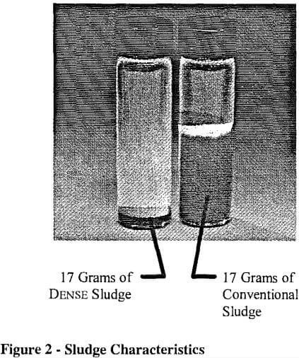
Because the chemicals used and unit operations all remain the same with the Dense Sludge process, implementation of the process typically requires only the installation of small tanks, mixers, pumps, piping, flow meters, and valves. No new major equipment is required. Using the Dense Sludge process to eliminate the interstitial water in sludge particles, the solids in the sludge are denser and will settle more rapidly. This improvement in the characteristics of the sludge directly correlates to increased percent solids achieved in the sludge blanket in the thickener/clarifier and a decrease in the quantity of waste sludge generated. The percent solids ranges discussed previously compare to a typical range of 1 – 3% solids with conventional systems. The difference in the sludge characteristics is illustrated by Figure 2.

