The maximum settlement (S) of the soil subbase occurs at the center of the wetted soil column. There would be little to no settlement along the dry edges of the column. The total settlement can be estimated by multiplying the percent soluble minerals times the controlling depth, DI. As the liner deflects to fill the void created by the settlement, it pivots along the outer edge of the wetted soil column. In cross- section, the deflected liner would appear to be a “V” shape.
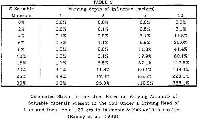
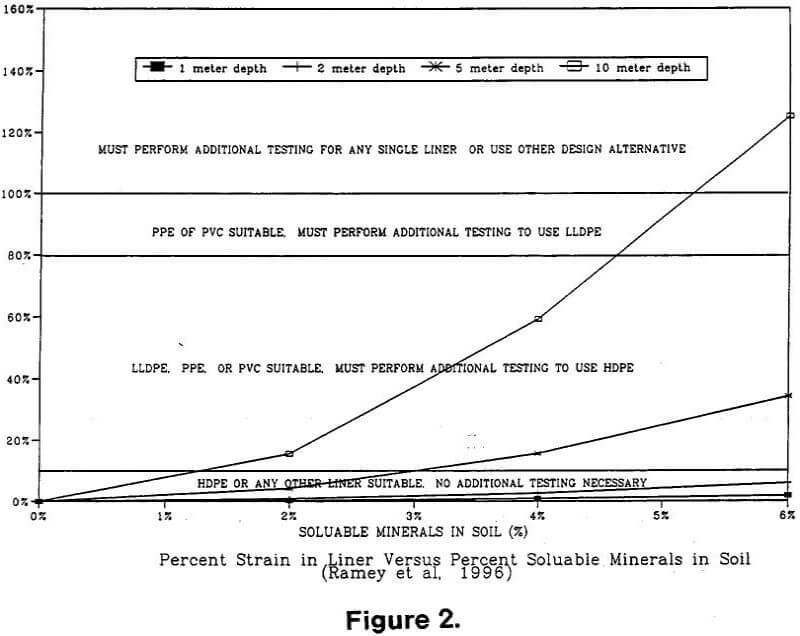
The liner elongates to fill the void. This elongation is known as the strain. The percent strain can be calculated by the rules of a simple right triangle. The strain is calculated by subtracting the original radius of the wetted column from the hypotenuse and dividing that value by the original radius. The value obtained is then multiplied by a factor of safety (FS) to obtain the design strain. For preliminary design, a minimum FS of 5 should be used for the selection of the geomembrane liner. Table 3 provides a summary of calculated strains in the liner versus the percent soluble minerals for a K = 3 x 10 -5 cm/sec. A graph of the values for soluble mineral contents of up to 6% are provided in Figure 2.


Various testing firms and manufacturers report that HDPE can resist multi-axial strains between 10% and 35%. Given a FS of 5 for preliminary design, the predicted strain εp should not exceed 2% for the lower bound of HDPE. A minimum design strain εd of 80% is typically used for LLDPE and values for PVC and PPE are normally 100%. Therefore, εp should not exceed 16% and 20% for the LLDPE and PVC/PPE materials, respectively. Horizonal lines have been drawn across the strain graph (Figure 2) to show the upper limits of ed for the various material types given the soil and solution head conditions shown.
The steps involved to estimate the settlement and strain in the liner, given the presence of soluble minerals within the subbase of a heap leach pad liner are outlined below. With this information, he can determine the geomembrane liner type that may best suit the proposed heap leach pad construction.
Step 1 – Determine acid consumption (AC), AC = (NP/(Normality of solution 25)) [Ref.7]
Step 2 – Determine amount of solution loss (Vw) through hole in liner using Table 2 [Ref.2] and leach cycle information.
Step 3 – Determine the weight (W) of soil in one linear meter of the soil column using density of soil and the wetted radius (r) found in Table 1 [Ref.2].
Step 4 – Determine the depth of influence (DI) as controlled by AC, DIAC = (Vw/AC)/W
Step 5 – Determine the retained moisture (Mr) of the soil within the column on a per linear meter basis using field moisture and laboratory field capacity values.
Step 6 – Determine DI as controlled by Mr, DIMr = Vw/Mr
Step 7 – Compare calculated DIAC and DIMr with depth of zone of soluble salts (DIS), lesser of the three value controls.
Step 8 – Determine total differential settlement (S), S = (loss of mass (%)/100) DI
Step 9 – Calculate predicted strain in liner (εp), εp = ((((S²+r²)0.5)-r)/r) 100, or use Table 3 for DI<10 m
Step 10 – Calculate design strain εd, εd = εp FS, FS = factor of safety = 5 for preliminary studies
Step 11 – Compare design strain with multi-axial elongation values (see horizontal lines) for liner materials in Figure 2 and select liner material.

