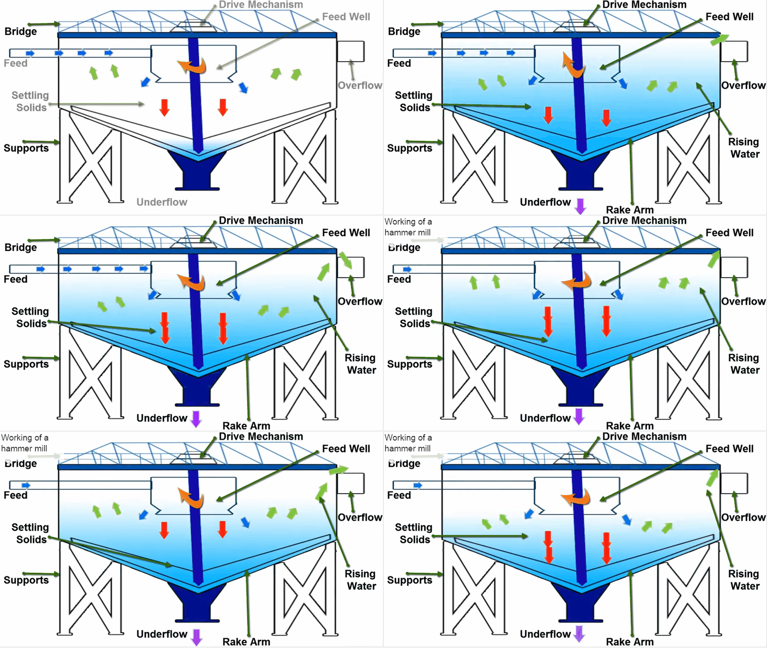
 Under normal conditions our EXAMPLE mill feed thickener rake drive will operate with the gear mechanism lowered, regardless of grinding or leaching operations. Operating lights on the mill control panel indicate whether the rakes are fully lifted, fully lowered, moving up or down, turning or stopped. An exact intermediate rake position is not indicated on the panel; however, close scrutiny of the panel lights will give an indication of the rake position.
Start up of the thickener must be performed locally. Prior to starting the thickener, the rakes must be raised. Once the rake drive is started, the rakes can be lowered with the gear mechanism. Should the rake drive be started after lowering, or the process material be too dense, an impending high torque situation will alarm at the mill control panel annunciator at 40% torque. The rakes can then be lifted from either the control panel or locally. If the rakes are not lifted or the 40% torque situation alleviated, the rake mechanism will raise the rake gear mechanism and stop the rake drive automatically on an 80% high torque situation. Both impending and high torque alarms are annunciated at the mill control panel.

The thickener underflow lines are buried below the tank, and are encased in larger pipes to facilitate removal should the lines sand up. In addition, purge lines are provided which enter the underflow line close to the thickener discharge cone. The thickened slurry is drawn from the thickener with one of two 7.5 HP 2.5″ variable speed centrifugal pumps. A selector switch at the MCC will select between the pumps. Gland seal water to each pump must also be shut off or turned on manually at the time of a pump switch over. The speed of the pump is controlled by a density controller. A nuclear density source, detector, and transmitter measure the density of the thickener underflow and send a 4-20mA signal to the controller, proportional to the increasing density of the process material flowing through the pipe. The controller adjusts the pump speed by sending a corresponding 4-20mA signal to the variable speed drive in the MCC; the higher the density of the slurry, the higher the controller’s output signal to the drive. The greater the density of the slurry, the faster the flow rate out of the thickener tank. The setpoint of the density controller is set at 60% solids. The density of the thickener underflow is recorded on a recorder which also records the cyclone feed density.
Thickener underflow is fed through a 48″ diameter trash screen and sampler to the Leaching Circuit. The trash screen, with its vibrating mechanism, removes any large pieces of trash (wood, plastic, metal, etc.) in the slurry to a pail or box, which must then be manually disposed of. The thickener underflow slurry must be diluted prior to leaching, and therefore barren solution at a rate of 12.8 cubic meters per hour is added to the trash screen, diluting the slurry from a 60% to a 45% solids slurry. The slurry passes through the trash screen into a recycle box which provides a means of directing flow back to the thickener feed well, or to the second leach tank, bypassing the first leach tank. The leach feed sampler, located in the recycle box, is of a grab sample type run by a timer.
https://www.911metallurgist.com/ball-mill-operation-starting-grinding-circuit-shutdown-procedure
https://www.911metallurgist.com/thickener-startup-shutdown-procedure
