EXAMPLE Tailings System
Tailings from the processing plant are collected in a common tails box and flow by gravity to the tailings pond. The tailings flow at a rate of 51.6 cubic meters per hour and 34% solids. The tailings line consists of five separate sections and each individual section is designed to suit its local topography. Leak detection is provided by two magnetic flow meters and/or by a sluice gate into the tailings pond. This section is intended to be read in conjunction with Flowsheets and Piping and Instrument Diagram.

Detailed Process Description and Control
The major portion of tailings from the processing plant are from the rougher flotation cells. The tailings flow at a rate of 49.6 cubic meters per hour and 35% solids and are combined with 1.5 cubic meters per hour of barren solution prior to flowing into the tails box. The tailings system must be operated close to the design throughput of 20.8 tonnes per hour solids, and the tailings solids content must be in the range 30-40% by weight.
A primary tailings sampler located in the top of the tails box takes regular samples of the mill’s tailings. The primary sampler passes its sample through a secondary tailings sampler and into the 2 HP 2″ vertical tailings sampling pump. Tailings from the Argentite Leach Circuit flow through a sampler and discharge into the same tailings sampling pump. The contents collected in the tailings sampling pump are pumped into the tails box.
The tails box is equipped with a high level switch and high level alarm which will alarm at the mill control panel annunciator on a high level condition. A reclaim water line is also provided at the tails box to dilute the tailings should the tailings become too dense to flow freely. A hydrogen cyanide detector and alarm is located in the general vicinity of the tails box and will alarm at the mill control panel annunciator a high hydrogen cyanide gas condition.
Tailings discharge from the tails box through one of two tailings lines. Each discharge line is equipped with a knife gate valve to isolate one line from the other. Only one valve should be open at any time.
Although there are two discharge lines from the tails box only one line should be used while the other is held on standby. The line equipped with the magnetic flowmeter should, under normal operating conditions, be the line used. If the standby line is to be used for an extended period of time, the magnetic flowmeter can be removed and installed in the standby line.
The tailings line is equipped with two magnetic flowmeters located at the tails box and tailings dam, respectively, which measure the tailings flowrate at either end of the tailings line. A differential flow alarm compares the signal from the two magnetic flowmeters and alarms the mill control panel annunciator if the flowrate measured at one flowmeter is different from that measured at the other flowmeter. This differential flow alarm will detect a leak in the tailings line.
The tailings line as a whole is divided into five sections as follows:
Section 1 – The buried pipe in the plant site area is 6 inch pipe flowing partially full. Under the building foundation, there are two parallel pipes, because of the lack of easy access for maintenance. Only one pipe should be used at a time.
Section 2 – The pipe along the upper road is 4 inch series 60 pipe, flowing partially full at the upstream end, and full at the downstream end. There are two stand pipes in this section to allow air to enter or exit the pipe. These stand pipes must always be open.
Section 3 – The pipe along the steep section by the road switchbacks is 4 inch series 200 pipe flowing partially full. The very high velocities in this section cause abrasion of the pipe wall, which should be checked often. The most severe abrasion occurs at the bottom of the slope where the pipe turns 90 degrees. This corner is made of rubber-lined steel pipe for maximum abrasion resistance. Three replacement elbows are provided.
Section 4 – The pipe from the steep slope to the edge of the dam is 4 inch series 100 pipe, flowing full most of the way. The downstream end of the pipe is under pressure to ensure flow along the flat dam top.
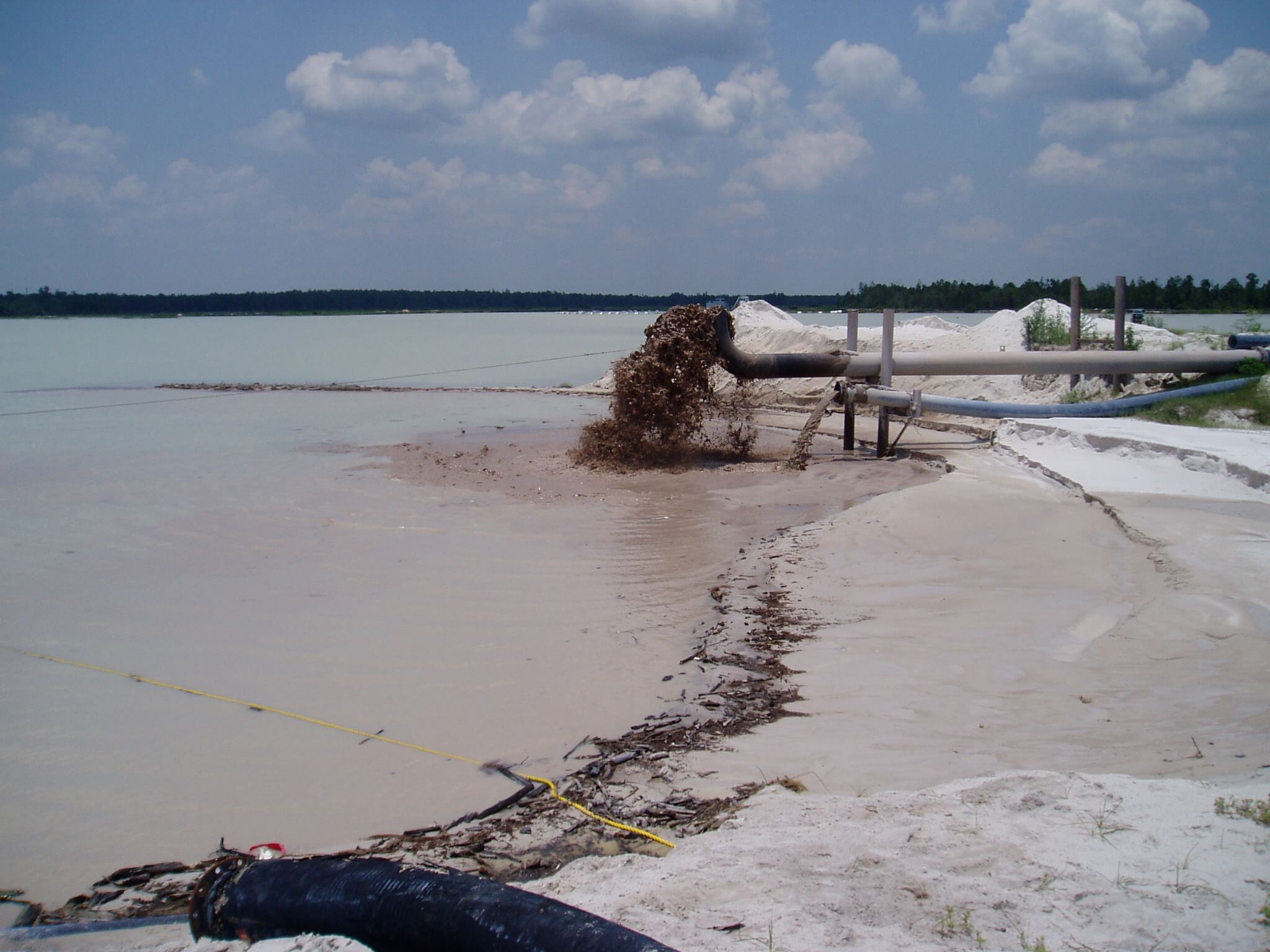
Section 5 – The header pipe along the top of the dam is 4 inch series 100 pipe flowing full. Tailings are discharged through six 4 inch spigots, which can be closed with pinch valves. Only one spigot at a time must be open, because the velocity of the tailings downstream would be so low as to cause settlement of the solids if more than one were open. Therefore, the pinch valve on the header pipe immediately downstream of the operating spigot must be closed, after opening the spigot.
NOTE THAT TAILINGS MUST BE DISCHARGING FROM A SPIGOT AT ALL TIMES, OTHERWISE THE FLOW WILL RAPIDLY BACK UP, AND THE TAILINGS PIPE WILL BURST DUE TO EXCESS STATIC PRESSURE.
Spigots downstream from the operating spigot must be left open to facilitate drainage of the line. As the line is laid flat, some deposition will occur. However, the deposited solids should be flushed out when flow is re-admitted to that section of the header.
During winter operation it is anticipated that the deposited solids will freeze, partially blocking the pipe. Therefore, begin discharge at spigot No. 6 in November, and proceed backwards to spigot No. 1 in April, using a new spigot every month. From May to October, reverse the cycle.
https://www.911metallurgist.com/plant-tailings-reclaim-process-water-system-startup-shutdown-procedure
