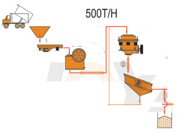
This EXAMPLE Small Crushing Plant is designed to crush 500 tonnes per day, operating 12 hours per day with an availability of 70%. The Plant will crush run-of-mine material (-16″) to 100%, passing 5/8″ at a rate of 60 tonnes per hour. Start-stop stations are provided for all equipment in this Plant at the crusher control panel, to facilitate remote control. A jog/stop station is provided locally for maintenance and checking as well as equipment shutdown. This guide is intended to be read in conjunction with the Flowsheet, Piping and Instrument Diagram.
The Crushing Circuit is designed to the following criteria:
| Run-of-mine Ore Size | 16″ |
| Ore Bulk Density | 1.6 tonne/meter3 |
| Ore Moisture Content | 3% by weight |
| Jaw Crusher (Closed side setting) | 3″ |
| Cone Crusher (Closed side setting) | 1/2″ |
Detailed Process Description and Control of our EXAMPLE small crushing plant
 Run-of-mine ore is delivered to the Crushing Plant via mine rail cars or underground mine haulage trucks, and is dumped through a 16″xl6″ grizzly into a 350 tonnes coarse ore bin. Oversize material on the coarse ore bin grizzly must be manually removed and broken. The broken material can then be fed into the coarse ore bin. The underside of the coarse ore bin opens onto a 42” variable speed apron feeder, on which there must be a continuous pile of ore to prevent fresh ore from falling directly onto the apron feeder. A nuclear level switch is mounted at the coarse ore bin discharge chute to alarm at the crusher control panel and shutdown the apron feeder should the level drop below a predetermined point. The speed of this feeder is controlled by a hand dial located on the door of this drive in the MCC. Once a speed has been set, and conforms to the feed rate of subsequent equipment and incoming material, the speed can be left constant.
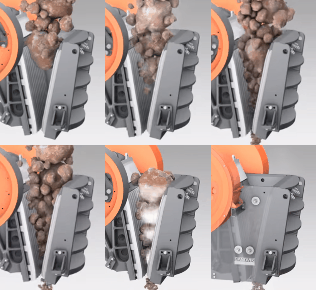
 Ore from the apron feeder flows over a 3″ stationary grizzly, the +3″ ore being fed to a 100 HP 24”x36″ jaw crusher, and the -3” allowed to flow directly to a 24” conveyor. An interlock is provided whereby the apron feeder will stop if the jaw crusher stops, or if the first conveyor stops. This first conveyor (#1) also has other interlocks, as will be described in the following paragraph.
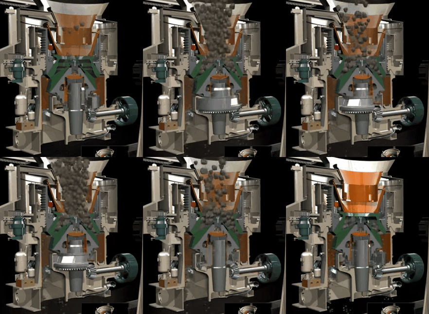
Secondary crushed material from a 150 HP 4′ standard cone crusher is also discharged onto conveyor #1. An electronic soft start unit in the crusher MCC section for this drive ramps the voltage to the motor on a start. A warning horn will sound when the conveyor #1 start button pushed and the conveyor will start 30 seconds later. A speed switch is located at the tail pulley of conveyor #1. Six pullcord switches, two located at each pulley and two in the centre of the conveyor, immediately shut the drive down should one be pulled in emergency. A plugged chute detector (tilt switch) will stop the motor should the material build up at the discharge. A tramp iron magnet, suspended above the discharge of conveyor #1, is designed to pick up drill steel and other tramp iron, in order to prevent this material from entering the cone crusher. The magnet is locally controlled only, but will alarm at the crusher control panel should its power fail. The magnet is to be swung away from the conveyor prior to shutting it off to prevent the tramp metal from falling back onto the conveyor.
Conveyor #1 discharges onto a second 24″ conveyor (#2), which has the speed, plugged chute, and pullcord switches as described for conveyor #1, except that this conveyor has only 4 pullcord switches. In addition to these switches, a metal detector is positioned above the belt to stop the motor and alarm at the crusher control panel upon metal detection. The size of metal pieces to initiate the alarm is adjustable on the detector.
Conveyor #2 discharges onto a 6′ X 10′ double deck vibrating screen. Oversize material from both screen decks is fed to the cone crusher and recycled back to conveyor #1. Undersize material from the bottom screen, -5/8″, is discharged onto a 3rd conveyor, the 24″ #3, and conveyed to the 500 tonne live capacity fine ore bin. If either conveyor #3 or the cone crusher shut down, the screen will stop. On shutdown of the screen; subsequent interlocks shut down the plant.
 The cone crusher is equipped with its own lubrication system, including two lube pumps one of which must be running prior to the cone crusher drive start. The cone crusher drive will stop if the both lube pumps are stopped. A low pressure switch in the oil feed line will stop the lube pumps on a low oil pressure condition and hence stop the cone crusher after a 1 minute delay. An oil temperature switch and alarm in the oil return line will alarm on a excessively high oil temperature. On shutdown of conveyor #1, the screen will stop; however, the cone crusher will continue to run. A conditional interlock is provided to allow the screen to start without conveyor #1 running, provided the apron feeder and the jaw crusher are stopped. This conditional interlock is to allow for a general start-up of the Crushing Circuit.
A flowsheet would graphically illustrate the interlocks between all the equipment in the Crushing Circuit. Conveyor #3 is similar to conveyor #2 with respect to speed, pull-cord, and plugged chute switches. On a high fine ore bin level the apron feeder is shut down immediately, and after 5-10 minutes (software adjustable) conveyor #3 shuts down, followed by the entire Crushing Circuit, through the respective equipment interlocks. This time lapse should allow for material to empty from all the equipment in the Crushing Plant.
The Crushing Plant is equipped with a 12000 CFM wet dust scrubber and a 10 HP scrubber bottoms pump which run together in automatic mode, and will shut conveyor #3 down after a delay of 5 minutes if this system is stopped (subsequent interlocks will shut down the entire circuit except for the jaw and cone crushers) . Pick up points for the dust collection system are: discharge of the apron feeder, grizzly discharge chute at conveyor #1, jaw crusher discharge chute at conveyor #1, cone crusher discharge chute at conveyor #1, transfer point between conveyors #1 and #2, screen feed chute, cone crusher feed chute, and the screen undersize discharge chute at conveyor #3. The collector empties its contents in to the 10 HP 2″ vertical scrubber bottoms pump, where reclaim water is added. Level is maintained in the pumpbox by a float and link control valve. A portion of the pump discharge recirculates back to the dust collector, the remainder is pumped to the cyclone feed pumpbox.
The Crushing Plant is also equipped with a 5 tonne overhead crane and a 15 HP 2″ vertical sump pump and sump. The sump pump operates automatically on a high/low float level control, or manually. The sump pump also discharges to the cyclone feed pump-box or to the grinding area sump. Should a fire occur in the crushing plant, for safety, a flow switch in the fire water pipe will stop conveyor #3, hence the entire Crushing Plant.
https://www.911metallurgist.com/crushing-plant-start-up-sequence-procedure
