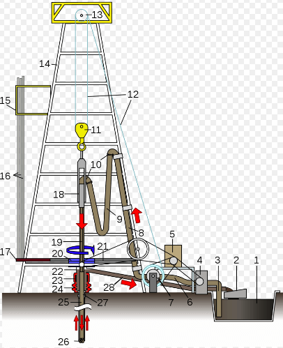
During the past few years the taking of cores in drilling with rotary equipment has been perfected to a remarkable degree in the Gulf Coast fields of Texas and Louisiana. Taking of cores is becoming quite a common thing, especially in the newer fields, and drillers are becoming expert in this work. The writer has seen cores 5 to 8 ft. long taken with great ease in wells as deep as 4500 ft. Coring is doing much to remove the prejudice which so many petroleum engineers seem to have against the use of rotary drilling equipment for exploratory work. Some operators are now claiming that when used with a reasonable amount of coring the rotary system is even more satisfactory than cable tools for exploring in certain territory. A case has recently been pointed out in the South Electra field of North Texas, where producing oil sands, passed over by cable-tool drillers, are being brought in with rotary equipment.
It seems that in this particular territory the sands are rather thin. Cable-tool drilling was carried on for the most part in a wet hole and the red mud encountered in drilling caved into the hole very badly, so that the cuttings showed mostly red mud and the driller, thinking that the sand did not amount to anything, carried his water string through the sand. The later operators, drilling into the sand with rotary equipment and coring it, found that it was well worth testing.
Wells producing from 50 to 500 bbl. per day have resulted. The tables seem to be turning, in the old arguments against the rotary.
Coring can be carried on just as quickly and with a, great deal more safety with rotary drilling equipment than with regular core-drilling machines when drilling in the soft and unconsolidated formations of the Gulf Coastal plain. The writer is very doubtful as to the possibilities of adapting regular core-drilling machines to Gulf Coast conditions.
In working on the problem of taking cores when drilling by the rotary system in this territory, some very ingenious devices have been perfected. These group themselves naturally into the non-reaming and reaming types.
The basket, or toothed, barrel, a non-reaming type barrel, is made from an ordinary piece of drill pipe by cutting teeth in one end. The teeth should be so cut that when they are bent together in effecting closure there will be no wide apertures through which soft sands can escape. The number of teeth depends on the size of the barrel and the type of formation to be cored. The most common size of barrel is the 4-in., but for deep work the 3-in. barrel is often used. The 4-in. barrel will have five or six sharp teeth for coring in soft sands or four flat teeth for coring in hard formations. Some drillers, when coring anhydrite or limestone, use only a single notch cut in the barrel. The barrels with the teeth are usually annealed before running and are usually 3 to 5 ft. long.
USE OF BASKET-TYPE BARREL
The common procedure in running this type of barrel in soft formations is to lower it on the drill stem into the hole until the bottom of the barrel is about 2 ft. off bottom. The swivel is then connected and the mud pump is operated for a few minutes until all material that may have entered the drill stem during its descent is pumped out. With the pump still working, the drill stem is lowered to within a few inches of the bottom. The pump is stopped and the core barrel is rotated downward until 3 or 4 ft. of core have been taken. While lowering the drill stem, the driller is careful not to put too much weight on the barrel; when a sufficient amount of core has been taken, he allows the full weight of the stem to rest on the barrel, while rotating, in order to effect closure. He may raise the stem and drop it a few inches to assist in the closing of the bottom of the barrel. If coring in rock, the driller may unscrew the swivel and drop in some pieces of gravel, glass, or cast iron, and pump them down around the core. By raising the stem and lowering it these pieces get jammed around the core and hold it until it is removed from the hole.
ADVANTAGES AND DISADVANTAGES
This type of core barrel is simply screwed on to the end of the drill stem, no back pressure valve being used. A 5/8-in. hole, called a “weep” hole, is usually bored in the top of the barrel, which permits the drill mud to escape from the stem as it is removed from the hole. The Hughes Tool Co. of Houston is making a special collar to be used in connecting the core barrel to the drill stem. This collar is about 18 in. long and is made from a drop forging with a ground seat ¾ in. in diameter in the center of the collar. The ground seat is at the top of the opening through the collar. About 3 in. above this ground seat, there is a 5/8-in. weep hole opening to the outside of the collar. Coring proceeds as described above, when using this tool, until the driller is ready to pull out. At this point the driller drops a steel ball 2 in. in diameter into the drill stem, which becomes lodged on the ground seat and acts to keep the drill mud from washing through the core barrel and washing out the core as the drill stem is being removed from the hole.
Hundreds of operators are using the basket-type core barrel in Texas and Louisiana. It has the advantage of being relatively inexpensive and easy to make. The following objectionable features have been pointed out in connection with its use:
Hole not Reamed to Gage.—After taking a core with this device it is necessary to ream the hole to gage. This takes almost double drilling time and hence adds to the cost of drilling. It has the advantage of allowing the driller to “rat hole” ahead and if the sand cored carries values he may be able to land pipe on top of the sand. This advantage is somewhat problematical, however, as it is extremely doubtful that an operator could land pipe as close to a sand as would be necessary with a coring device taking such short cores.
Chemical Constituents of Sand Leached Out.—Due to the fact that the drill mud, which ordinarily contains fresh water, comes in intimate contact with the core, any saline constituents may be leached out before the core is removed from the hole. This is a very serious objection as the operators always want to know whether or not the sand cored contains salt water.
Core Apt to be Injured by Heat.—Several writers have recently pointed out the fact that cores are sometimes badly burned or fused from the heat generated while effecting closure. In many cases this heat is sufficient to weld the cutting teeth together and shale cores have been melted into a slag resembling volcanic rock. Of course this completely destroys all of the original characteristics of the core arid it is decidedly not to be desired. Cases of burnt cores are relatively rare in proportion to the number of cores taken.
Cores Lost Due to Failure of Core Barrel to Close.—This condition arises in the coring of soft sands where complete closure is not effected. Also, in the taking of rock cores, it sometimes happens that they do not catch the core. Accidents of this kind are expensive due to time lost and failure to get accurate sample.
AUGER-TYPE CORE BARREL
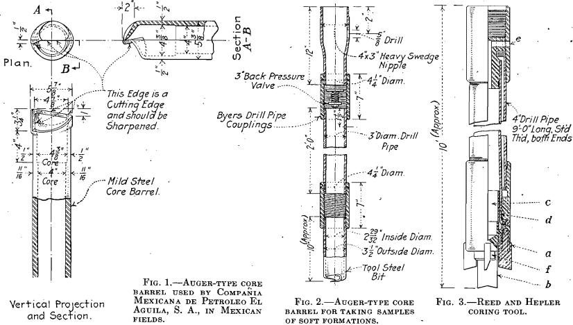
The auger-type barrel, non-reaming, shown in Figs. 1 and 2, is not really a coring device, as the formation is considerably cut up in getting it into the barrel. Probably it would be more correct to call it a sampling device, but because it is used for the same purpose as the ordinary core barrel it is included in this discussion. This tool has a cutting action somewhat similar to that of an ordinary auger; it is made by cutting and bending a lip over the bottom of a piece of pipe.
These barrels usually are run without pump circulation, and in that case no back-pressure valve is used. If the pump circulation is used while coring, it is necessary to use the back-pressure valve, as shown in Fig. 2. This type of barrel does not have to be closed when pulled out; the lip is relied on to hold the sample in the barrel; samples of very loose sands are sometimes lost. Because the barrel is not closed, there is no heat generated ; hence this method does possess some advantage over the basket-type barrel. Except for this one point, the auger-type barrel has all of the objectionable features of the basket-type barrel.
The Reed and Hepler coring tool (sometimes referred to as the R & H tool) is a reaming type of core barrel that has only recently appeared in the Gulf Coast fields. It is manufactured by the Reed Roller Bit Co. of Houston, Tex., and is shown in detail in Fig. 3. This tool seems to possess more of the desirable features of a coring device than any other which has come to the attention of the author. It possesses the following advantages:


ADVANTAGES OF REED AND HEPLER CORING TOOL
Hole Carried to Full Gage During Coring Operations.—This is accomplished by the use of inserted cutting teeth a as shown in Fig. 3. Mud is circulated constantly during the operation of this tool and the teeth cut an annular portion of the hole, the cuttings from which are returned to the surface in the drill mud.
Barrel Kept Clean Until Coring Starts.—This is accomplished by the small plug bit b which is screwed in place in the bottom of the barrel from the inside of the barrel on assembly. When the core tool is placed on bottom the blade of the plug bit is engaged in the formation. When rotation begins it remains stationary and the core tool unscrews down over it. As the coring proceeds the released plug bit and guide c ride up into the core barrel on top of the core.
Core Not Leached of Saline Content While in the Barrel.—On account of the barrel being kept closed and the method of cutting core, it is claimed that the sand core when removed from this type of coring device will come very close to having its original saline content.
Length of Core Taken.—This core tool is usually made up in 10-ft. lengths in order to make it a convenient tool to handle. This will accommodate a core 7 to 8 ft. long, but the tool can be made in any multiple of 10-ft. lengths, and there is no reason why 30-ft. cores could not be taken in certain types of formations. This is a very important advantage over the basket-type core barrel.
Device for Retaining Core.—This tool has four blades d suspended on pin’s. These are so suspended within the barrel that they tend to bear against the core. Any downward movement of the core causes these blades to move inward. The closure effected by these blades depends on the hardness of the core. When coring in soft sands the blades come together in an “orange-peel” style and effect almost perfect closure.
No Pump Pressure on Core Moqing up into Barrel.—In coring tools using back pressure valves any core moving up into the barrel has to overcome the pressure of the column of mud moving downward. This amounts to quite a good deal in some cases and exceedingly soft material is apt to sluff off rather than move into the barrel. In the Reed and Hepler tool, the ascending core forces the fluid which is in the barrel upward and outside the drill stem at e. At the point e the drill mud is ascending and hence there is no downward pressure against the core.
Circulating Drill Mud does not Contaminate Core.—The drill mud in this tool comes out of the holes in front of the cutting teeth. It is prevented from getting at the material being cored by the protecting sleeve f.
Perfect cores are taken with this tool in sands as fine as quicksand. The writer has seen cores 7 and 8 ft. long taken at a depth of 3200 ft. In taking a series of cores at great depth, there is usually great wastage in soft materials. This causes gaps to occur in the sequence of the cores. The R. & H. core tool lost only 5 ft. of formation in coring 160 ft. of loose sands and shales and hole was made faster than when drilling in the same character of formation with a fishtail bit.
OILFIELDS-HOLLAND CORE BIT
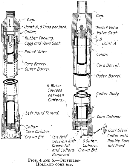
The Oilfields-Holland core bit shown in Figs. 4 and 5 has been used to some extent in California. The advantages of this tool are given by R. M. Barnes in a report to the California State Mining Bureau as follows :
The “core catcher” releases itself with only a slight downward movement if frozen.
The inner barrel will not turn, which is an improvement over the “Holland” bit for use with the stratameter.
The head facilitates removal of the core, as when the cap is removed at point A, the inner core barrel projects above the outer core barrel. In the most recent design, the top of the inner core barrel is made flush with the top of the outer barrel.
The construction of the cutting bit in the “Holland” type was retained because the core does not wash away as easily as in the “Oilfields” type. The water courses are outside of the cutting teeth instead of inside.
Improvements have been made in the combined “Oilfields- Holland” bit which calls for much heavier construction than that used in previous bits because of the strenuous requirements imposed by deep rotary holes and tough formations. Of course the core barrel may be made of any length, but practice has shown that a core longer than 2 ft. is not essential and usually can not be secured.
It might be pointed out that the R. & H. coring tool possesses the following advantages over the Oilfields- Holland tool:
The Oilfields-Holland tool goes to the bottom of the hole open and the core barrel may become partly filled with debris on the way down.
In the Oilfields-Holland barrel, the core must move upward against pump pressure.
The core catcher of the R. & H. tool is much more positive in its action and would be more certain of retaining a core of soft material.
KNAPP CORE BARREL
This tool, invented by I. N. Knapp, is described by R. E. Collom in a report to the California State Mining Bureau as follows:
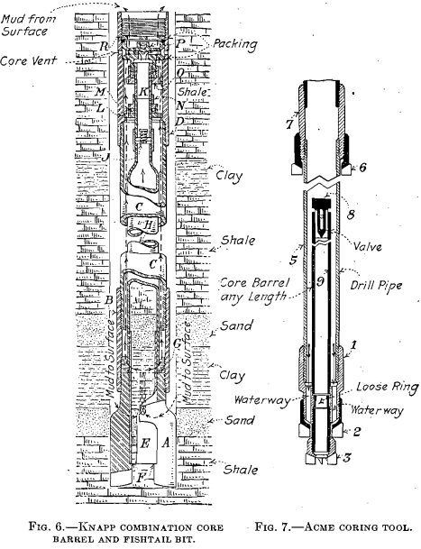
This tool has been operated successfully in ordinary rotary drilling, taking cores of both soft and hard formations. As much as 16 to 18 ft. of hole has been made in one run, giving 12 to 14 ft. of core, in pieces, with a maximum length of 18 in. Fig. 6 is a sectional view of the apparatus complete. A is an ordinary 11-in. fishtail bit with 6-in. shank bored out to 4-in. pipe. B is an ordinary 6-in. drill coupling. C is a 6-in. drill pipe. D is a special drill coupling that supports and swivels the core barrel and is provided with vent holes to equalize the pressure on the core. E is a piece of 4-in. pipe forming the lower end of the core barrel. It is held from dropping through the bit by the offset F, in the bit A; and from pushing up, by the ring G. H is the main core barrel made of a joint of 4½-in. pipe swaged to 2½ in. at the top and on this is attached a 2½-in. coupling. J is a back pressure valve. K is the swivel pipe. L is a perforated annular ring that supports the core barrel. M is a ball-bearing supported on L, carrying the coupling attached to the swivel pipe, thus supporting the core barrel. N is a coupling supporting swivel pipe and core barrel. O is a packing box. P is the head through which the core barrel is vented to the ascending fluid. R is a perforated follower to hold P in place.
One disadvantage is that the barrel is likely to become partly filled with debris before coring starts; also, the fluid nozzle is about a foot too far away from the cutting edge of the fishtail bit to obtain the best drilling effect.
FUTURE OF REAMING-TYPE CORING TOOLS
The Acme bit, which is made in Shreveport, La., is shown in Fig. 7. The writer is not familiar with its use but simply shows it as another type of coring tool.
Coring tools of the reaming type probably will come into much more general use in the Gulf coastal fields within the next few years. Holes can be made just as fast with them as with a fishtail bit. It is not at all impossible that soon these tools will displace fishtail bits altogether in territory where accurate samples of any kind are needed. For coring soft formations, their superiority over other devices cannot be questioned and when tools of this kind are used with rotary drilling equipment the formation samples are superior to those obtained in cable-tool drilling.
Discovery of Palladium
Palladium was originally made known to the public by an anonymous handbill which was circulated in London, announcing that palladium, or new silver, was on sale at Mrs. Forster’s, and describing its properties. Chenevix, in consequence of the unusual way in which the discovery was announced, naturally considered it as an imposition on the public. He went to Mrs. Forster’s, purchased all of the palladium in her possession, and set about examining it, prepossessed with the idea that it was an alloy of some two known metals. After a laborious set of experiments, he considered that he had ascertained it to be a compound of platinum and mercury, or an amalgam of platinum, made in a peculiar way which he describes in a paper read at a meeting of the Royal Society.
Soon after this publication, another anonymous handbill was circulated, offering a considerable price for every grain of palladium made by Mr. Chenevix’s process, or by any other process whatever. No person appearing to claim the money thus offered, Doctor Wollaston, about a year after, in a paper read to the Royal Society, acknowledged himself to have been the discoverer of palladium, and related the process by which he had obtained it from the solution of crude platina in aqua regia, incident to his process of manufacturing platinum. There could be no doubt, after this, that palladium was a peculiar metal, and that Chenevix, in his experiments, had fallen into some error, probably by inadvertently employing a solution of palladium instead of a solution of his amalgam of platinum, and thus giving the properties of one solution to the other.
