
Autogenous and semi-autogenous grinding have experienced renewed interest as efforts to reduce operating and capital costs have increased.
As a result, the mill operator is faced with new equipment perhaps ten times as large as was common in the sixties and new circuit designs with different operating characteristics. No longer can he grab a handful of mill discharge to estimate the size distribution and viscosity or cut a liter sample to determine the pulp density. The operator is separated from the mill discharge by a sump or screen 5 or 6 meters across. He is fortunate if he can even see what is coming out of the mill, let alone get a reasonable sample. The sound and feel of the mill has changed. The ampere meter on the drive motor is probably a hundred meters away in a control room. Figures 1 and 2 illustrate typical grinding circuits and instrumentation. What, then, can we in the Engineering and Construction Industry provide the operator to assist him in operating the circuit somewhere near its maximum efficiency?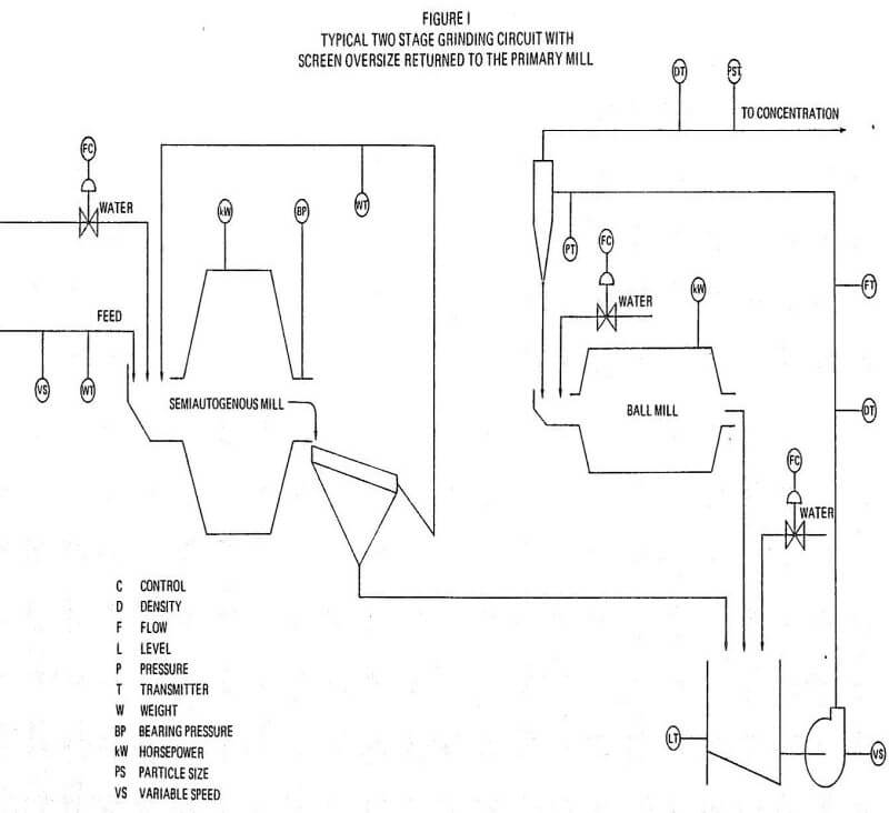
To answer this question, let us redefine the goal of the mill operator. The goal of the operator is to optimize performance of the grinding circuit in terms of maximum tonnage, lowest cost per ton and more uniform feed to the subsequent concentration step.
Once the circuit has been designed and installed, the operator is left with few variables under his direct control that can be used to influence the hour to hour and minute to minute operation of the circuit. These variables are the rate of addition of new feed to the mill, rate of addition of water to the mill feed and discharge, and in some cases addition of more grinding media such as steel balls or pebbles.
Of these variables, the water added to the mill discharge is after the fact and only influences the size separation in classification systems. This control should not be considered a grinding control but should be used by the operator to control the particle size of the cyclone overflow.
Another control the grinding operator can often employ is the number of cyclones in the circuit. By increasing or decreasing the number of cyclones in the circuit the operator can influence the pressure drop across the cyclone. This will influence the size separation in the cyclone, the sharpness of the separation and, most probably the cyclone underflow density. Both the size separation and sharpness of separation are also controls of classification and don’t necessarily affect the performance of the grinding mill. Control of the cyclone underflow has a direct impact on the performance of the mill as it is quite often the principal, if not the only, source of feed to the mill and may contain most of the water being added to the mill as well.
Large grinding circuits normally require installation of 5 to 8 cyclones in a single cluster. Control of pressure drop across the cyclone is easily accomplished by providing one or more of the cyclones in the cluster with automatic valves so that they may be added to or deleted from the circuit as operating conditions dictate.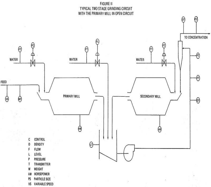
Measurement and control of the rate of addition of new feed and water to the primary mill is relatively easy. Instrumentation is simple, accurate and reliable. If the primary mill is run in open circuit, the only additional information the operator needs to properly control this circuit is the particle size distribution in the mill discharge.
One way of gaining some indication of a change in particle size distribution in the primary mill discharge is to pump the mill discharge to a separate bank of cyclones at a measured or constant flow. If the density of the cyclone feed is measured and controlled by water addition to the mill discharge, a change in particle size in the cyclone feed can be detected by a momentary change in the density of the cyclone overflow. If the density of the cyclone overflow is increasing then more final product is being produced in the primary mill, the ore is getting easier to grind, the secondary mill is receiving less feed and the new feed rate may be increased. Knowing the cyclone feed density and pressure, the particle size split that the cyclone is making can be calculated and controlled on a continuous basis. This will give the mill operator an onstream measurement of the relative grindability of the feed to the primary mill and enable him to recognize and react much more rapidly to ore changes.
Many of the primary grinding mills installed in the last 10 years are very large semiautogenous or autogenous mills. These circuits are much more sensitive to changes in grinding characteristics of the ore than the conventional fine crushing, rod mill-ball mill circuits. The installed power in the primary mill is generally much greater than in conventional circuits. Since the semiautogenous or autogenous mill is dependent at least in part, if not entirely, on the ore to grind itself, a small change in ore grinding characteristics can produce a relatively large change in the grinding capacity of the mill. This may lead to a buildup of critical size material in the circuit.
The critical size of material is determined by many factors and may be anywhere from 100 mm down to coarse sand grains. If the split between the primary and secondary mill is 13 mm and if the critical size is less than 13 mm, it will build up in the secondary circuit and the primary mill must then be run at less than its capacity to keep from overloading the secondary mill. If the critical size is above 13 mm, it will build up in the primary mill circuit filling the primary mill with ore too fine to be effective as grinding media but too coarse to escape to the secondary mill. This will cause the primary mill to lose capacity and the secondary mill to be underfed.
The mill operator then needs some way of balancing the distribution of this critical sized material between the primary and secondary mill as an onstream operating control. This would allow the operator to adjust the workload between the primary and secondary mill as the ore changes so one will not be overloaded and the other underfed. There are several ways this might be accomplished if they are designed into the circuit.
It is common practice on autogenous or semiautogenous primary mills to install a large doubledeck vibrating screen on the primary mill discharge. The screen undersize is pumped to a bank of cyclones in closed circuit with the secondary mill. The screen oversize is returned to the primary mill feed. This allows the operator to see and measure the plus 13 mm circulating load of critical size material. If the secondary mill is a pebble mill, grinding media for the pebble mill may be removed from the top deck of the screen with any excess returned to the primary mill. In some circuits, the screen over-size is put through a short-head cone crusher before it is returned to the primary circuit.
The operator needs a method of changing the split size between the primary and secondary grinding circuits. This could be accomplished by providing the bottom deck of the vibrating screen with a panel on the feed end one meter wide with 20 mm openings. The next meter of the screen might be 13 mm openings and the rest of the bottom deck could be 9 mm openings. Over the top deck but not attached directly to the screen, solid rubber covered panels corresponding to the different sized opening in the bottom deck could be mounted. This is illustrated in Figure III. The discharge from the primary mill could be directed over the top of the solid blanks. These blanks could be easily, inserted in or out of the stream to expose a larger or smaller screen opening depending on the distribution of the particle sizes in the primary and secondary mills.
If the secondary mill is overloaded one or more blank panels may be inserted to bypass the primary mill discharge across the larger openings in the screen and effectively reduce both the top size and volume of new feed to the secondary mill. If the secondary mill is underfed, blank panels may be removed to allow more feed to go to the secondary mill. This will shift more of the grinding load to the secondary mill and perhaps prevent a buildup of a critical size material in the primary circuit. This will allow the operator to have as an operating control a method of distributing the workload between the primary and secondary mills without having to shut down the grinding circuit to change screen sizes.
Another possible method of distributing the work between the primary and the secondary mill is to return a part of the primary cyclone underflow back to the primary mill. This can be accomplished easily if the circuit is laid out to facilitate transportation of the cyclone underflow to either mill.
While this would be less expensive to install than a screen and conveyor circuit, there are several disadvantages which should be considered.
One is the difficulty of moving cyclone underflow over any significant distance. Cyclone underflow is a dense coarse slurry with very few fines and settles out very readily in launders, sumps, pipelines, etc. Slopes and velocities must be kept high, quite often requiring addition of large amounts of water which may interfere with control of slurry density in subsequent operations. Wear on pumps and pipelines can be severe.
The second disadvantage is that the separation in the cyclone is not highly selective. Everything which is not final product reports to the underflow. When this underflow is split between the primary and secondary mill some of the material which is fine enough to be fed to the secondary mill is recycled to the primary mill and some of the coarsest material is fed to the secondary mill. As the primary and secondary mill are designed to perform most efficiently on different sized products, there is some loss of grinding efficiency inherent in this method.
The feed to the secondary mill is normally cyclone underflow. Many attempts have been made to measure the density or volume of this stream on a continuous basis with limited success. Attempts to continuously sample and measure the significant variables of the secondary mill discharge are also open to question. As a result the mill operator is left with the power draw on the secondary mill motor as the only positive measurement of a process variable to guide him in operation and control of the circuit.
If the operator has a mass flow measurement on the cyclone feed and the cyclone overflow, the cyclone underflow can be calculated by difference. This will provide the operator with important information. Knowing the cyclone underflow the operator can control the density and residence time in the secondary mill.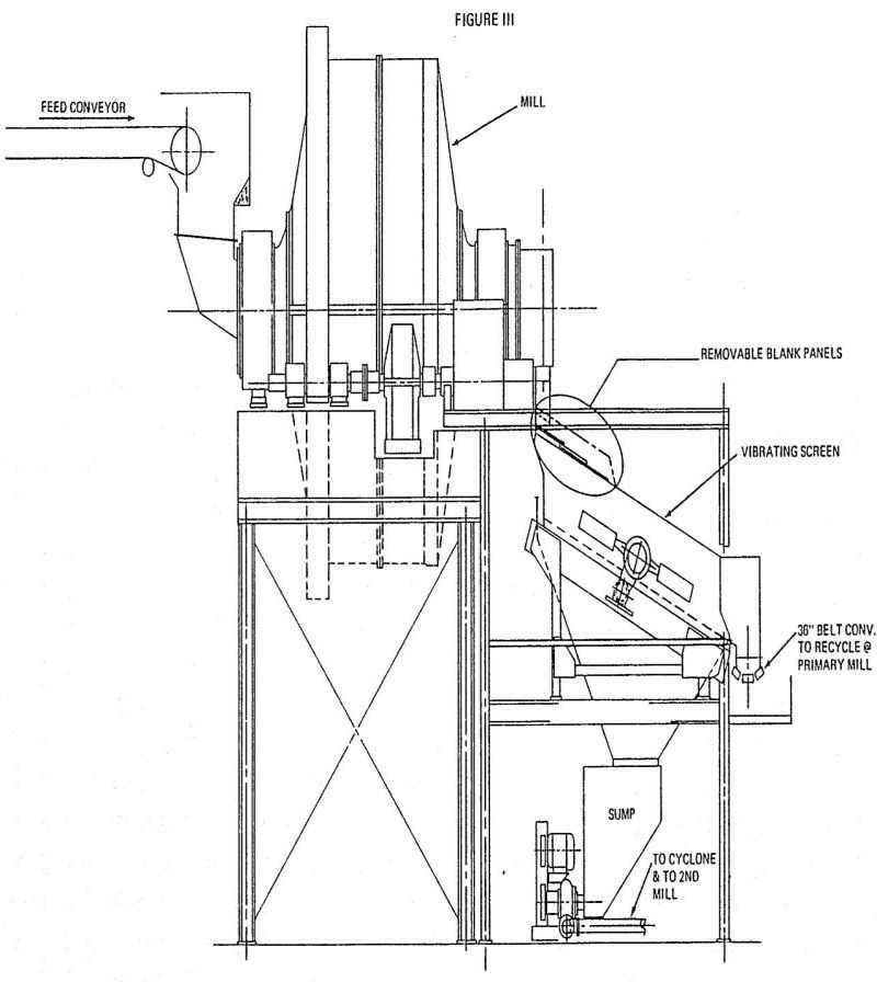
A continuous measurement of the cyclone overflow is a direct measurement of the final product being produced by the circuit. This then can provide the operator with a continuous indication of the performance of the circuit and allows him to recognize ore changes rapidly and evaluate the effect of other changes he may make such as a change in circulating load or mill density.
Measurement of the density and volume of the cyclone feed and overflow enables the operator to calculate and control the size separation the cyclone is making for any given combination of cyclone diameter, feed inlet, apex and vortex dimensions within a fairly narrow range of size distribution in the cyclone feed. If the size distribution in the cyclone feed is changing, it can be detected in the cyclone overflow by a particle size monitor or indirectly by a change in overflow density if sufficient historical data are readily available.
If the operator has measured the cyclone feed and cyclone overflow, he can calculate the cyclone underflow by difference. Knowing the cyclone underflow, the operator can vary and control the density and feed rate of the mill by measured amounts. This will allow the operator to make positive informed responses to changing conditions in the grinding circuit.
It is the objective of this paper to alert the people responsible for the design of these large grinding circuits to the requirements of the operation for a more flexible circuit. Rarely is an ore body or a mining operation so uniform that a single design is optimum for every eventuality. Traditionally, plants have been designed to provide optimum conditions for an average ore which they may rarely see during the actual operation of the plant. Often the actual characteristics of the ore body are not well defined until the mining operation is well underway. It is therefore important in the conceptual design phase of engineering to appreciate the fact that the actual feed to the plant may vary from hour to hour and that the present knowledge of the ore body may not be complete. If some degree of flexibility is not incorporated in the early design of the circuit the operator may be locked into a plant that rarely operates at its optimum capability.