Table of Contents
In belt conveyor application, a pulley’s purpose is primarily three-fold, 1) support the belt in directional changes, as designed in the conveyor, 2) transmit driving power to the belt, and 3) guide or train the belt.
The drive pulley imparts the driving force to the belt and may be located at the head or discharge end of the conveyor, in return strand, or at the tail or loading end of the conveyor.
A snub pulley is located near the drive pulley to provide more arc of contact between the belt and pulley for maximum adhesion in driving the belt.
A head pulley is at the discharge end of a conveyor and in a simple conveyor is normally the drive pulley.
A tail pulley is at the loading end of a conveyor and in a simple conveyor is normally the takeup pulley.
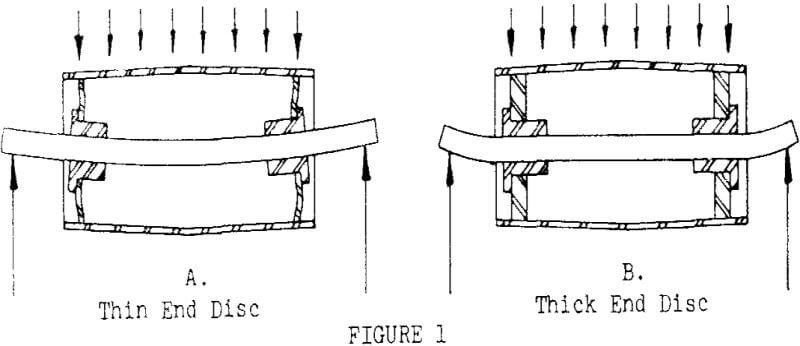
A drum type welded steel pulley design with a solid hub was next introduced which appeared to be an improvement over the arm design. An advantage immediately recognized was the closed-in design using solid end discs, which prevented the entry of material, however, an advantage not immediately recognized, was the in¬creased strength or load carrying ability of this design. This design also allowed for greater flexibility in end disc and rim thicknesses.
Pulley Design Features
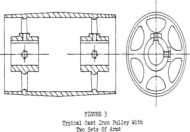
Cast iron pulleys followed the fabricated wood pulley in the progression of design. They were cast in one piece, turned, bored, and furnished keyseated and set screwed, keyseated only, set screwed only or with a plain bore, bronze bushed, with a solid or clamp type hub.
Standard construction for single armed pulleys provided for 65 lbs. effective belt tension per inch-width of face; for multiple arm pulleys 120 lbs. effective belt tension per inch-width of face. After pulley problems developed maximum tension was considered rather than effective tension.
The majority of all pulleys used fall within this standard. The ratings are based on shaft, end disc and rim strength. The equations used to establish these ratings are based on a compromise by committee members of the Mechanical Power Transmission Association at the time this standard was developed.
Other pulley designs, such as, a spun-end disc, magnetic separator, special self cleaning, engineered class high tension, non-rotating shaft, split steel, and motorized pulleys may be furnished, however, these designs do not fell within the scope of the aforesaid standard for welded steel pulleys with a compression hub.
Self cleaning type or wing pulleys as generally referred to, are normally used to prevent material from being forced into the belt and from building up on the pulley face. These pulleys can be straight face or crown and normally have a number of wing plates that extend radially from the longitudinal axis of the hubs and are equally spaced about the pulley circumference.
Pulley Hub Design
There are a variety of hub designs that have been used in belt conveyor pulley design and can be divided into two basic types, solid and compression.
- Solid Hubs – The solid hub design has been with us since the first pulley (Figure 9). The shaft is generally secured with set screws. The hub can be furnished keyseated or plain, dependent upon application. This design is generally preferred in engineered class high tension pulleys for shaft sizes exceeding 10 inches in diameter, however, in this design a press or shrink fit on the shaft is recommended.
- Compression Hubs – The design intent of a compression hub is to provide a compressive gripping force of the hub to the shaft in an attempt to similate a press or shrink fit. A number of the designs are discussed using published trade names.
Shafting
Shaft design plays a major role in the design of a pulley. The structural rigidity of a shaft and pulley require that they be treated as a composite structural assembly. Pulley design considers shaft diameter, however, shaft design is based on the shaft alone without support from the pulley.
Shafts can be subjected to three types of stresses, simple flexure or bending, simple torsion and combined as a combination of bending and torsion. Pulley shafts are subjected only to bending or combined loading. The accepted formula used in determining the diameter of a solid circular shaft in combined bending and torsion is :
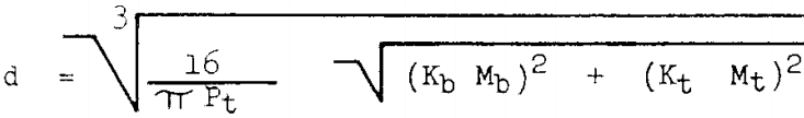
Where:
d = shaft diameter, inches
Kb = service factor for bending, Table 2
Kt = service factor for torsion, Table 2
Pt = shear stress of shaft material, psi Table 3
Mb = bending moment, inch-lbs,
Mt = torsion moment, inch-lbs.
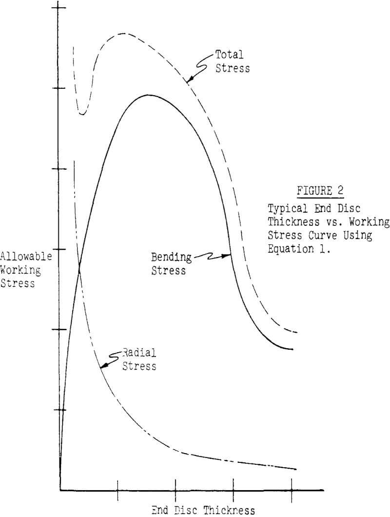
Shaft deflection is best expressed as slope either in degrees or inches per inch. Generally, however, it is expressed in inches per inch and is normally determined at the center of the end disc. Numberous pulley geometries are capable of satisfactory service at various slopes, and specifying maximum shaft slope is not necessarily the best practice. In the past conveyor designers may have specified shaft slopes which they considered as conservative, however, the resulting calculated end disc stress was determine to be too high for satisfactory service.
Pulley Lagging
Lagging is a covering that is applied to the pulley rim. In many applications pulley lagging can improve conveyor performance as well as increase the life of the pulley and the belting. When used on drive pulleys, it increases the coefficient of friction between the pulley face and belt. It is this friction that determines the amount of slack side tension (T2) required in order to prevent slippage between the belt and the pulley when carrying a load, (resulting tension Te).
Belt selection is based on the tight side tension T1 which is the total of T2 + Te. The higher the coefficient of friction, the lower the T2 value and subsequently a lower T1 value. This results in selecting a lighter weight belt.
Lagging also prevents material buildup on the pulley, the belt and the idlers adding extra life to these components. Certain types of lagging called Lorig-Aligner with radial grooves are used to improve severe belt tracking problems and still others types with grooving will allow water to escape the pulley in wet applications.