Table of Contents
- What is Competent Rock
- Classification of Competent Rock
- Physical Properties of Rock
- Assumption Regarding Stress Field
- Assumptions Regarding Criteria of Failure
- Effects of Time
- Safety Factor
- Design of Single Openings in Massive Rock
- Introduction
- Circular Openings
- Elliptical Openings
- Rectangular Openings
- Inclined Openings
- Spherical and Spheroidal Openings
- Design Principles
- Illustrative Problem
- Design of Multiple Openings in Massive Rock
- Introduction
- Row of Circular Openings
- Row of Ovaloidal Openings
- Average Pillar Stress
- Compressive Strength of Pillars
- Illustrative Problem
- Single Openings in Bedded Rock
- Introduction
- Single-Layer Roof
- Two-Layer Roof
- Multiple-Layer Roof
- Rectangular Roof
- Inclined Roof
- Roof Subjected to Gravity and External Forces
- Illustrative Problem
- Multiple Openings in Bedded Rock
- Introduction
- Single-Layer Roof
- Design of Pillars for Multiple Openings
- Illustrative Problem
- In Situ Stress-Strain and Physical-Property Measurement
- Introduction
- Measurement of Stress and Strain
- Measurement of Stress Field
- In Situ Measurement of Physical Properties of Rock
- Data from Mine Surveys
The design and stability of underground openings are problems of paramount importance in mining. Insuring the safety of employees, protecting equipment, mining in a prescribed and efficient manner, and (in mineral mining) achieving an optimum recovery from the deposit depend upon the ability of engineers to design and excavate underground openings that will remain open for a given period.
Although underground mining dates back almost to the beginning of recorded history, the design of underground openings (that is, specifications for size and shape of openings, amount and type of support, and other related problems) until recently has been based on experience gained from trial-and-error methods. Thus, this phase of mining has developed more as an art than a science. The lack of a scientific approach to the problem of design does not reflect inability on the part of the mining profession. The problem has been complicated by many factors, such as lack of an adequate theory describing the stress distribution around a complex system of openings, lack of standardized tests for determining the physical properties of rock, and lack of procedure and instrumentation for making in situ tests to check design validity.
During the last 2 or 3 decades there has been a transition toward a more scientific approach to mining. The stress distribution around single and multiple systems of mine openings has been determined from theory or from photoelastic and rock-model studies. Numerous standardized tests have been established for measuring the strength and elastic properties of rock. Instrumentation and test procedures have been developed for determining the stresses and strains and the in situ strength of the mine rock.
This report reviews and summarizes theoretical and experimental studies of the design of underground openings in competent rock, made by the Applied Physics Laboratory, Federal Bureau of Mines, College Park, Md., and other investigators. Chapters are included on determining the stress around single and multiple systems of underground openings. Design criteria are given for estimating maximum safe roof spans and extraction ratios. Examples illustrating design problems are presented. Finally, procedures for and results from in situ tests and measurements are described.
The design procedures can be applied not only to mineral mining (stope design) but also to the design of highway and railroad tunnels, aqueducts, diversion tunnels (single and multiple), high-pressure penstocks in rock, chambers for the storage of liquid petroleum products, underground warehouses, underground air-raid shelters, and military fortifications. In fact, these design procedures are more important in applications other than mineral mining, because a greater latitude usually is possible in selecting a site in a reasonably competent and uniform rock and in specifying the size and shape of underground openings.
All underground rock is under stress owing to the weight of the overlying rock and to possible stresses of tectonic origin. Any underground opening produces additional stresses in the rocks surrounding the opening, and this rock will fail if the rock stresses exceed the rock strength. Thus, the problem of designing a stable underground opening reduces to determining (1) the maximum stress in rock surrounding the opening and (2) the strength of the in situ rock.
The strength of the in situ rock can be approximated from physical-property tests of drill-core rock specimens from outcrops, the shaft, or early development workings. More accurate information can be obtained from large-scale tests performed in the underground workings.
Determination of maximum stress is complicated by numerous factors, including the effects of heterogeneity in the rock and irregularities in the boundaries, and by a lack of knowledge of the state of stress in the rock before mining. Thus, to determine the maximum stress some limitations and assumptions must be made. These are discussed in the following sections.
This report presents methods and principles useful in designing underground mine openings and pillars in competent rock formations. Two types of formations are considered: (1) Massive formations, in which openings are generally mined with an arched roof, and (2) bedded formations, in which openings are generally mined with a flat roof. Design principles for openings and pillars in massive formations are obtained by considering the maximum tangential stresses developed around single and multiple openings for stress fields of various types. Design principles for openings and pillars in bedded formations are obtained by considering the average stress in pillars and the maximum stresses in roof layers. Experimental procedures for making stress, strain, and in situ physical-property measurements in underground mines to check design calculations are outlined and the results discussed.
What is Competent Rock
Competent rock is defined as rock which, because of its physical and geological characteristics, is capable of sustaining openings without any structural support except pillars and walls left during mining (stulls, light props, and roof bolts are not considered as structural support). Most underground openings for industrial and military uses and most open stopes for mineral mining fall in this category. However, no quantitative means have yet been devised for determining the in situ competency of large rock bodies, except by mining and instrumenting full-scale openings.
It is evident that rock competency cannot be described by terms such as “hard rock” and “soft rock.” Some hard rock, that is, rock that is hard to drill or crush but is highly fractured or jointed, cannot be mined without artificial support. Conversely, soft rock, such as chalk or salt (halite) and the potash and borate minerals, that is relatively free from fracturing and jointing can be mined with large openings. Moreover, physical-property data on the compressive, tensile, or flexural strength of small specimens of rock are not completely satisfactory for estimating the competency of the larger ore bodies from which the specimens were obtained.
Fortunately, a quantitative evaluation of the rock, which can be made from an examination of exploratory drill cores or rock exposures in the shaft or early development workings, frequently is sufficient for appraising the rock competency. These examinations must take into account factors such as the spacing and attitude of joints, fractures, and bedding separations and the type and extent of bond, if any, across the planes of weakness. Evaluation of the rock that will form the boundaries of an opening or specific structural member such as a pillar or the immediate roof is particularly important.
Classification of Competent Rock
A study of the structural stability of underground openings is simplified if competent rock is subdivided into two groups massive and bedded. Massive rock is considered to be elastically perfect, isotropic, and homogeneous and to possess a strength that does not vary appreciably from point to point. Typical examples are massive igneous rocks such as granite, diorite, basalt, and rhyolite; some massive metamorphic rocks such as marble and quartzite; and some sedimentary rocks. For the sedimentary rocks to be included in this class either the bed thickness must be large compared with the roof span or the bonds between thinly bedded rock must not be planes of weakness.
To be classed as bedded rock the rock within each bed, in addition to being elastically perfect, isotropic, and homogeneous, must have a bed thickness that is small compared with the roof span, and the bond between beds must be weak. Most sedimentary rocks and some stratified metamorphic rocks fall in this group.
Identification of the rock and its classification as massive or bedded can be made by examining exploratory drill cores, rock exposures in the shaft, or early development workings.
Physical Properties of Rock
In designing underground openings in either bedded or massive rock the physical properties of the rock must be known. The properties most frequently used are density, Young’s modulus, Poisson’s ratio, crushing strength, and modulus of rupture (outer-fiber tensile strength). Standardized tests for determining these physical properties have been described in previous publications.
If the design is made before any mining, physical-property data can be obtained from specimens cut from exploratory drill cores. Supplementary tests can be made on rock taken from the shaft or early development workings. Usually, the physical-property data from individual drill-core specimens are grouped according to the magnitude of the compressive or flexural strength, and these groups are compared against the geologic log of the exploration hole. This procedure permits a better structural logging of the hole than is afforded by rock identification alone.
Assumption Regarding Stress Field
All underground rock is subject to a vertical component of stress (compressional) due to the weight of the overlying rock. If there is no constraint this vertical stress will expand the rock laterally; if there is constraint lateral stresses (compressional) will develop. In addition, stresses of orogenic or tectonic origin may be present. The direction and magnitude of these stresses will depend on the geologic history of the rock. The components of stress are additive, hence the stresses due to both the weight of the rock and tectonic disturbance form the resultant stress field. The resultant stresses at each point in the rock specify the stress field.
Throughout this report it is assumed that the stress is due only to the weight of the overlying rock, that is, that stresses of tectonic origin are negligible. However, if stresses of tectonic origin were not negligible and the resultant stress field could be determined from under¬ground measurements, all problems in the following chapters could be evaluated, providing the stress field was uniform.
Assumptions Regarding Criteria of Failure
The criterion of failure assumed for design purposes in this report is based on maximum stress; that is, rock will fail in tension when the tensile stress exceeds the tensile strength, as determined by a standardized flexure test (modulus of rupture) on a sample of the rock. If the tensile stress in the rock is small the rock will fail in shear at a value of compressive stress equal to the compressive strength of the rock as determined by a standardized compression test on a sample of the rock. A criterion of failure based on the shear strength is not used, because no satisfactory means has been found to measure the shear strength of rock.
Effects of Time
A roof area or a pillar frequently will remain intact after mining for a period ranging from minutes to years and then fail, indicating that some type of time-dependent deterioration takes place in the rock. Several possible causes have been discussed by other investigators, including failure due to absorption of moisture and a corresponding volume expansion of the rock, crack propagation due to the migration of a corrosive atmosphere such as water vapor into existing cracks, and shearing of bonds between sedimentary layers resulting from a time-dependent rock plasticity.
At present, there is no accepted means of quantitatively measuring this time dependance other than conducting full-scale in situ tests in the underground area. The design considerations presented in this report presume that the strength of the rock is independent of time.
Safety Factor
Because of the uncertainty in determining the in situ rock strength (as distinguished from the strength of a small sample), plus the errors introduced by the various assumptions required to solve problems of design, it is necessary to use a safety factor. In this report the safety factor is defined as the ratio of the breaking stress to the working stress. According to the criteria of failure the breaking stress in tension is the modulus of rupture and in compression the compressive strength. The working stress is the calculated stress in the rock for a given set of structural conditions.
In practice it has been found that safety factors of 2 to 4 are adequate for structural members such as pillars and sidewalls in compression, whereas a safety factor of 4 to 8 is required for members such as bedded roof in tension.
Design of Single Openings in Massive Rock
Introduction
The problem of designing an underground opening in massive rock is one of determining the maximum stresses that will exist in the rock around the opening. These maximum stresses, referred to as critical stresses, must be less than the ultimate strength of the rock if the opening is to be stable and remain open without artificial support.
The magnitude and distribution of the stresses around a single underground opening in massive rock can be determined either analytically or from laboratory model studies, provided simplifying assumptions are made regarding the properties of the rock, the shape of the openings, and the state of stress before mining the opening. In the following discussion it is assumed that:
- Massive rock obeys Hooke’s law and is isotropic and homogeneous with respect to its elastic properties.
- The opening is in an infinite medium. This condition is satisfied if the distance from the opening to an adjacent boundary is greater than three times the dimension of the opening in the direction of the boundary.
- The opening is long compared with its cross section, and the long axis of the opening is horizontal. (for a brief discussion of the stress distributions around openings having three equal or nearly equal dimensions.)
- The cross section of the opening can be represented by simple geometric shapes, such as a circle, ellipse, ovaloid, or rectangle with rounded corners.
- The axes of the cross sections of openings are vertical and horizontal unless otherwise specified. (for a brief discussion of inclined openings.)
- The stress distribution along the length of the opening is uniform and independent of length. For this condition the problem of determining the stress distribution around single openings reduces to one of plane strain and may be solved by considering a hole in a wide plate subject to a uniform two-directional stress field in the plane of the plate.
- The vertical stress on a unit horizontal section of the rock is equal to the weight of rock above the section; thus,
Sv = -ρgZ………………………………………………………(1)
where Sv, is vertical compressive stress, ρg is weight density of the rock, and Z is vertical distance below the surface. - The horizontal stress on a unit vertical section of the rock is given by
Sh = MSv………………………………………………………(2)
where Sh is horizontal compressive stress, Sv is vertical compressive stress, and M is a constant depending on the type of stress field.
Three types of stress fields will be considered in this chapter. These are represented graphically in figure 1 and given algebraically by
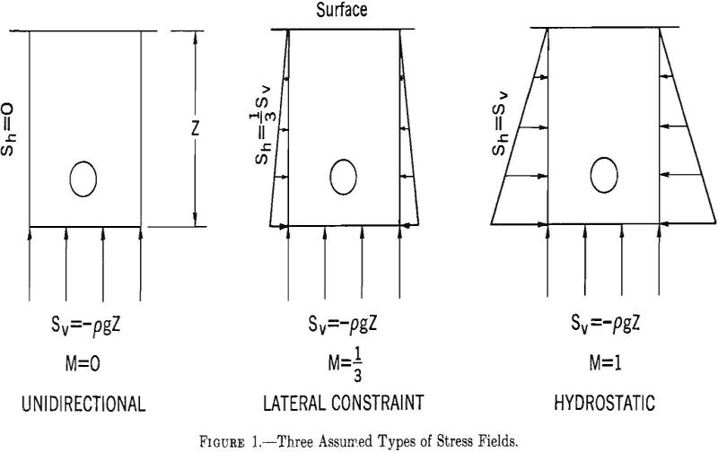
equations 1 and 2, where the value of M is 0 1/3, or 1. The state of stress represented by M= 0 might occur at shallow depths and, or near, vertical free surfaces. The state of stress represented by M= 1/3 might occur over wide ranges of depth. The relation between horizontal and vertical stress for no lateral deformation is given by
![]()
where γ is Poisson’s ratio. When γ is ¼ the ratio of Sn to Sv is 1/3. Thus, the state of stress represented by M = 1/3 corresponds to the condition of no lateral deformation in a rock having a Poisson’s ratio of ¼. The state of stress represented by M= 1 might occur at great-depth or in semiplastic rocks.
Circular Openings
The stresses around a circular opening infinitely far from the boundaries of a plate subjected to a uniform two-directional stress field have been given.
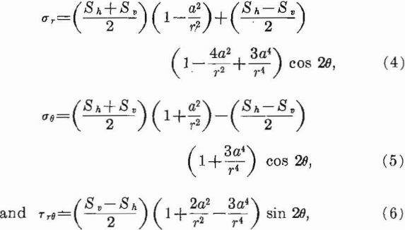
where:
Sh = horizontal applied stress,
Sv = vertical applied stress,
σr = radial stress,
σθ = tangential stress,
Trθ = shear stress,
a = ho e radius,
r=radial distance from center of hole, and
θ = polar coordinate; horizontal axis represents θ = 0°.
Equations 4, 5, and 6 show that the stresses are concentrated on or near the boundary of the opening and are independent of the elastic constants of the material and the radius of the hole. The radius a appears in these equations only in the dimensionless ratio a/r which specifies the distance from the boundary of the hole.
For convenience, the magnitude of the stress near an opening is expressed as a ratio of the
stress at a certain point to the average applied stress outside the zone of disturbance. This ratio is referred to as the stress concentration.
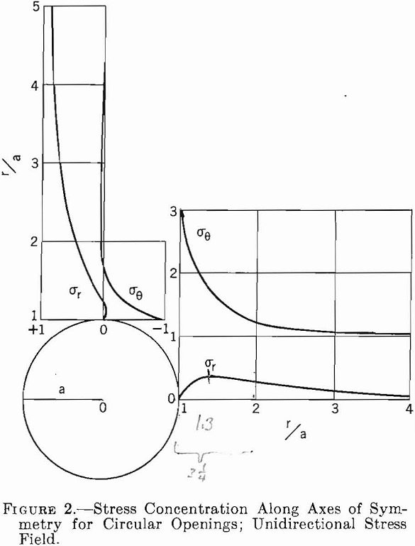
Stress concentrations along the axes from a circular opening in a unidirectional stress field, M= 0, have been calculated from equations 4, 5, and 6 and are shown in figure 2. The figure shows that tangential stresses are a maximum at the boundary of the opening, whereas radial stresses are zero. The maximum shear stress also occurs at the boundary and equals one-half the maximum tangential stress.
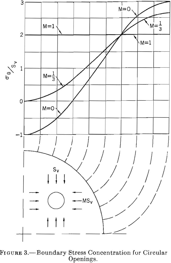
Figure 3 shows the tangential stress distribution around the boundary of a circular opening for stress fields of three types: M= 0, M= 1/3, and M= 1. For M = 0, the maximum boundary stress concentration at θ = 0° is 3 and at θ = 90° is —1. Thus, for an applied compressive stress of —Sv the critical compressive boundary stress is —3Sv and the critical tensile boundary stress +iSv. For M = 1/3 the critical stress concentration is 2 1/3 at θ = 0° and there is no stress at θ = 90°. For M = 1 the critical stress concentration is 2 and occurs at all points on the boundary of the circle.
Elliptical Openings
An elliptical opening can be defined by the following parametric equations:

where p and q are parameters of ellipse, β is the angle, and x and y are rectangle coordinates.
The boundary tangential stress for an elliptical opening in an infinitely wide plate, subjected to a uniform two-directional stress field, has been given.
![]()
where σt is boundary tangential stress, Sh is applied stress in x direction (horizontal), and Sv is applied stress in y direction (vertical).
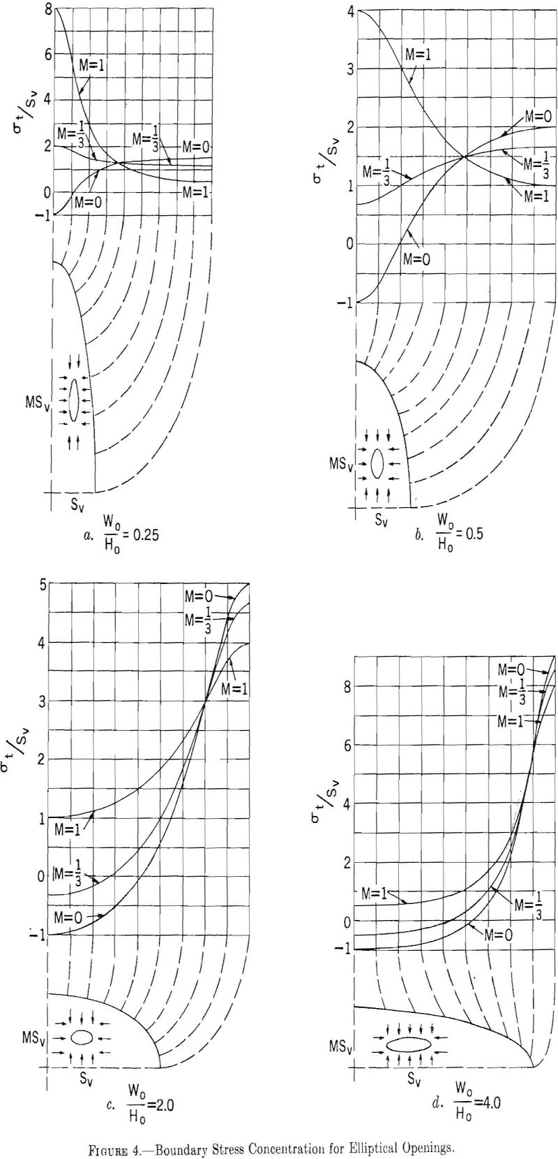
Equation 8 has been used to calculate the boundary stresses around ellipses for four width-to-height ratios, Wo/Ho = p/q = 0.25, Wo/Ho = p/q = 0.5, Wo/Ho = p/q = 2.0, and Wo/Ho = p/q = 4.0 and three types of stress fields, M = 0, M = 1/3, and M = 1. The results of these calculations are shown in figure 4.
For the unidirectional stress field M= 0, the maximum stress concentration at the end of the horizontal axis increases as the width-to- height ratio increases, whereas the stress concentration at the top and bottom of the opening remains constant at a value of minus one, signifying tension when the applied stress is compression. For the two-directional stress field, M = 1/3, the boundary stress concentration at the end of the horizontal axis increases with width-to-height ratio, and the stress concentration at the end of the vertical axis changes from large positive values to small negative values. The hydrostatic stress field produces maximum stresses on the horizontal axis for width-to-height ratios greater than one and on the vertical axis for width-to-height ratios less than one.
Ovaloidal Openings
Ovaloids can be approximated by the following parametric equations:

where p, q, and r are parameters of ovaloid, β is the angle, and x and y are rectangular coordinates.
The boundary stresses for an opening, given by equation 9 in an infinitely wide plate subject to a two-directional stress field, have been given.

where σt is tangential boundary stress, Sh is applied stress in x direction (horizontal), and Sv is applied stress in y direction (vertical).
Using the values of p, q, and r given in table 1, four approximate ovaloidal shaped openings were constructed from equation 9. The boundary stresses around these ovaloidal openings were calculated from equation 10 for three types of stress fields, and the results are shown in figure 5.

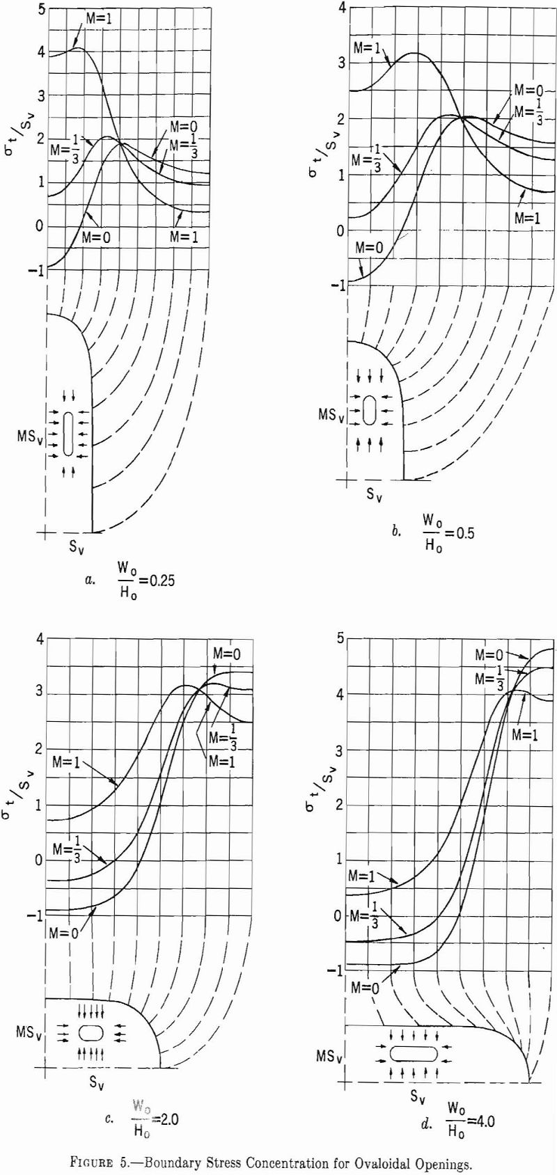
The maximum boundary stresses around approximate ovaloidal openings do not occur on the axes of the opening, as in elliptical openings, but are shifted toward the junction of the semi-circular end and the straight sides.
For the unidirectional stress field, M= 0, the maximum stress concentration along the sides of the opening increases as the width-to-height ratio increases. For all four width-to-height ratios, the stress concentration at the top and bottom of the opening remains approximately constant at a value of minus one. For the two-directional stress field, M = 1/3, the boundary stress concentration on the sides of the opening increases as the width-to-height ratio increases, and the stress concentration at the top and bottom of the opening changes from small positive values to small negative values. The hydrostatic stress field produces maximum stress concentration on the sides of the opening for width-to-height ratios greater than one and on the top and bottom for width-to-height ratios less than one.
Rectangular Openings
Perfect rectangular openings would produce infinitely large stress concentrations at the right-angle corner; therefore rounded or filleted corners are assumed. Normal mining conditions usually will produce a rounded corner in a rectangular opening.
The tangential-stress distribution around a rectangular opening with rounded corners has been studied by the photoelastic method.
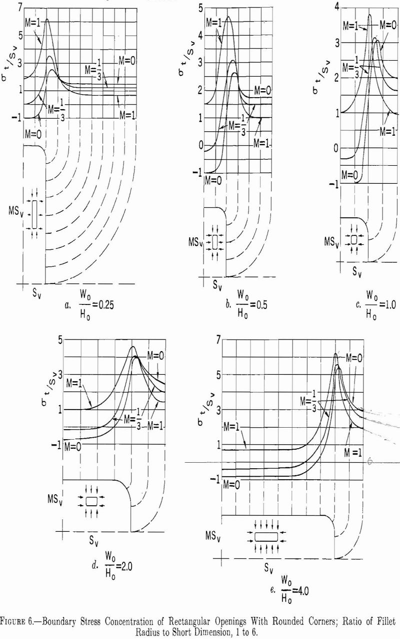
Figure 6 shows the boundary stresses around five rectangles with a constant ratio of fillet radius to short dimension for stress fields of three types.
The stress concentration is maximum at the corners in all instances. For M= 0, this maximum stress increases as Wo/Ho increases. For M = 1/3 or 1, the stress concentration at the corners is a minimum for W0/H0 = 1. For M= 0 or 1/3 a tensile stress is induced in the top and bottom of the opening, but for M= 1 no tensile stresses are induced.
Inclined Openings
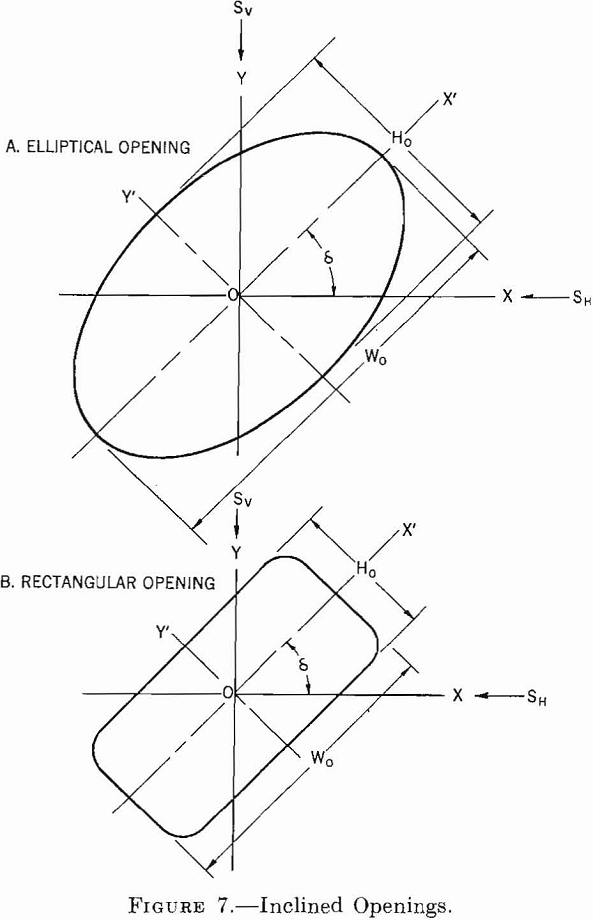
In this section single openings having an elliptical or rectangular cross section are considered, of which the cross-sectional axes are inclined at an angle, δ, to the horizontal and vertical. The length of the opening is horizontal, and the long axis is large compared with the cross-sectional axes.
Figure 7 shows cross sections of an elliptical and a rectangular opening and defines the necessary variables in the problem. The x-y axes, corresponding to the direction of the applied stress field, are horizontal and vertical. The x’-y’ axes correspond to the major and minor axes of the cross section of the opening and are inclined at an angle, δ, with the x-y axes.
The problem of an elliptical opening in a general two-directional uniform stress field has been solved by C. E. Inglis. The equation for the boundary tangential stresses has the form:

where:
α, β = curvilinear coordinates, x’ =c cosh α cos β y’ = c sinh α sin β; β = 0 = the positive x’ axis, β = 90° = the positive y’ axis,
α1 = the constant value of α on the elliptical boundary of the opening,
δ = the angle of inclination of the major axis of the ellipse (the x’ axis) above the horizontal axis (x axis),
Sv, Sh= applied stress in vertical (y axis) and horizontal (x axis) directions.
Panek, using equation 11, has computed critical boundary stress concentrations for three Wo/Ho ratios at various angles of inclination and stress fields of three types: M= 0, and 1. Table 2 summarizes these results. The critical stress concentrations are at the ends of the major and minor axes for δ = 0° or 90°. For other values of δ the critical stress concentrations are near the ends of the major axis.
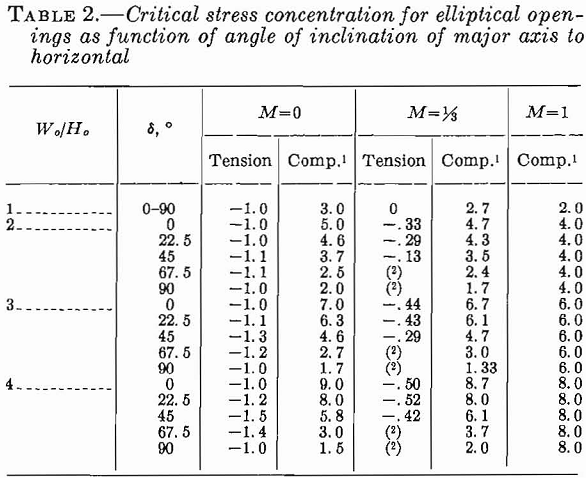
The critical compressive stress concentrations for an applied compressive stress field decrease as the major axis of the elliptical opening is rotated from horizontal to the vertical. The maximum critical tensile stress concentrations for a unidirectional stress field, M = 0, occurs when δ = 45°. For M = 1/3 the critical tensile stress concentrations decrease as the major axis is rotated from horizontal to vertical. For M = 1 there are no critical tensile stress concentrations and the critical compressive stress concentrations are independent of δ.
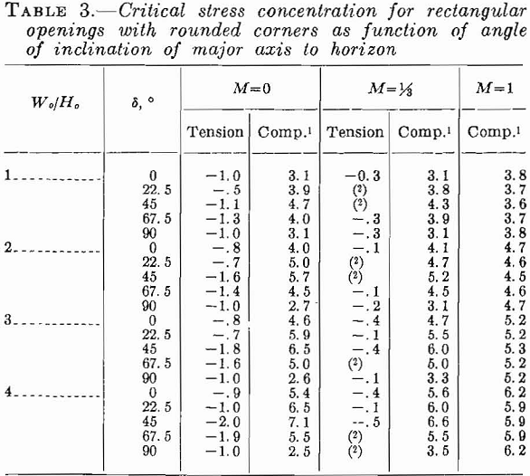
By means of photoelastic studies, Panek has also determined the critical stress concentrations around inclined rectangular openings with rounded corners. Table 3 gives his results for various angles of inclination and ratios of Wo/Ho. The ratio of the fillet radius to the height is 1 to 6.
For M = 0 or the critical compressive stress concentrations are maximum for δ = 45°. For M = 1, the critical compressive stress concentration is virtually independent of the angle of inclination. Critical tensile-stress concen-
trations are large for M = 0 and angles of inclination of 22.5° to 67.5°. For M = 1/3 critical tensile-stress concentrations are small, and for M = 1 they are zero.
Spherical and Spheroidal Openings
In preceding sections of this chapter openings were considered in which the length was large compared with the cross-sectional dimensions. This limitation made it possible to determine the stress concentration on the boundaries of the openings by considering the stress distribution around a hole in the plate. This is a two-dimensional problem.
If the length of the opening is not large compared with the cross-sectional dimensions the problem must be considered in three dimensions. Mathematically, the problem is much more difficult, and only two problems of this type have been solved—the sphere and spheroid. The results of this investigation are too lengthy to include in this report. However, two conclusions that can be drawn from the study follow:
- The stress distributions around spherical and spheroidal openings depend upon the value of Poisson’s ratio, whereas the stress distributions around openings that are long compared with their cross-sectional dimensions are independent of the elastic constants.
- Usually, the maximum boundary stresses around spherical and spheroidal openings are 30 to 40 percent lower than the corresponding maximum stresses around infinitely long openings having the same, cross-sectional shape.
Design Principles
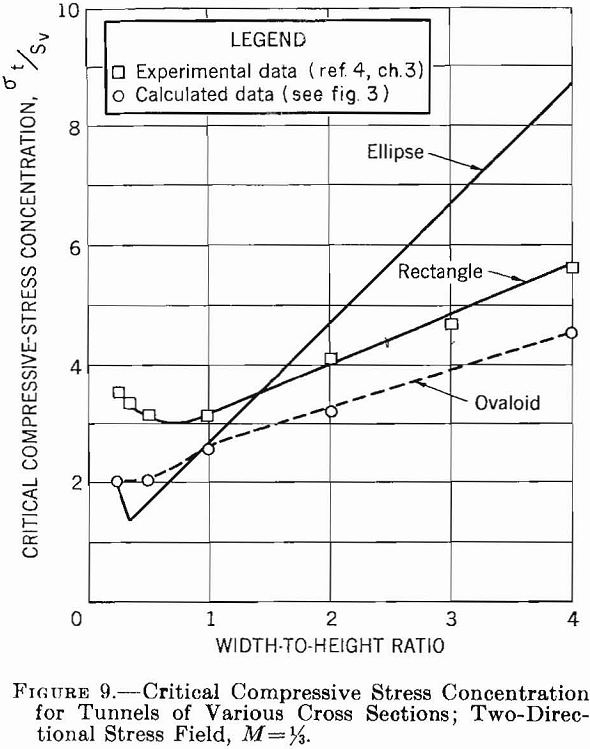
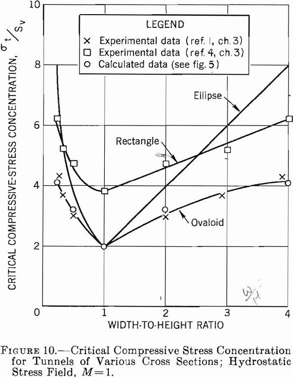
The results of the preceding sections of this chapter are summarized in a set of critical stress curves that can be used in designing single openings in homogeneous isotropic rock formations. Figures 8, 9, 10, and 11 show the variation of critical compressive and tensile stresses with Wo/Ho for elliptical, ovaloidal, and rectangular openings in plates and for the three types of applied stress fields. The curves in these figures can be used to estimate the critical stresses for openings of various shapes in stress fields of different types. Moreover, the following design principles can be obtained from these data.
- If subsurface conditions approximate those of a unidirectional stress field acting vertically, an elliptical-shaped opening with the major axis vertical gives the smallest critical stress. Furthermore, the greater the ratio of major to minor axis, the lower will be the critical stress. However, if an opening is required whose width-to-height ratio is greater than unity, either an ovaloid or a rectangle with rounded corners is a better choice than an ellipse.
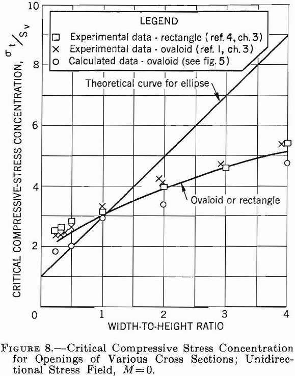
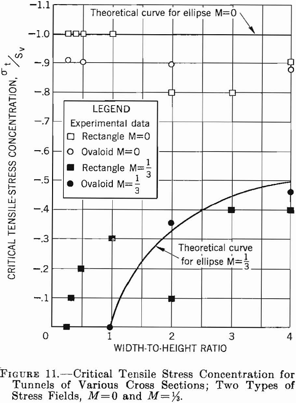
2. With a unidirectional vertical stress field, a stress concentration of approximately — 1 is developed in the roof, that is, the stress in the roof is tension and is equal to the applied compressive stress. As the tensile strength of most rock usually is very low compared with its compressive strength, this tension may be significant.
3. With a two-directional stress field and M equal to approximately 1/3, an elliptical or ovaloidal opening with the major axis vertical induces lower critical stresses than a rectangluar opening. Moreover, the critical stress becomes a minimum when the ratio of major to minor axis is about 1 to 3. If the width-to-height ratio of the opening is greater than unity, ovaloidal or rectangular openings induce lower critical stresses than elliptical openings.
4. In a two-directional stress field with M = 1/3 tension is induced in the roof only when the width-to-height ratio of the opening is greater than unity. Although the tensile-stress concentration is lower at all times than for a unidirectional vertical stress field, the magnitude of the stress increases with an increase in width-to-height ratio and is virtually independent of the shape of the opening.
5. In a hydrostatic stress field, the preferred opening is a circle. When a width-to-height ratio either smaller or greater than unity is desired, an ovaloid will induce lower critical stresses than either the ellipse or rectangle.
6. In a hydrostatic stress field, no tensile stresses are induced for any of the opening shapes.
7. In any type of stress field sharp corners on an opening will produce high stress concentrations and should be avoided.
Illustrative Problem
The problem is to determine the safety factors for the stresses around a long rectangular opening 25 feet wide and 10 feet high at a depth of 900 feet in a uniform massive sandstone bed 510 feet thick and having the following physical properties:
Compressive strength…………………………….lb./in.²………………… —18, 000
Modulus of rupture………………………………..lb./in.²…………………….. 1, 600
Poisson’s ratio………………………………………………………………………….. 0. 25
Rock weight-density………………………………lb./ft.³…………………………. 155
Rounded corners will be assumed for the opening, as routine blasting rarely produces sharp corners. The stress field before mining may be assumed to result only from the weight of superincumbent rock and lateral confinement, thus, M = 1/3. Therefore, from equations 1 and 2, page 8:

The width-to-height ratio for the rectangluar opening is 2.5; therefore, from figure 9, the maximum compressive stress concentration in the sidewalls is 4.4, and from figure 11 the maximum tensile stress concentration in the roof is —0.4. Hence, the critical stresses on the boundary are:
Critical compressive stress= — 970 x 4.4= — 4,300 lb./in.²
Critical tensile stress= — 970 x —0.4 = 390 lb./in.²
The safety factors are the ratio of compressive strength to maximum compressive stress and the ratio of modulus of rupture to maximum tensile stress; thus,
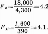
As both safety factors exceed 4, the opening should be stable.
Design of Multiple Openings in Massive Rock
Introduction
This chapter considers the stress distribution around systems of parallel openings separated by rib pillars and room-and-pillar mining systems. The simplifying assumptions, made in section 3.1 regarding openings, rock properties, and state of stress before mining, apply here.
The problem of determining the magnitude and distribution of stresses around multiple openings is more complicated than for a single opening. A single opening in a uniform stress field disturbs the stress field for a distance of approximately twice the diameter from the opening. Thus, when two openings are less than two diameters apart, the stress distribution around one opening affects the stress distribution around the other.
Because of the complexity of the problem only a few examples involving relatively simple shapes have been treated analytically, such as two or three circular openings in an infinite plate or an infinite number of circular openings in an infinite plate. The stress distribution around openings such as ovaloids and rectangles with rounded corners have been determined from photoelastic models.
Row of Circular Openings
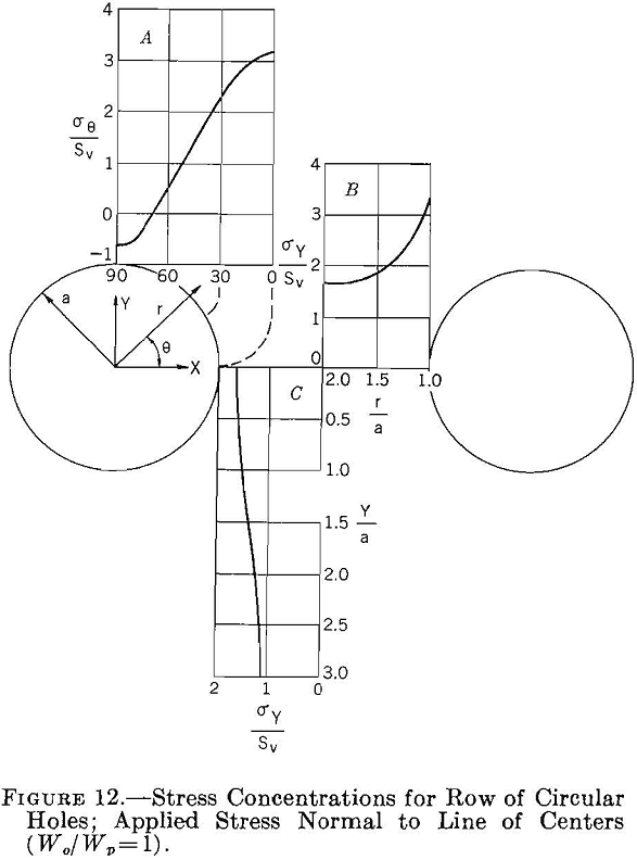
The stress distribution around an infinite row of equal-size circular holes equally spaced in an infinitely wide plate, subjected to either a uniform stress normal or parallel to the line of holes, has been studied theoretically by Howland. The results of this work are summarized in figures 12, 13, and 14. Figure 12 shows the stress concentration around the opening and through the center of the pillar for an applied stress normal to a line through the centers of the holes when the width of the pillar is equal to the width of the opening. Comparing the results given in figure 12 with those in figure 2, page 9, shows that the maximum stress concentration has increased from 3 to 3.26 owing to the presence of the adjacent holes. This increase is comparatively small considering the fact that the average stress on the line of centers is twice that for a single hole in an infinite plate. Thus, one can infer that the average stress in the pillar increases more rapidly than the maximum stress, and that the average stress in the pillar will approach the maximum stress for large stress concentrations.
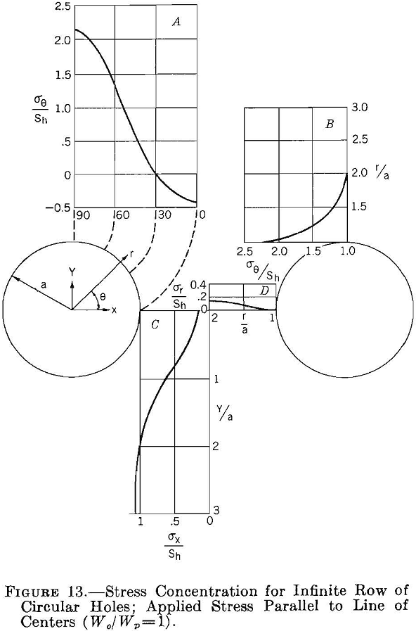
Figure 13 shows the stress concentrations around the opening and in the pillar when the applied stress is parallel to the line of centers and Wo/Wp = 1. Comparing figures 13 and 2, p., shows that in a row of circular holes one hole shields another, so that the concentration of stresses around the row of openings is less than that around a single circular opening. For a row of circular holes and applied stress parallel to the line of centers the critical boundary stress concentrations are +2.16 and -0.39, compared with +3.0 and -1.0 for a single circular hole. Moreover, the stress concentration in the pillar is relatively small, as shown in figure 13, curves C and D.
Curves A in figures 12 and 13 can be combined to determine the boundary stress concentration around a row of circular holes spaced 1 diameter apart for a two-directional applied stress field. The results of these calculations are given in figure 14 for M = 0, 1/3 and 1. Comparing figures 14 and 3 (p. 10) shows that the maximum boundary stress concentrations on the sides of the holes are larger and on the top and bottom smaller for a row of circular holes than for a single opening.
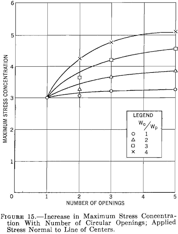
Experimental photoelastic data on the stress concentration around a row of a finite number of circular holes in a plate are given in figure 15. The shape of the curves in figure 15 indicates that as the number of openings increases the maximum stress concentration asymptotically approaches an upper limit. This upper limit corresponds to that for an infinite row of holes. For five circular holes spaced 1 diameter apart the maximum stress concentration is 3.28, whereas the theoretical solution for an infinite row of holes is 3.24. These values agree within the experimental error of the data.
Row of Ovaloidal Openings
Stress distributions around a row of five ovaloidal holes in a plate subjected to a uniform stress normal to the line of holes has been studied by the photoelastic method. This study showed that the following generalizations can be made regarding the stress distribution

around systems of equal-size openings equally spaced in a undirectional compressive stress field:
- The maximum boundary compressive stresses occur on the sidewalls of the openings, that is, along the edge of the rib pillars between the openings.
- The boundary stress at the top and bottom of the opening is tension and is approximately equal in magnitude to the applied stress. However, this tensile stress concentration decreases rapidly with applied confining side pressures.
- The pillar stress concentration increases with increasing opening-to-pillar width ratios, but the stress distribution in the pillar becomes more uniform. Thus, the average stress in the pillar is nearly equal to the maximum stress for opening-to-pillar width ratios greater than 4.
- As the number of openings in a row increases the maximum stress concentrations in the central pillars approach an upper limit. This upper limit corresponds to the stress concentration for an infinite row of openings, and for practical purposes five openings or more are considered an infinite number.
The following equation has been derived from experimental data (1):

where:
K = maximum stress concentration in pillars,
c = maximum stress concentration around a single opening for a unidirectional stress field,
Wo = width of the opening, and
Wp=width of the pillar.
Equation 12 can be used to compute the maximum stress concentration in rib pillars for a series of parallel openings. Values of c for different-shaped openings can be obtained from the curves in figure 8, page 16. Equation 12 has been evaluated for circles and ovaloids having height-to-width ratios of 0.5 and 2.0, and the corresponding maximum stress concentration in the pillars as a function of opening- to pillar-width ratio is shown in figure 16, together with the experimental data. Figure 16 also shows the average pillar stress concentration as a function of W0/Wp. The average pillar stress is obtained by assuming that any one rib pillar uniformly supports the weight of the rock overlying the pillar and one-half the opening on each side of the pillar. Thus,

where:
Sp = average pillar stress,
Sv = applied vertical stress,
Wo = width of opening, and
Wp = width of pillar.

Analytical studies of the stress distribution around a row of ovaloids in a two-directional stress field are inadequate for obtaining design criteria directly. The results for an infinite row of circular holes in a two-directional stress field show that confining pressures applied from the side are very effective in reducing the tensile stresses at the top and bottom of the circular openings but reduce the stress concentration in the pillars very little. If it is assumed that a row of ovaloidal holes will behave similarly, equation 12 can also be used as the design formula for applied stress fields corresponding to M= 1/3 and M= 1.
Average Pillar Stress
Theoretical and experimental studies of stress distribution around a row of equal-size, equally spaced openings have shown that as the opening- to pillar-width ratio increases the stress distribution in the rib pillar becomes more uniform, so that the average stress approaches the maximum stress. This result is very significant because it implies that average stresses in pillars can be used as a first approximation of the pillar stress in any underground design problem. Because average pillar stress will play an important role in underground design problems it seems appropriate to discuss briefly its calculation under various conditions.
The basic support for a system of underground openings is the unmined rock left between the openings and around the system of openings. If the system is mainly horizontal in extent, a horizontal plane through the openings will be composed of two areas—a mined area and an unmined area. If the assumption is made that the pillars uniformly support the entire load of rock overlying both the pillar and mined area, the average pillar stress is related to the applied stress by

where
Sp = average pillar stress,
Sv = average applied stress = -pgZ,
Am = mined area,
Ap = pillar area,
At = Am+Ap = total area,
pg = weight-density of the rock, and
Z = depth from surface to opening.
Thus, the average pillar stress can be obtained from a plan of the system of openings by measuring the pillar area and the total area enclosed by the solid rock. If the openings are of equal size and are equally spaced, the total area and pillar area can be calculated from the dimensions of the openings and pillars.
For a system of parallel openings separated by N rib pillars, where the width of the openings is W0, the width of the pillars is Wp, and the length of the openings and pillars is Lp, the mined area is given by
Am = LpWoN……………………………………………………(16)
and the pillar area is given by
Ap = LpWpN…………………………………………………..(17)
Thus, equation 15 for a system of parallel openings separated by rib pillars becomes

For a room-and-pillar system of mining comprising square pillars of width Wp in both directions having opening widths of Wo in both directions, the total area enclosed by solid rock for N square pillars is
At = (Wo + Wp)²N…………………………………………………..(19)
and the pillar area is
Ap = Wp²N…………………………………………………………..(20)
Thus, equation 15 for a room-and-pillar system using square pillar support is

Equations 14, 18, and 21, expressed as a function of the extraction ratio R, become
![]()
The extraction ratio, R, is given by

Equation 22 may be rewritten as a design formula for safe pillar support by replacing Sp by Cp, the compressive strength of the pillar, dividing Cp by F, a safety factor, and solving for R, the extraction ratio. Thus,

Compressive Strength of Pillars
The compressive strength of a pillar, Cp, used in equation 24 needs clarification. Standardized tests for determining the compressive strength of rock are made on drill-core specimens having a height-to-diameter ratio of 1. However, the compressive strength of a specimen depends on the height-to-width ratio, and the following equation has been found to hold for specimens having a height-to-width ratio of 0.5 to 2.0:
![]()
C1 = compressive strength for specimen having d/h = 1,
Cs = compressive strength of specimen with d/h ≠ 1,
d = diameter of specimen, and
h = height of specimen.
In this report it is assumed that the compressive strength of a pillar, Cp, is equal to the compressive strength of a specimen having the same height-to-diameter ratio. If the height-to-diameter ratio of the specimen is not the same as that of the pillar, equation 26 can be used to correct for specimen size.
The strength of underground pillars in stratified formations presents some difficulties, because the strength of various strata of rock in the pillar differ greatly. Unpublished laboratory tests have shown that the strength of pillars composed of different strata of rock usually is more nearly equal to the average strength of the various strata of rock rather than to the strength of the weakest stratum. Therefore, the compressive strength of pillars in stratified formations can be approximated by averaging the compressive strength of the various types of rock in the pillar.
Horizontal planes of weakness in a pillar do not affect the pillar strength appreciably. Unpublished laboratory data have shown that a pillar composed of two sections, each having h/d = ½, has the same strength as a single pillar having h/d= 1.
Illustrative Problem
- The problem is to determine if a row of 30- foot-diameter circular tunnels can be spaced safely on 45-foot centers at a depth of 800 feet in a massive rock formation having the following physical properties:
Weight-density lb./ft.³…………………………………….162
Compressive strength lb./in.²……………………….15, 000
Modulus of rupture– lb./in.²……………………………800
Poisson’s ratio……………………………………………….0.25
Lateral constraint is assumed; therefore, the applied stress field is
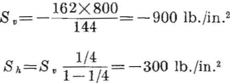
The opening- to pillar-width ratio is 30/15 = 2, and the critical stress concentrations for a circle are 2.67 in compression and 0 in tension. Substituting these values in equation 12 gives
K = 2.67 + 0.09[(2+1)²-1]=2.67 + 0.72= 3.39.
A stress concentration of 3.39 gives a critical compressive stress of 3.39 x -900= -3,050 lb./ in.² The ratio of compressive strength to critical stress is 15,000/3,050 = 4.9. As the safety factor is greater than 4 the system of openings should be stable. - The problem is to determine the maximum safe extraction ratio for a room-and-pillar system of mining in a flat-lying ore body at a depth of 1,100 feet in a massive rock having the following physical properties
Weight-density lb./ft.³………………………………………….150
Compressive strength . _lb./in.²……………………..—20,000
Modulus of rupture lb./in.²…………………………………..700
Poisson’s ratio……………………………………………………0. 25
With a room-and-pillar system of mining the best method of design is obtained by considering average pillar stress. The appropriate design formula is equation 24. The applied vertical stress at 1,100 feet is

Using a safety factor of 3, equation 24 gives the extraction ratio as

Single Openings in Bedded Rock
Introduction
The theory and procedure for designing single underground openings in bedded rock are discussed in this chapter. As defined in chapter 2, page 5, only formations in which the rock is divided into beds that are thin compared with the span of the openings and in which the bond between beds is weak are considered in this class. Where the ratio of the span of the opening to the thickness of the beds is 5 to 1 (or less) or where the beds are strongly bonded, the procedures outlined in chapter 3 should be followed. Chapter 3 should also be used for bedded rock if the roof of the opening is curved or arched; however, the solution of the design problems of this type is less accurate. It is also assumed that the stress in sidewalls of a single opening in bedded rock is the same as that for massive rock and can be computed by the procedures given in chapter 3.
In most mine openings in bedded rock the roof is formed at a bedding plane and is relatively smooth and flat. Furthermore, because of the weak bond between beds, the roof rock will either immediately, or after a time, become detached from the overlying rock and form a layer (or layers) that is loaded only by gravity. This layer (or layers) is called the immediate roof, and the overlying roof is called the main roof. The stresses in the main roof can be computed by the procedures outlined in chapter 3. The stresses in the immediate roof can be computed from the theory of a clamped beam or plate, provided that:
- Within each layer the thickness is uniform.
- The flexure of the beam or plate is caused by gravity; that is, there are no end thrusts or other external forces.
- The rock in the layers is elastically perfect, isotropic, and homogeneous.
- The ends of the layers are rigidly clamped by overlying rock and the sidewall.
Assumption 3 precludes the possibility of any fracturing in the roof. However, in a room that is long compared with its span, vertical fractures normal to the length of the room will not increase the stress in the roof significantly.
The problem of design reduces to the computation of a roof span for a selected working stress. For roofs that are long compared with their span (2:1, or more) beam theory is used; for ratios less than 2 to 1, plate theory is used.
The design procedure is considered for roof layers of two classes, namely, horizontal and inclined. The stress in a roof layer inclined 10° or less is only slightly lower than stress in a horizontal layer and is considered as horizontal. The effect of external forces, such as air, gas, or water pressure and end thrusts, is also considered.
Single-Layer Roof
The maximum values of the deflection, shear, and tension for a horizontal, uniformly loaded roof layer clamped at both ends have been given
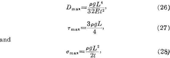
where
Dmax = maximum deflection,
σmax = maximum tensile stress,
Tmax = maximum shear stress,
L = span of roof layer (shorter lateral dimension of layer),
t = thickness of roof layer,
E = Young’s modulus, and
pg = weight-density of rock.
The maximum deflection occurs at the center of the layer and the maximum compressive, shear, and tensile stresses occur at the ends of the layer. Because rock is much weaker in tension than compression, only the tensile and shear stresses in the rock layers are considered. At the center of the layer the shear is zero, and the tension is one-half the maximum value. Thus, the expected points of initial failure would be at the ends (top side of the layer) of the span.
The maximum shear stress varies directly as the span, whereas the maximum tensile stress varies directly as the square of the span and inversely as the slab thickness. The ratio of these stresses is:
σmax/Tmax = 2L/3t……………………………………………….(29)
Thus, if the span-to-thickness ratio is greater than 5 to 1, the tensile stress is more than three times the shear stress. As the tensile strength of rock usually is less than the shear strength, shear stresses can be disregarded in determining span.
Equation 28 may be rewritten as a design formula for the roof span by replacing σmax with T, the modulus of rupture (outer-fiber tensile strength) of the rock, dividing T by F, a safety factor, and solving for L; thus,

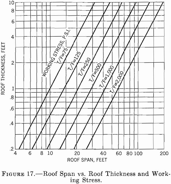
Figure 17 shows a graph of equation 30 on log-log coordinates, using a rock-weight density of 0.09 lb./in.³ This graph relates the span to bed thickness and working stress.
Two-Layer Roof
With immediate roof consisting of two layers there are two cases to consider. When the thicker layer overlies the thinner layer, each acts independently, and the stresses and deflection in each layer can be calculated by equations 26, 27, and 28. When the thinner layer overlies the thicker layer the lower layer is loaded by the upper one; the additional loading can be calculated and represented as an equivalent increase in the weight-density of the lower layer (1). Thus,

pag = adjusted weight-density of lower layer,
E1 = Young’s modulus of lower layer,
E2= Young’s modulus of upper layer,
p1g= weight-density of lower layer,
p2g= weight-density of upper layer,
t1 = thickness of lower layer, and
t2 = thickness of upper layer.
The maximum values of the deflection, shear, and tensile stress in the lower layer can be calculated from equations 26, 27, and 28, respectively, by replacing p1g with pag. If the density and Young’s modulus are the same for both layers, the maximum value of pag is equal to 4/3 p1g and occurs when the upper layer is one-half the thickness of the lower layer. Thus, the maximum stress in the lower layer is 33 1/3 percent greater than the gravity stress in the lower layer.
Multiple-Layer Roof
When the immediate roof consists of three or more layers and the thinner layers overlie the thicker ones, the additional load on the lowest layer can be determined by calculating an adjusted weight-density of the lowest layer (2); thus,

where
pag = adjusted weight-density of lowest layer,
En = Young’s modulus of nth layer,
png = weight-density of nth layer, and
tn = thickness of nth layer.
The values of the maximum deflection, shear, and tensile stress and the design equation are again obtained by substituting pag for p1g in equations 26, 27, 28, and 30, respectively.
For multilayered roofs having various thicknesses and physical properties, the number of layers that need to be considered can be determined by using equation 32 stepwise; that is, the apparent weight-density is calculated for the first two layers, the first three, the first four, etc., until the adjusted weight-density shows no further increase. Only layers that produce an increase in the adjusted weight-density load the lowest layer.
Rectangular Roof
The maximum values of the deflection and tensile stress for a uniformly loaded rectangular roof layer (plate) clamped on all edges have been given:

where:
Dmax = maximum deflection,
σmax = maximum tensile stress,
a = shorter lateral dimension,
b = longer lateral dimension,
E= Young’s modulus,
pg = weight-density,
t = thickness, and
A, B = constants.
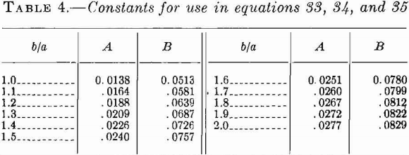
Table 4 gives the values of A and B for various values of b/a and Poisson’s ratio equal to 0.3.
The maximum deflection occurs at the center of the layer and the maximum tensile stress at the end of the longer dimension at the upper edge of the layer. For ratios of b to a greater than 2, the maximum stress and deflection computed from equations 26 and 28 for a beam approximate the stress and deflection computed from equations 33 and 34 for a plate. The difference in the maximum stress is less than 1 percent, and the difference in the maximum deflection is less than 12 percent.
As before, equation 34 can be rewritten as a design formula by replacing σmax with T, dividing T by a safety factor, F, and solving for a, the shorter lateral dimension. Thus,

Inclined Roof
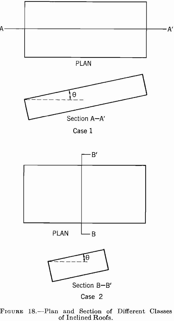
Two types of inclined roof are considered in this section: (1) Where the long axis of the roof is inclined and the short axis (span) is horizontal and (2) where the long axis is horizontal and the short axis is inclined. (See fig. 18.) In each type the angle measured between the roof and the horizontal is designated by θ. It is assumed that the stress in the roof layers is due to flexure caused by gravity. For either type the maximum stress is given by
![]()
Equation 36 can be rewritten as a design equation by the same procedure used for the horizontal roof layer. Thus,

For large angles, if there is a lateral thrust, equations 36 and 37 do not hold.
Roof Subjected to Gravity and External Forces
An added load may be imposed on a roof layer by gas or water pressure. If this pressure is considered as an added load on the layer, the maximum tensile stress and deflection become

where P = pressure due to air, gas, or water pressure on the layer.
Equation 38, rewritten as a design equation, becomes

For a rock having a weight-density of 0.1 lb./in.³ and a roof layer whose thickness is 10 inches, a gas or water pressure of 1 p.s.i. will double the stress in the layer. Because a roof layer is very sensitive to hydrostatic or pneumatic pressures, suspected areas should be carefully checked. Usually the pressure can be relieved by drilling holes through the layer.
A stress applied to the ends of a roof layer is additive to the flexural stress in the layer owing to gravity hence, a compressive end stress on a roof layer decreases the maximum tensile stress and increases the maximum compressive stress in the layer. For end stresses of 1,000 p.s.i. or less, the computed compressive stress and tensile stress are within the strengths for most rocks; therefore, equation 30, page 24, can be used for the design of roof layers with end stresses. In fact, because the ratio of the critical stress to the working stress for most thin roof layers is much lower for tensile stresses than for compressive stresses, the use of equation 30 for design gives an added margin of safety.
Illustrative Problem
The problem is to determine the safe span for a three layer gravity-loaded roof over single underground openings in a bedded formation. The thicknesses of the roof layers and the physical properties of the rock are as follows:

The second layer, because it is thinner, will load the bottom layer, but the third layer will not load either the first or second layer. The apparent weight-density of the bottom layer is

Substituting pag for pg in equation 30 and using a safety factor of 6, the safe span is

As the ratio of span to thickness is greater than 5 to 1 the use of equation 30 or 35 (for beam or plate) is justified. If the room length were greater than 66 feet (that is, the length- to-span ratio was greater than 2 to 1) use of equation 30 would have been justified. If the room length were less than 66 feet, the span should have been estimated using equation 35.
Multiple Openings in Bedded Rock
Introduction
This chapter considers the design principles for multiple openings in bedded rock. The general assumptions in chapter 5 regarding the planes of weakness of the rock, its physical properties, the state of stress before mining, and the geometry of the openings apply to this chapter.
The roofs of the openings are considered to be smooth and flat, and the roof rock is separated into gravity-loaded layers that are thin compared with the widths of the openings. The procedures given in chapter 4 should be used for multiple openings in which the beds are thick compared with the widths of the openings, the planes of weakness are far apart, or the surfaces are curved or arched. For multiple openings that are long compared with their span and are separated by rib pillars, the roof design is about the same as that for single openings of the same type and will be reviewed briefly in this chapter. The roof design for a system of openings supported by square or rectangular pillars is more complicated. The stresses in the roofs can be computed from the theory of slabs clamped by supporting columns.
The vertical section of the opening is considered to be square or rectangular, and the horizontal plan of the pillar is square or rectangular. It is assumed that the horizontal planes of weakness in the pillars do not change the stress distribution owing to vertical compression, that the small differences in the strength of the rock from bed to bed do not change the overall pillar strength significantly, and that the average compressive strength can be used as a basis for design.
Single-Layer Roof
For rows of parallel openings separated by rib pillars, the stress concentration in the main roof decreases as the distance between the openings decreases. (See ch. 4, 3, p. 22.) Moreover, the stress concentration in the main roof is small compared with the stress in the immediate roof owing to flexure; therefore, equation 30 (p. 24) can be used for design.
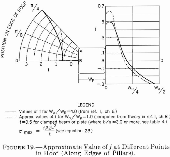
The design of roofs for multiple openings supported by regularly spaced pillars is more complex. The stress problem for a plate (roof layer) clamped and supported by randomly spaced columns (pillars) has no known theoretical solution. The stress problem for a plate clamped (and supported) by regularly spaced square columns with rounded corners has been solved. This problem can be considered representative of a roof layer supported on regularly spaced pillars. For the square pillar, the stresses in the layer are maximum at the corners (fig. 19, point A). For example, for a room-and-pillar system in which Wo/Wp= 1 or Wo/Wp=4, maximum compressive and tensile stresses are about two to six times greater, respectively, than the corresponding stresses computed for a clamped beam having the same span and supported by rib pillars. The maximum stress in the layer at the centerline of the pillars (fig. 19, point B) is about the same as that for a clamped beam or plate.
Design of Pillars for Multiple Openings
Where relatively large areas are mined with a system of rooms and pillars, the average pillar stress is about equal to the maximum stress, as was pointed out in section 4.4, page 20. The average pillar stress depends upon the stress before mining, Sv, and the extraction, R. As shown in section 4.4, the average stress is related to the stress before mining by

where
Sp = average pillar stress,
Sv = vertical applied stress,
At = total area,
Av = pillar area, and
R = extraction ratio.
The extraction ratio is given by

where Am = mined area.
If the average stress in the pillar, Sv, in equations 41 and 42 is replaced by the compressive strength of the pillar, Cv, and divided by a safety factor, F, the following design equations are derived:

where Cp = compressive strength of pillar (see sec. 4.5, p. 21, for a discussion of Cp and the average strength of pillars in bedded rocks).
For openings in bedded rocks, the roof span is computed from equations 30, 35, or 37, pages
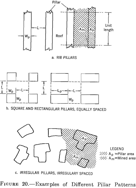
24 and 25. Therefore, the pillar width (or area) is determined for a given roof span (or mined area) and pillar strength. For example, consider the following cases: (1) Regularly spaced rib pillars, (2) regularly spaced rectangular pillars or square pillars, and (3) randomly spaced pillars with irregular shapes. Plans of these various systems of pillars are shown in figure 20, a, b, and c.
For rib pillars, case 1, where the roof and pillars are the same length, the ratio Am/Am + Ap can be replaced by L/(L+WP), and the design equation (see equations 43 and 45) is

For rectangular pillars, case 2, Ap in equation 44 is replaced by WpLp (where Lp is the length of the pillar) and
At = (L + Wp) (L + Lp)
where L = span between pillars in both directions.
Solving for Wp, (see fig. 20b)

where k = Lp/Wp the ratio of the pillar length to width,
For square pillars, k in equation 47 becomes
k = Lp/Wp = 1
For randomly spaced, irregularly shaped pillars, case 3, the ratio of the pillar area to the mined area can be computed and the size and shape of the pillar adjusted accordingly; the ratio (see equations 43 and 45) is

For first approximations from equations 46, 47, and 48, the compressive strength of the pillar, Cp, can be considered the same as the compressive strength of the rock, which had a height-to-diameter ratio of 1 as determined in the laboratory. If the height-to-width ratio of a pillar is less than 2 or greater than 0.5, the corrected compressive strength Cs is used, as given by equation 25, page 21. If the height-to-width ratio of a pillar is greater than 2 to 1, the compressive strength of the pillar should be determined from samples that have the same height-to-width ratio.
Illustrative Problem
As an example of pillar design, consider the following problem:
Depth of opening feet………………………………………………………….1, 000
Height of opening do………………………………………………………………30
Safe roof span do…………………………………………………………………….30
Average compressive strength of rock.p.s.i…………………………..—11, 500
Average weight-density of rock above opening lb./ft.³…………………144
From equation 18, page 21

and, for a safety factor of 4, the extraction ratio is
R = (11,500 – 4,000/11,500) = 0.65
From equation 46 the width of rib pillars is

For regularly spaced square pillars, the square pillar width from equation 47 is

For the rib pillar the height-to-width ratio of the pillar is about 2 to 1 and for the square pillar, about 1 to 1.5. Because the height-to-width ratio is not greater than 2 to 1, or less than 1 to 2, the corrected strength can be computed from equation 25, page 21. The corrected strength, for d/h=1/1.5, is Cs= —10,000 p.s.i. and, for d/h= 2, Cs= —14,000 p.s.i. Because the ratio of the corrected compressive strength, Cs, to the uncorrected strength, C1, is small compared with the safety factor of 4, the uncorrected compressive strength can be used with little error.
In Situ Stress-Strain and Physical-Property Measurement
Introduction
In the preceding chapters procedures have been described for designing single and multiple openings in competent rock. The basis for the design procedures was the same in all instances. With an assumed stress field and a rock strength determined from physical-property tests on specimens from drill-core or other rock exposures, the dimensions of the opening or openings and the extraction ratio were calculated that would result in the maximum stress in the pillars, roof, and walls of the openings being less than the rock strength. In setting up these design procedures it was necessary to make numerous simplifying assumptions that obviously affected the validity of design calculations. The error introduced by these assumptions can be determined, at least in part, by considering the results obtained from instrumented studies in underground workings and from laboratory investigations. In the following section, methods for measuring the stress and strain and the in situ strength of the rock are presented, together with the more pertinent results obtained.
Measurement of Stress and Strain
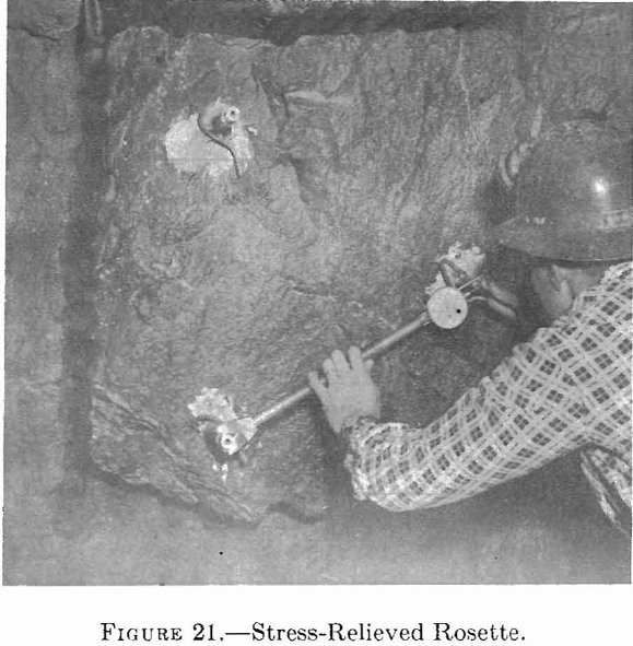
Several procedures have been developed for measuring the strain on the rock surface of an underground opening. Precision extensometers have been used to measure the change in strain between two fixed reference pins mounted on a rock surface. If distances are measured between the three pairs of pins at the corner of an isosceles triangle (rosette), the direction and change in the principle strain can be determined. Bonded and unbonded resistance-wire strain gages, vibrating-wire strain gages, and differential-transformer displacement gages have also been used for similar measurements.
If the rock on which the gage is mounted is cut free from the main rock mass, the stress, and hence the strain, in the gage rock will be reduced to zero. The difference in the strain reading before and after cutting the gage free is the strain resulting from the stress in the rock before relief. This “strain relief” procedure has been used for cutting out a gage with a diamond coring drill or cutting a large rock pillar free from a mine roof. A photograph of a strain-relieved three-pin rosette is shown in figure 21.
The surface stress can be computed from the measured strain, if Poisson’s ratio and the modulus of elasticity of the rock are known. These elastic constants can be determined from static or dynamic laboratory tests or from seismic measurements made in the field. However, the values of these constants, as determined by the different methods, are not in good agreement, particularly for sedimentary rock. A part of the lack of agreement is due to the anisotropic properties of the rock.
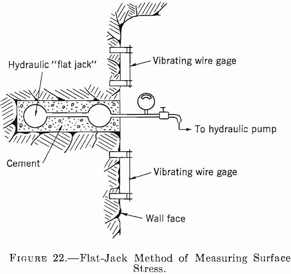
Mayer, Habib, and Marchant have developed a method for direct measurement of surface (or very near surface) stress. In this method one or more vibrating wire strain gages are mounted on a rock surface and an initial strain reading is taken. (See fig. 22.) A slot is then drilled near the gages to relieve the stress. A hydraulic flat jack is cemented into the slot, and the pressure in the jack is increased until the vibrating wire strain gages again give the initial reading. The rock stress is assumed to be the hydraulic pressure in the flat jack.
Stress or strain measurements made on the surface of rock openings have proved quite
erratic and usually give lower values than are predicted by theory—because of either geologic or blasting fractures in the rock or plasticity. The effects produced by rock fracture and/or plasticity can be better understood by considering the stress distribution in the rock as a function of the distance from the surface of an opening rather than on its surface. Chapter 3 gives the stress distribution around single openings of various shapes in an ideally elastic rock. It was found that the maximum tangential stress occurs on the surface for openings of all shapes and decreases rapidly with the distance from the opening. For a circular tunnel in plane strain where So=1/3Sv, the maximum stress concentration on the surface is 2.66 and at a distance of 1 diameter from the surface is 1.09.
Hast has developed a gage which can be inserted into a borehole and strain-relieved by drilling a concentric core around the gage hole
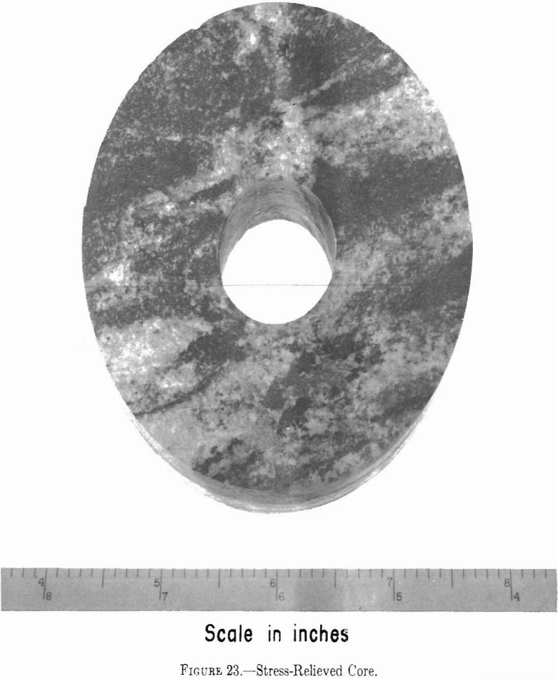
while the gage is in place. Figure 23 is a photograph of a section of core so obtained, The strain is given by the difference between the reading before and after the relief hole is drilled, as it is with surface gages. By making three strain measurements (for example, 120° apart), the direction and magnitude of the principal strain in the plane normal to the borehole can be calculated. From a laboratory calibration of samples of the mine rock under investigation, the direction and magnitude of the principal stress can be determined.
Using this procedure, Hast has found that the maximum tangential stress does not develop on the surface of the opening but several feet behind the surface, even in relatively hard, uniform rocks.
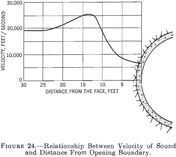
Another method of determining the effects of blasting and natural fractures in the rock near the surface of underground openings uses elastic wave-propagation velocity measurements made at various distances from the surface of the openings. The relation between the propagation velocity and the distance from the surface is shown in figure 24. The decrease in the propagation velocity near the surface, is presumed to result from fractures in the rock.
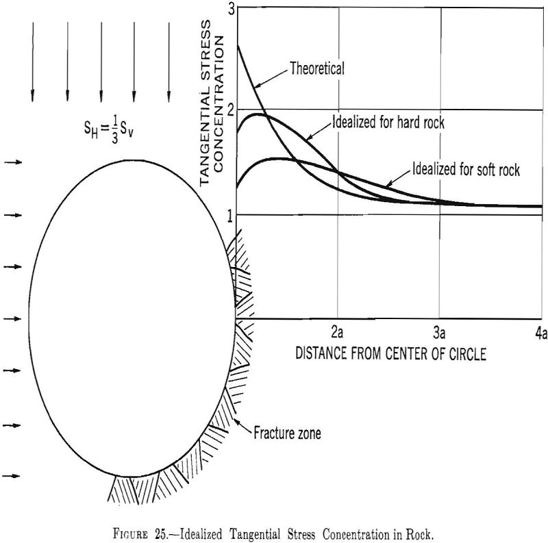
Based on the foregoing procedures an idealized measured tangential-stress distribution for a circular opening in a stress field where Sh=1/3Sv is shown in figure 25.
The fact that fracturing and/or plasticity lowers the stress on the surface of openings allows some reevaluation or modification of design procedures. If the maximum stress occurs several feet from the surface the effects of surface irregularities will be diminished. Hence, the assumption given in section 3.1 that the cross section of an opening can be represented by simple geometric shapes, such as circles, ellipses, ovaloids, and rectangles with rounded
corners, is consistent with underground conditions.
In the theory for stress distribution around a rectangle with rounded corners the stresses in the corners approach infinity as the radius of curvature approaches zero. If the rock either fractures or yields at a sharp corner, the maximum stress in the corner presumably develops in the rock along an arc with a radius such that the maximum stress is less than the rock strength. In the theory for a clamped beam or plate, the clamp is considered to be rigid and to form a sharp corner at the clamping point. Hence, the corner stresses should be infinite. In a mine the clamping rock probably would either fracture or yield under this stress, which would reduce the bending moment and stress in the roof layer at the clamping point. The results of an experimental-room study in a limestone mine indicate action of this type.
In sections 4.4 and 6.3 the average pillar stress for a room-and-pillar mine is given by

where:
Sp = average pillar stress,
Sp = vertical applied stress = —pgZ,
Am = mined area,
Ap = pillar area, and
At = Am + Ap = total area.
Figure 26 shows the relationship between the extraction ratio and the maximum and average pillar-stress concentration for ovaloidal shaped openings where Sh=0 and W0/H0 = 2.0. A similar relationship exists for other shaped openings. For an extraction ratio greater than 0.8 the difference between the maximum
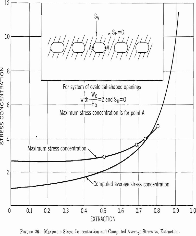
and the average pillar stress is small; for extractions under 0.8 the difference increases as the extraction decreases. For example, in a mine with ovaloidal shaped rooms having a width-to-height ratio of 2.0 and an extraction ratio of 0.5, the maximum and the computed average pillar-stress concentration is 3.0 and 2.0, respectively. However, if the surface stress is lowered by fracturing and plasticity, the difference between the average and maximum pillar-stress concentration would not be as great (probably in hard rock the maximum would be 2.5 and the average 2.0), and the pillar design and extraction ratio should be adjusted accordingly. This ratio would be further reduced if Sh is not zero.
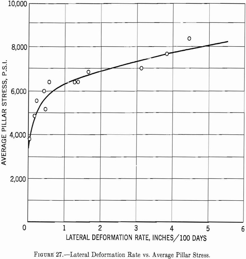
In the more plastic rocks the stress concentration on the surface of an opening almost completely disappears. Hofer has studied the deformation of pillars in 12 potash mines in Germany. These studies were made in mines that lie at depths ranging from 1,200 to 3,300 feet; the computed average stress (Sv) before mining was 1,000 to 3,000 p.s.i., and the computed average pillar stress (from equation 49) ranged from 4,000 to 8,200 p.s.i. The crushing strength of the potash as determined from laboratory measurements on cylinders 2 inches in diameter and 2 inches long was 4,000 to 6,000 p.s.i.—less in some instances than the pillar strength. For openings of the shape described in this report the maximum stress concentration is about 4. Hence, the maximum stress should range from 4,000 to 13,200 p.s.i.—in most instances considerably higher than the laboratory-determined strength of the potash. Two inferences can be made from these results: (1) The laboratory-determined crushing strength of the potash is lower than the pillar crushing strength and (2) the surface stress is relieved by plastic deformation. The second conclusion is substantiated by Hofer’s pillar-deformation measurements, which show that for an average pillar stress greater than 5,600 p.s.i. the pillars become relatively plastic. (See fig. 27.)
Measurement of Stress Field
Throughout this report it has been assumed that the stress field results from only the weight of the overlying rock, that is, that there are no tectonic stresses. For this condition the vertical stress, as indicated in chapter 3, is given by the equation
Sv = -pgZ………………………………………………………….(51)
and the horizontal stress by
Sh = MSv………………………………………………………(52)
In the absence of tectonic stresses the value of M depends upon the degree of lateral constraint and the value of Poisson’s ratio. If there is complete lateral constraint, then
M = γ/1 – γ……………………………………………………….(53)
M, the ratio of the horizontal to the vertical stress, can be determined by direct measurement, as will be described later in this section. However, some inference can be made regarding the magnitude of M from visual observation. For M= 0, that is, for no lateral constraint, the stress field is unidirectional and is given by equation 51. For this condition a tangential tensile stress will develop in the roof of a mine opening approximately equal to the value of Sv. As the tensile strength of most rocks is low (from 1/10 to 1/50 of the compressive strength), openings could only be mined at comparatively shallow depths without tension cracks developing in the roof. However, it has been observed in weak rock, such as salt or potash, that underground openings can be mined without failure of this type at depths greater than 3,000 feet. This fact would imply that the degree of constraint and the value of γ must be such that M is not zero but about equal to or greater than 1/3. For complete constraint and for γ=¼, the value of M is 1/3. If M is greater than 1/3, the tangential stress in the roof would be compressive and would reach a maximum value for the hydrostatic case, that is, for γ = ½. For rocks that exhibit plasticity this condition may be approximated.
If tectonic stresses are present some inference can be made regarding their magnitude and direction from visual observation. These inferences are based on the type of failure observed in and around underground openings. For example, rock bursts have been recorded at a depth of 1,800 feet in a strong granite syenite (crushing strength 40,000 p.s.i.). Even for an underground opening having an unfavorable shape the magnitude of the stress concentration should not be such that bursting would occur at this depth. It was found that in diamond drilling the wall rock in the same mine the core would break into thin wafers by an action that could only be attributed to a high internal stress in the rock. This stress could not be accounted for on the basis of a stress due to the depth of operation or the room geometry.
In tunneling operations in metamorphic rock, a violent failure of small areas, referred to as “spitting rock,” has been observed. In these instances a surface stress sufficient to cause rock failure could not be accounted for on the basis of the depth or shape of the tunnel. Bursting, spitting rock, and other indications of an abnormal stress field are unusual in sedimentary rocks.
Hast, using a borehole gage and strain relief drill described in section 7.1, has made stress measurements as much as 70 feet from an underground opening. This distance was large enough so that the measurement was not affected by the opening. Thus, the measurement gives the magnitude and direction of the stress field in the plane normal to the drill hole. By drilling in various directions and making measurements of this type it is possible to determine the resultant magnitude and direction of the three-directional stress field.
Employing this technique, Hast found that stresses of apparently tectonic origin are present even in a comparatively uniform rock (granite) and that the magnitude of the horizontal stress in some instances is greater than the magnitude of the vertical stress. No method has been developed for determining the stress field from observations in holes drilled from the surface. Hence, it is impossible at this time to determine the stress field and consequently the stress distribution around underground openings without first having access to underground areas. However, if the stress magnitude and distribution before mining can be measured, the procedures described in section 3.6 can be used to determine the stress distribution and concentration around an underground opening (in a two-dimensional, uniform stress field).
In Situ Measurement of Physical Properties of Rock
Greenwald, Howarth, and Hartman determined the in situ compressive strength of coal, using hydraulic jacks to load small mine pillars. More recently, Merrill has measured the in situ modulus of rupture of oil shale by successively widening an experimental room until roof failure was induced. Merrill also determined the in situ modulus of rupture of a limestone by pneumatically loading a large roof layer until failure was induced. Roof sag and strain measurements were also made on the layer, and from these measurements the elastic constants of the roof rock were determined. In both investigations the laboratory-determined modulus of rupture was in good agreement with the field value. However, the laboratory- and field-determined values of the modulus of elasticity did not agree. Although these experiments are informative the results are too meager to form generalizations about the relation between laboratory and in situ measurements, particularly as the rock in which these measurements were made was comparatively uniform. In areas where geological defects, such as fracturing, faulting, and bedding planes, destroy the isotropy of the rock, the in situ strength of the stronger rocks probably would be significantly less than that determined from small specimens in the laboratory. The instrumented. experimental-room investigation appears to offer a satisfactory means of making full-scale tests.
The theory of the stress distribution around single or multiple openings in massive rocks shows that the magnitude of the stress and the stress distribution are independent of the size of the opening or openings. This theory contradicts the experience of most mining engineers that a large opening is more subject to failure than a small opening. If the rock is not isotropic and homogeneous but contains geological defects (fractures, joints, bedding planes, and faults), the strength should diminish as the size of the opening increases because the probability of one of the defects occurring at a critical point increases with the size of the opening. Thus, it can be argued that a satisfactory in situ physical-property measurement can only be made at full scale. However, the influence of these geological defects may depend upon whether the rock is under tension or compression. For example, much of the total roof area of a flexing roof layer is under tension, and if defects occur in these areas their effect will be pronounced. On the other hand, the influence of geological defects in bedding planes normal to the axis of the pillar is small.
Data from Mine Surveys
One other means of checking the validity of design procedures is available, namely, calculating the stress in existing mine openings that are known to be stable and comparing the result with the strength of the mine rock. A survey was made of a number of “hard rock” open-stope mines in the Eastern United States in which the pillar size, pillar and room shape, and extraction were measured. In each mine particular attention was given to collecting data from the areas with the largest percentage extraction or with the maximum span. Rock samples were also taken by diamond drilling the sidewall pillars. Laboratory physical-property tests were made on specimens cut from these cores. About 20 mines were included in the survey. In all tests the calculated compressive stress in the mine pillars was less than the laboratory-determined compressive strength, and in most tests the pillar safety factor was greater than 4. Unfortunately, tensile-strength, comparisons could not be made because, as pointed out in section 7.2, the roof rock probably was not under significant tensile stress.
More limited data have been collected from “soft rock” mines, such as salt, potash, borax, and trona. The results show that the computed average pillar stress in these mines often is equal to the laboratory-determined crushing strength. In fact, incipient pillar failure generally is not indicated until the average pillar stress is greater than the crushing strength.
