Table of Contents
Ore grinding mills are really just slowly rotating barrels, but barrels that are growing in size so fast that the application of electric drives for them is rapidly approaching a technology like that for wind tunnels or pumped storage drives. This application is particularly worthy of care because some 40% of the 75 megawatts of power used by a large copper ore concentrator, or some 60% of the 200 megawatts supplied to a large iron ore concentrator, are for grinding.
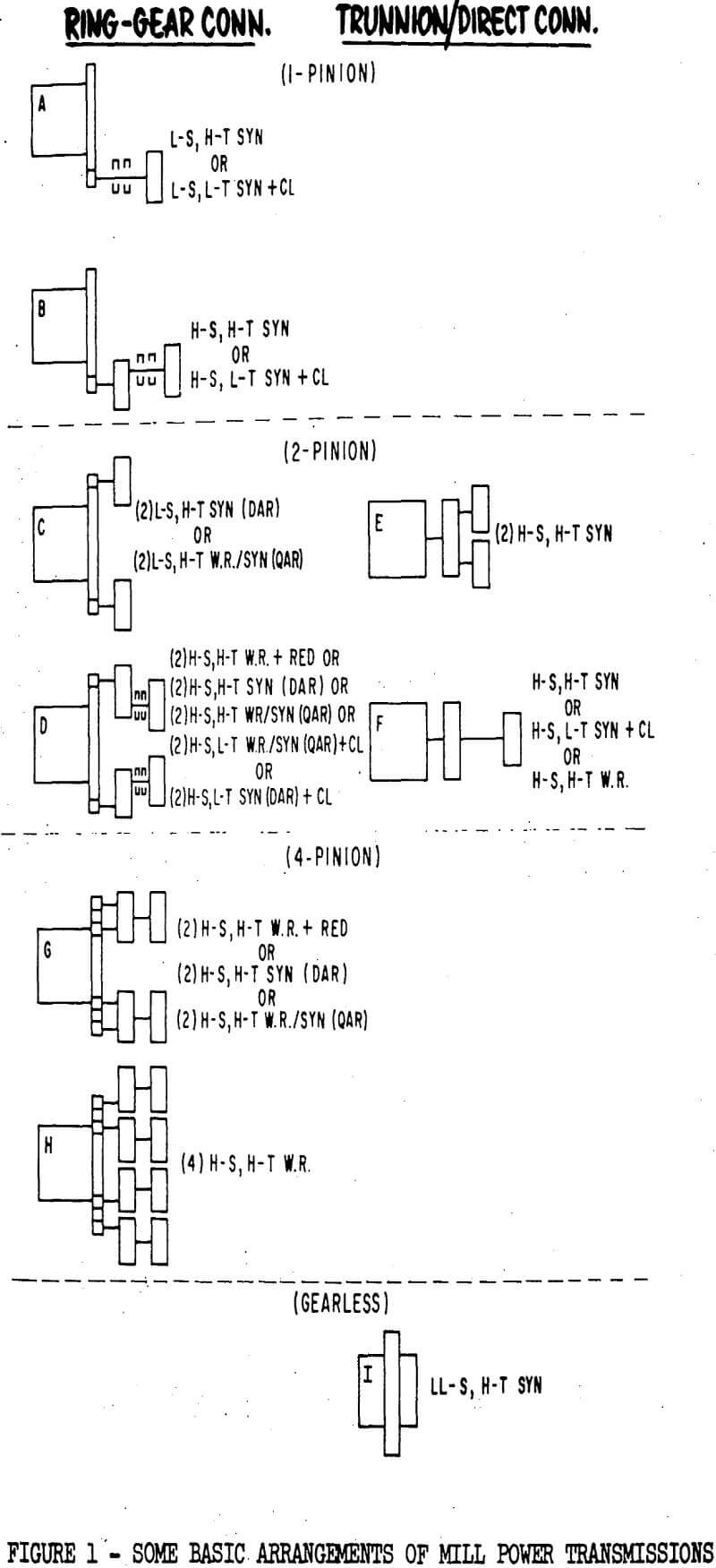
Mill Power Transmission Arrangements
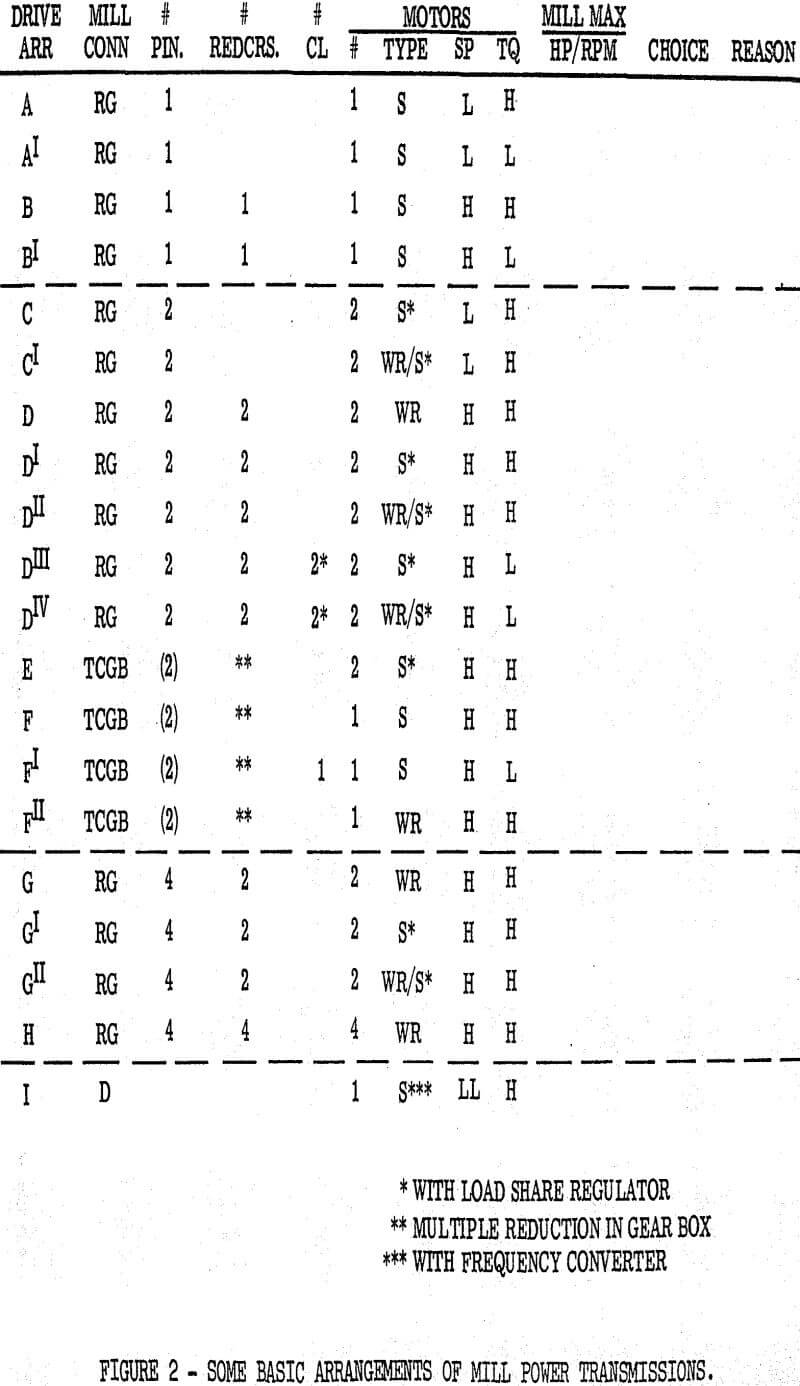
Arrangements (A), (B), (C), (D), (G) and (H) on the left are semi-enclosed-ring-gear connected to the mill at either the shell or trunnion diameter. (D) and (F) on the right are trunnion connected enclosed gear sets, (I) is gearless, direct connected to the mill shell or trunnion. There is a limit to the torque that can be transmitted from a pinion to a bull gear for long reliable tooth life, at reasonable cost, taking into account the high-torque burden on the drive and its rough grinding ambient.
The 1-pinion arrangement (A) can be powered by a low-speed, high-torque synchronous motor. There are thousands of these in use. An alternate is by a low-speed, low-(starting and pull-in) torque synchronous motor with a clutch added to accelerate the mill on the motor’s pull-out torque. There are scores of these in use.
Another 1-pinion arrangement (B) is powered through a speed reducer by a high-speed, high-torque synchronous motor for a reduction in first cost, and it can be used if efficiency is not paramount. There are several hundred of these in use. A clutch can also be added for softer start and some reduction in cost.
The 2-pinion arrangement (C) can be powered by two low-speed, high-torque synchronous motors, equipped with a direct-axis load-share regulator. Several of these are being considered today. Or, this arrangement is powered by two low-speed, high-torque synchronous motors with wound-rotor soft-starting windings and rheostats, and equipped with a quadrature-axis, load-share regulator for higher frequency response. Two of these at 9200 HP each are just being put into service.
Another 2-pinion arrangement (D) is powered through speed reducers by two high-speed, high-torque wound-rotor motors with soft-starting rheostats. Load-sharing is inherent with this type of motor. The speed reducers lower the first cost at the expense of efficiency. At this date there are eleven of these in use on this continent, one in Missouri, two in Ontario, two in Arizona, and six in British Columbis. Ten more have just been ordered.
The 2-pinion arrangements (E) and (F) are trunnion connected, enclosed gear sets to help protect the gearing against cement mill or other very adverse ambients if the fairly high gear premium may be-justified.
Arrangement (E) uses two high-speed, high-torque synchronous motors with a mechanical arrangement for initial, steady-state load sharing. Extra speed reduction is built into the gear set. There are some thirty in use, but there have been problems in maintaining load balance and in transient stability. They can be equipped with a direct-axis load-share regulator.
Requirements for Successful Mill Drive
The mill operating speed of a geared drive is usually fixed by a constant speed motor and must be preselected. That speed decreases as the mill diameter increases, thereby increasing the transmission and drive problem. Since speed has such an effect on grinding, production, mill wear, and resultant costs, it must sometimes be changed after installation by changing gears. At present, there is little interest in the mining industry in adjustable speed drives, but as process control strategies are further developed, and as mills in a plant become larger and fewer, the use of adjustable speed drives may emerge.
During starting, the mill charge action may be brought up through cascade to the equilibrium state of motion. Once running speed is reached, the ball or autogenous mill load torque smooths out, but the rod mill does not. Jackstrawing of worn rod pieces and other characteristics cause it-to continue surging.
While mill inertias are high at the mill, they are reasonably low referred to the drive motor(s) through the gearing. However, appreciable acceleration torque should be sustained during starting to minimize high-torque heating on the drive and to pass quickly through any resonant modes in this electro-mechanical system. An acceleration time of 8 – 12 seconds is normal, except for clutch drives, where 6-10 seconds is preferable.
The performance of a mill is predicted in advance from theory and from pilot plant experience with a particular ore. These conclusions are then scaled up and the mill drive sized. Two years and millions of capital dollars later, its true performance is observed. Its targets of production, grinding, power consumption or consumption of wearing parts may or may not have been met.
In multi-pinion drives, there is a requirement for equal sharing of total load by the drive parts. This means both steady-state and transient load sharing of both gears and motors in parallel. Mine hoist drive paralleling experience is not sufficient for calibration, since the larger mine hoist drives are essentially direct current, with armatures in series, or with special load sharing regulators. This load sharing requirement will be discussed specifically later under the heading “Risk Assessment”. At this point, though, the reliability of load sharing means should be predicted and torque and thermal margins should be added with this as a consideration.
Starting Effect on Mill Mechanical Parts
The control of net motor torque while starting the mill is built into the design of the high-torque, constant-frequency synchronous motor, with allowance made for the calculated loss of torque due to voltage dip.
The adjustable-frequency, high-torque synchronous motor would first be synchronized and then accelerated at controlled volts-per-cycle and regulated to constant acceleration. This is truly a soft-start. Note the absence of salient pole pulsations.
The high-torque wound-rotor motor starts the mill under control of a resistor-contactor secondary or a stepless liquid rheostat. The latter can be regulated for constant torque or constant acceleration, or some combination as indicated. The liquid-rheostat is preferable, but a little more expensive for smaller drives. Individual secondary rheostats are required, but pairs have matched servos.
Soft-start of a large mill drive is a must for either utility or self-generation source of power. At new ore locations, power system stiffness doesn’t seem to be growing as fast as large mill sizes. High starting current (usually of low power factor) drawn through the utility system,.plant transformers, and plant distribution networks causes voltage dips. A utility often limits that dip at the point of purchase to 3% or less. A dip at the motor in excess of 20% will cause excessive loss of starting torque and exposes plant contactors and relays to drop-out, loss of control sequence or instrument malfunction. The high reactive content must be generated by the utility and transmitted, with resultant transmission losses. This cost will appear in the power contract.
Initial Cost
These relative first costs have been estimated based on the following assumptions:
HP = 6000-8000/Mill
RPM =720 (HS), 180 (LS), 10 (Mill)
Torques = 200 – 140 – 200% (LR – PI -PO)
Motor voltage = 4000
Motor enclosure = Drip proof, guarded
Primary and secondary control included.
Soft-start optional.
In general, a motor voltage of 6600 is practical if that distribution level is required for other plant loads. But a motor voltage of 13,200 is considerably more expensive than 4000 (even including unit transformation between the two levels.)
Soft starting equipment has been shown optional for the following reasons. Synchronous (S) motors up to about 5000 KVA per mill can usually be started full-voltage across the line, depending on utility stiffness. Ore plants with mills larger than that and with two or more mills can profit by time sharing the capacitor starting equipment. The plant’s soft starting cost then would be $20/HP divided by the number of mills sharing the starter.
Load Sharing
Whenever more than one torque path exists between the driving motor(s) and the driven load, the designer needs to give special attention to assure proper division of load between the parallel torque paths. Motors are exposed to overload to the extent that one motor at a multiple-motor drive may be required to produce beyond its rating while other motors carry only a fraction of their rated load. Gears and couplings are designed to American Gear Manufacturers Association standards, which afford marginal continuous overload, plus greater momentary overload capacity for system dynamics such as load pulsations, drive starting torques, even an occasional mild abuse.
There are two principal areas of concern about gear load sharing which must be dealt with separately. The first concern is with average load balance between the separate halves of a dual torque path drive train. The second concern is with transient torques as a result of torque pulsations and electro-mechanical resonances both when starting and while running. This second concern will be dealt under “Risk Assessment.”
Design of the dual synchronous motor drives requires special attention to achieve satisfactory load balance between the two motors. Accurate positioning of the paralleled rotors during installation of the drive is essential (except for clutch versions) and must be maintained despite foundation movement, unequal mechanical wear, etc. Manual mechanical means of adjusting rotor angle have been used on dual synchronous drives, such as: rotor shift with respect to the shaft, gear type couplings with a differential modification, or stator rotation equipment.
Risk Assessment
Once a good mill design has been made, the designer must consider what could happen to make that design fail. A mill is not considered to have failed if it shuts down because of normal, protective devices or process sequencing but rather it will have failed if some part is thermally or mechanically overstressed such that it has to be repaired or replaced before operation at normal levels can be resumed.
Motor protective functions have been developed through experience to reduce exposure to failure from the following sources:
a) Voltage Quality – relays can sense poor voltage quality resulting from under (or perhaps over) voltage, reversed-phase-sequence, or phase voltage imbalance. Surge capacitors and lightning arrestors are commonly used to protect motor end-turns against lightning and switching surge overvoltages.
b) Frequency Quality – Although seldom a concern, underfrequency or overfrequency relays can be used to protect against line frequency changes. Harmonics of line frequency seldom cause problems in the motors.
c) Overload Protection – Phase overcurrent, thermal overload, and/or stator winding temperature detectors can be used to sense motor overload. The amortisseur winding of a synchronous motor can be protected during starting by a graduated squirrel-cage protective relay plus incomplete sequence shutdown. Temperature detectors can protect the external secondary resistors used with wound rotor motors from thermal overloads.
d) Fault Protection – Phase overcurrent, ground fault, and differential protection are commonly used measures for both synchronous and wound rotor drives. Wound rotor motors may, in addition, be provided with secondary flashover protection.
Evaluation and Selection
Each drive system is weighted from one (first choice) to ten (last choice) as viewed from each criterion. The first is easy. Only one is adjustable speed. Soft start mechanically can be appraised from the drive’s speed torque curve and the rate of application of torque to the parts. Starting voltage dip can be absolutely defined and its value calculated, as can running power factor and efficiency. These latter two are extremely important to operating cost and can be related to first cost in energy cost units over any planned period. Simplicity of installation is an opinion, based on number of parts, on types of parts, on necessary adjustments. Maintenance is part experience, based on life and failure, and part opinion, based on number of moving or wear parts and type of parts.
Reasonable first cost is definable for a known size and speed of mill and plant layout. Cost of space and foundation have been averaged by others, and installation can be estimated. Costs of parts are known. Weighting this criterion will naturally vary, but here is an estimate through the mill HP/RPM and hence,’ drive system spectrum. In this first cost comparison soft start was included for drives 6000 HP and larger that did not use a clutch or adjustable frequency. Either a 15 MVAR capacitor bank or a pair of wound rotor liquid rheostats was time-shared by three mills in a plant.