
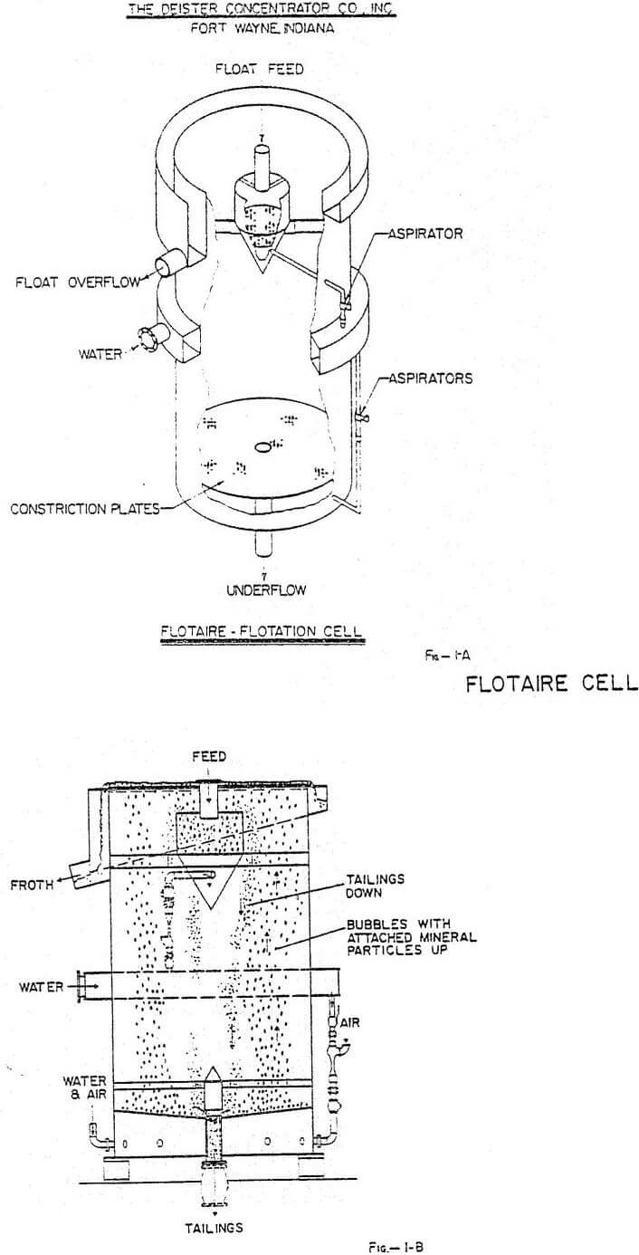
 The Flotaire Cell can be constructed in many configurations, but presently, we prefer a round tank that is 2 to 4 m in diameter with an overall depth of about 5 m. Simplicity of design, and operation, is a principle attraction of the Cell and can be best understood by reference to Figures 1A and 1B. Near the bottom of the tank, one or two constriction plates are installed. If two plates are used, the bottom plate will have relatively large holes, about 1.6 cm, and the top plate will have smaller holes, usually 0.6 cm or 0.8 cm in diameter. Water for fluidizing the pulp and air for aerating the pulp pass through the constriction plates. Water induced into the bottom of the cell aspirates air into the cell, thus eliminating the need for a blower. It can therefore be seen that the water conventionally used only for dilution is normally used for three purposes in the Flotaire Cell, i.e., (1) dilution, (2) fluidize pulp, and (3) aspirate air into cell.
Ore to be beneficiated is normally fed to the top of the cell through a feed distribution box. Water is introduced at the bottom of the cell below the perforated plates and the force caused by its velocity through the perforations keeps the solids (feed) in suspension.
The Flotaire Cell has the unique feature of being able to efficiently handle a much wider range of ore sizes than mechanical cells. For example, extremely fine ores, such as kaolin, can be beneficiated, and by simply changing method of operation, ores too coarse for conventional cells can be floated. In fact, this is one of the main advantages of the Flotaire Cell.
Normally, the Flotaire Cell will efficiently handle ores in which particle sizes are two or three meshes larger than can be treated in conventional cells. For example, in floating Florida phosphate, mechanical cells will float particles up to about 28 mesh, whereas, the Flotaire Cell will go up to about 14 mesh.
Flotaire System
The Flotaire System is a simple, efficient method of beneficiating ores, such as phosphate. It consists of the Flotaire flotation cell used in conjunction with a surfactant (or frother) that is compatible with flotation reagents used, the ore that is being treated, and plant water.
In floating phosphate, it is not unusual for BPL recovery to be increased more than 10%, the major increases being due to floating the coarse phosphate, up to 14 mesh, and more of the difficult to float phosphate, such as white phosphate, that is not normally recovered in conventional flotation cells.
Preferably, feed percent solids fed to the Flotaire cell ranges from 50 to 70% as most of the normal feed dilution water should be added beneath the constriction plates to fluidize pulp and aspirate air into the cell. Lower feed percent solids can be utilized, but this reduces capacity of cell.
Manifold water pressure is normally 30 to 40 psi, but system should be capable of operating between 25 and 45 psi. For some applications higher pressures have beer, used, but 45 psi is maximum for most applications. Recirculated water can be used provided trash larger than about ¼” is removed ahead of the eductors.
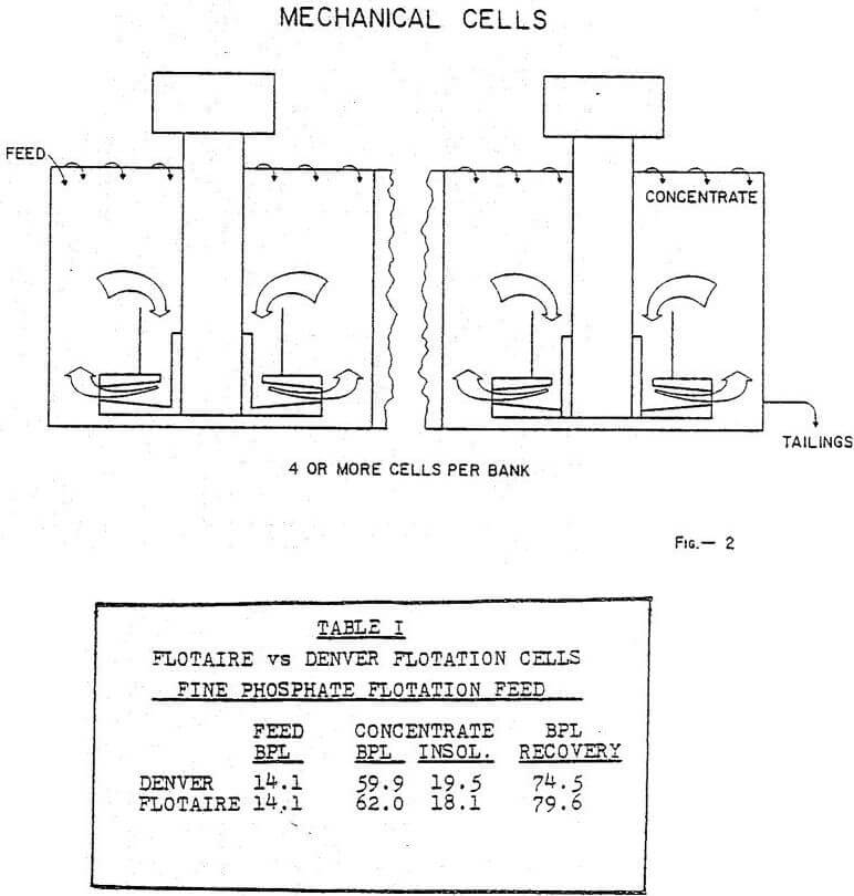
Conventional flotation cells usually operate on a pump or mixer principle as illustrated in Figure 2. That is, pulp is drawn into the bottom and pumped up and outward or vice versa, creating a strong circulating motion throughout the cell. Thus, the floatable particles are pumped to the bottom of the cell as well as to the top and to rise into the froth column they must escape from the relatively violent or strong pumping action. Contrasted with this is the Flotaire Cell in which fine air bubbles flow counter-current to the incoming pulp, thus fine bubbles are continually contacting and lifting the floatable material to the top and allowing the sink product to settle slowly to the bottom where it is discharged.
In most flotation cells, or banks of cells, feed is introduced at one end of a horizontal trough or tank and the non-float is discharged at the opposite end. The basic principle of the Flotaire Cell can be utilized in this manner and has been successful, however, we prefer to use the vertical flow principle in which feed is introduced into the upper half of the cell and the non-float discharge takes place at the bottom of the cell. On numerous occasions the “trough-type” cell has been compared with the deep vertical cell and, in every case, the latter proved best.
Most non-mechanical cells use air for transporting the pulp as well as for aeration. When this is done, it is difficult to maintain the desired bubble structure and power requirements are high. In the Flotaire cell, air is used only for aeration, not for the transfer of pulp, consequently, better bubble structure and distribution can be maintained. Plant operations have shown that metallurgy (grade and recovery) in large commercial size Flotaire cells is equal to or better than can be achieved in a mechanical laboratory batch flotation cell or a small Flotaire Pilot plant cell. Normally, this is not the case with other flotation cells.
The Flotaire flotation Cell has been found to be more efficient than conventional cells for floating phosphate, silica, copper, coal, vermiculite, mica, molybdenite, barite, kaolin and the same should apply to most other ores. One reason for increased efficiency for some ores is that the Flotaire Cell floats coarser ores, usually two or three meshes coarser than mechanical cells. A unique feature of the cell is that it can handle coarse ores and by adjusting mode of operation can handle extremely fine ores. The Flotaire Cell provides the mining industry with a tool for substantially increasing recovery of valuable minerals.
During the period discussed above more than 60 tests were conducted in an effort to determine optimum reagent dosages and air flow rates. Attempts to analyze the data in a logical manner failed because of the numerous variables and were confounded by the fact of the mechanical changes performed on the cell. An improvement or deterioration in performance could not be positively attributed to a change in parameters or mechanical changes. Analyses of frother and collector dosages vs. recovery yielded no meaningful correlation. Similar analyses of frother and collector dosages vs. froth concentrate ash also yielded no meaningful results.
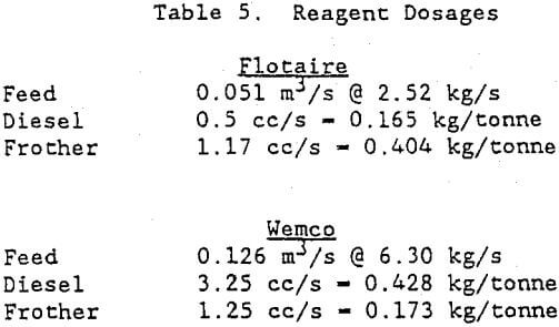
It is calculated that the Flotaire has a retention time of 555 seconds while that of the Wemco is 288 seconds. Experience has shown that the Flotaire does not use as much collector as the Wemco but does require more frother per kilogram of feed. Typical collector and frother dosages of the two cells are shown below in Table 5.
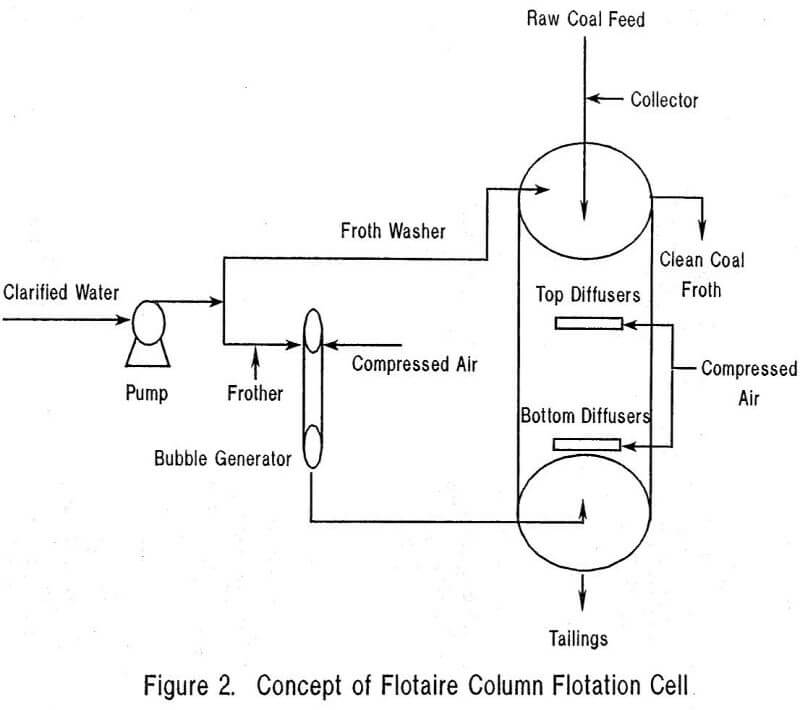
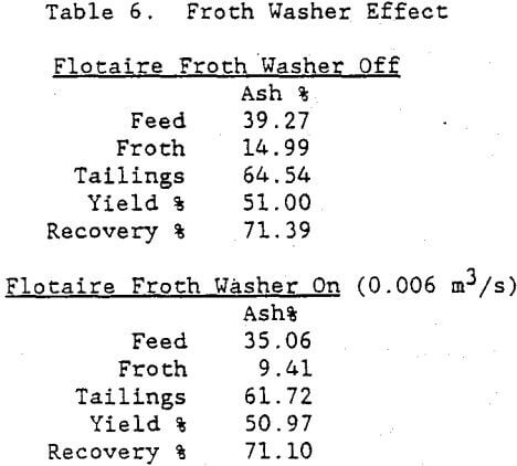
The two most important changes to the Flotaire cell were the addition of the new bubble generator, and bubble injectors. The others improved performance to some extent and were primarily implemented to cope with plant conditions. A froth washer may decrease the cell’s total retention time by adding water at the top of the cell but it is effective in lowering the froth product ash by more than 5 points with equivalent yield as demonstrated by the following test results in Table 6.
After a number of fits and starts the flotaire cell is operating effectively and plans are to improve its performance even more. The next plans for the cell are to relocate, the bubble generator nearer to the cell and install another- set of bubble generators to replace the set of top diffusers. Over the past two years many lessons were learned. Clarified water isn’t, feed lines clog, and oversize material finds its way into the operation. However, the basic design shows much promise and once perfected will find its place in the modern coal preparation plant.
 |
 |

|
 |