The possibility of increasing the efficiency of mineral processing plants by means of computer control has prompted metallurgists to examine their flowsheets more critically in order to develop practical control strategies. Control schemes in use to date generally rely on the automation of traditional and previously manually regulated control loops, for instance the addition of reagents to maintain a constant assay or a constant pH.
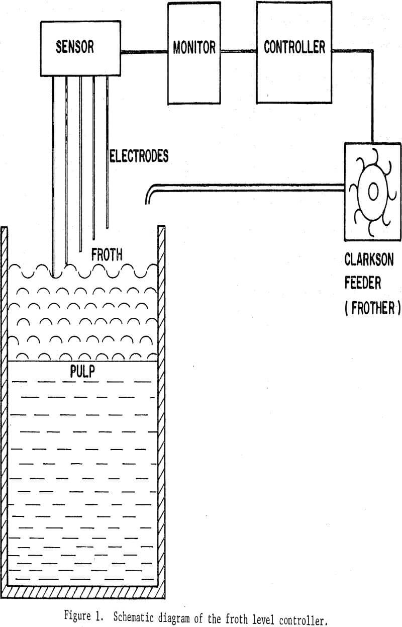
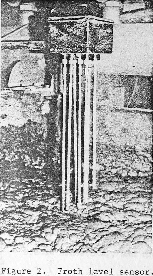
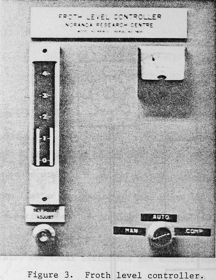
The froth level controller comprises (i) a sensor, consisting of a set of stainless steel electrodes connnected to a high-impedance, low-voltage electronic circuit which senses the number of electrodes in contact with the froth, (ii) a monitor which produces a 0-10 volt DC output as a function of froth level, and (iii) a controller which converts this voltage to a signal controlling frother delivery from a Clarkson feeder.
In this installation one froth level controller, installed in the second cell of one of the zinc roughers, operates in closed loop with a Clarkson feeder which delivers frother to the head of all the parallel banks. As indicated by the recorded froth level during periods with and without control, proportional action provides adequate stability and rapid recovery after an upset. Reset action would further improve control accuracy. The ease with which excellent, regulation has been achieved can be partly attributed to the relatively large frother flow rate (60 ml./min. average).
In addition to maintaining a steady froth bed, froth level control has helped in stabilizing the zinc rougher-cleaner circuit, especially when there is a variation in head grade or after rodding or a shut-down. Testing of frothers is also greatly simplified.
The pulp density meter is based on the principle, also used in the well-known bubbler tube, that the difference in hydrostatic head between two levels in a liquid or a slurry is directly proportional to the density. In the case of an ore pulp with a constant solids specific gravity, the differential head becomes a function of percent solids. In the present instrument, two 10-cm (4-in.) diam. stainless steel pneumatic pressure chambers fitted with rubber diaphragms and mounted vertically 15-30 cm (6-12 in.) apart at the lower end of a stainless steel pipe, transmit hydrostatic pressure through fine tubing to a differential pressure transducer located at the top of the pipe (Figures 7, 8).
There are a number of locations within a flotation circuit where continuous monitoring and/or control of pulp density would be beneficial. Development of a portable, direct-reading and easily installed pulp density meter has prompted the investigation of several applications.