Table of Contents
An in situ leaching geochemical simulator consisting of flow, mass transport, and graphics support programs has been developed. Two dimensional flow in heterogeneous porous media is modeled using a semi-analytic boundary integral technique. This method involves mapping streamlines to straight line segments in the complex potential plane. Leachant concentration and mineral values are modeled in this plane using the (one dimensional) potential coordinates. A fully implicit finite difference scheme is used to solve the resulting coupled system of four concentration equations. Graphical representations of streamline patterns, concentration histories, profiles and recovery curves are generated. An application of the model to uranium leaching in a heterogeneous aquifer and ore zone setting is presented.
ISL Hydrology Model
The ISL hydrology model uses a boundary integral element technique to describe the discontinuity in the discharge potential, ∅(x,y), that occurs along the boundary between zones of differing permeability. Although a direct analytic solution for ∅(x,y) is obtained everywhere in the flow domain, it cannot be inverted, so a Newton-Raphson technique is used to obtain (x,y) coordinate solutions which satisfy the stream function, ∅(x,y). ∅ and ψ are harmonic, conjugates.
The ISLGC model requires numerically solving a system of four one dimensional partial differential equations describing the change in uranium and oxygen concentration along each streamline as a result of convection, dispersion, and the chemical oxidation processes involved in leaching. Only longitudinal dispersion is simulated, transverse dispersion (across the streamline) is neglected. The ISLGC model can be used to simulate either a field or laboratory leach setting. Only the field simulation requires a prior ISL hydrology simulation.
The basic, one-dimensional, convection-dispersion equations with reaction terms are shown below along with the appropriate boundary conditions. Since ψ is constant along each streamline, the mass transport equations for each streamline reduce to a one dimensional flow problem with Φ as the variable representing position along the streamline. For notational convenience Φ is scaled between 0 and 1. At the injection well ∅ = 0 and at the recovery well ∅ = 1. The porosity is ∅.
A finite difference approximation is employed to transform these four equations into a system of nonlinear algebraic equations. These equations are solved simultaneously using a Newton-Raphson iterative scheme. A successive-overrelaxation method (SOR) is used to solve the banded matrix (9 bands) resulting from the finite difference approximation.
The Newton Raphson Procedure
The computational problem can be expressed as follows. Find a vector xs, xs = (X1 Xn)T such that F(XS) = 0 where n is 4 times the number of nodes on the streamline, T denotes transpose and F(X) = (F1(X) Fn(X))T is the nonlinear operator resulting from the finite difference approximation. Note that F(X) is an n-vector, not a scalar. That is, F(X) = 0 is the system of nonlinear algebraic equations generated by the finite difference approximation for which a numerical solution, X, must be computed.
The N-R method used in ISLGC is a standard extension of the method used in one variable. An initial guess for Xs is made, say X0. Then F(X0) and the linear approximation to F near X0, DF(X0) is the Jacobian of F, evaluated at X0 i.e.
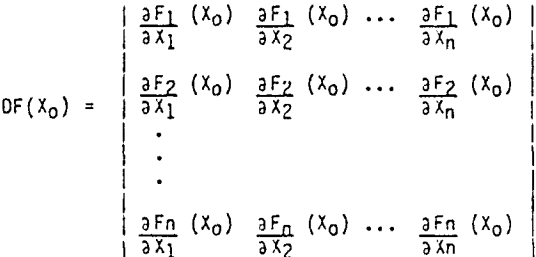
The next approximation to Xs, X1, is then obtained by solving the linear system DF(X0).(Xo-X1) = F(X0) for X1. In ISLGC, this is done by computing the solution (vector) ΔX of DF(X0) · ΔX = -F(X0) and then setting X1 = X0 + ΔX. The succeeding approximation, X2, is obtained in the same fashion.
An Application of ISL and ISLGC Models
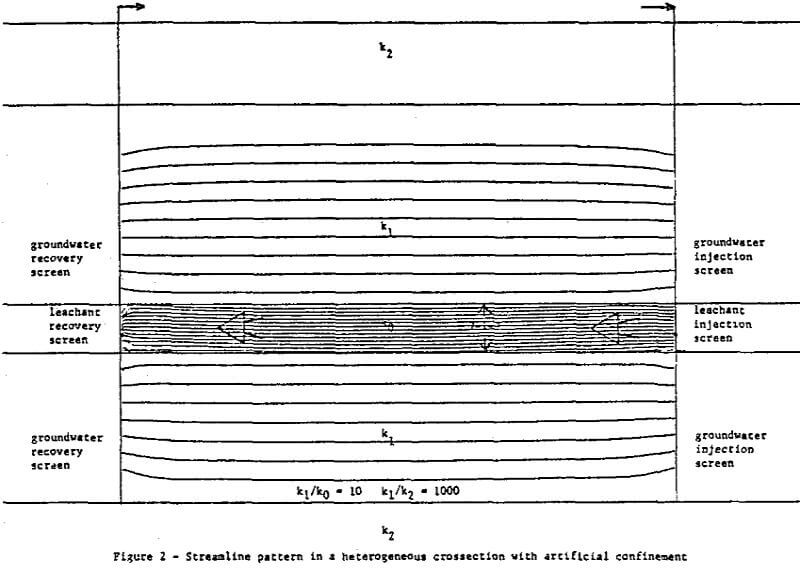
The effect of contrasting zones of permeability on leachant flow at the Hobson site can be simulated in two dimensions with the ISL hydrology model.
In light of the post leach core analysis, (which indicated the mineralized zone was highly cemented) the 10 to 1 difference in permeability between layers k1 and k0 used in this simulation is probably a conservative estimate of the actual permeability difference that exists at the Hobson site. If the zone of high grade mineralization is also the low permeability zone, ko, in figure 1, then it is apparent that mineral-leachant contact is reduced to an area within aim radius of the injection and recovery screens.
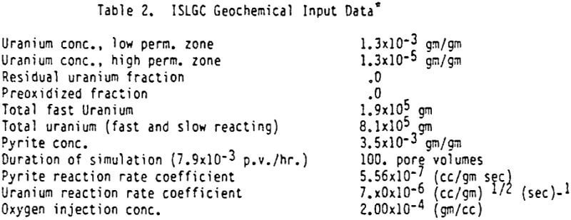
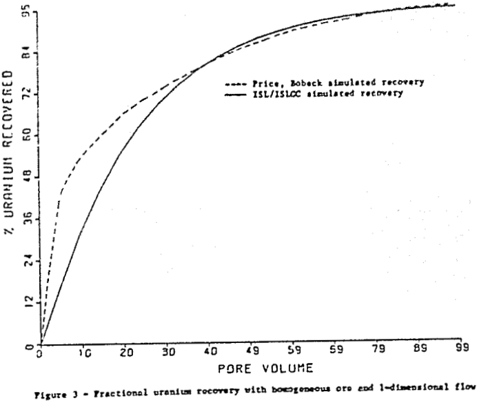
The condition of induced one dimensional flow is a close approximation of the conditions simulated by Guilinger in laboratory leaching experiments using samples of the Hobson ore material. Using the streamline pattern from this simulation as input to ISLGC. The approximation is limited by the fact that the ISLGC model permits only a single uranium reaction rate. Only fast reacting uranium not bound with organics is considered in this simulation.
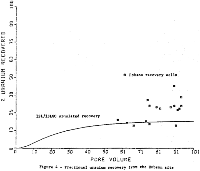
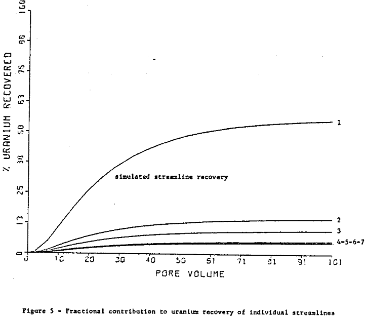
If hydrology data for the streamline pattern of figure I is used in ISLGC, instead of that for figure 2, (reaction rate parameters remain the same however) a simulation of the Hobson site is obtained that closely approximates the low uranium recovery rate observed in the field.
Further, the case study is a relevant illustration of the ISL and ISLGC models’ capabilities for predicting the effects of two dimensional heterogeneities in permeability and mineralization on in situ uranium recovery. It also illustrates the importance of geochemical modeling tools to well field design.

