Table of Contents
The high tension belt conveyor is introducing a new and tremendously expanded era of low cost bulk material handling. High tension belt conveyors are generally those installations involving very long centers, high lifts, or drops, in which the belts are stressed up to their maximum tension values, and further, where the belt construction provides tension capacity far beyond what is possible with conventional belt constructions. With these high tension installations, the magnitude of the forces involved demands careful refinement of accepted design practice in order to achieve optimum balance of all factors.
General Belt Capacity Considerations

The belt conveyor capacity tables published by various belting and conveyor equipment manufacturers vary to a considerable degree, and the ratings given are quite conservative. Of necessity, these published ratings are based on the handling of average materials under average conditions.
In applying a high tension belt, all possible capacity from the belt must be obtained in order to hold its width to a minimum and thereby limit the initial cost. Two factors are involved, loading to maximum cross section area and traveling at a maximum practical speed.
Belt Loading: Proper treatment of the loading of the belt will result in maximum cross section to the load, and published capacity ratings can be exceeded, sometimes by appreciable margins. On the 10-mile conveyor haul used in the construction of Shasta Dam, California, although the rated capacity of the belt line was 1100 tons per hr, at times the system handled peak loads of 1400 tons per hr, almost 25 pct better than the rated capacity. One of the large coal companies has been able to exceed rated capacity by as much as 50 pct.
Belt Speed: High belt speeds should be used in high tension work. Obviously, high belt speeds enable haulage on a narrower belt, reducing initial cost.
The time cycle of a belt can be defined either as the length of time required for any given point of the belt to travel completely around the conveyor, or the number of times per unit of time a given spot on the belt passes under the loading point. Dividing the total length of the belt by the belt speed, or roughly, twice the conveyor centers by the belt speed, gives the time cycle. For example, a conveyor of 1000-ft centers and 500-fpm belt speed would have a time cycle of approximately 4 min.
Selecting the High Tension Belt
The selection of any conveyor belt results from proper balance of strength and quality factors. The high tension belt requires a far more thorough analysis of the strength factors and their determinations than has been necessary for the conventional installation. But as to the quality factors, mainly the covers and rubber used, the application of the high tension belt does not involve any new considerations other than possibly the effect of the loading point time cycle on cover thickness.
Complete analysis of the strength factors involves the calculation and analysis of the belt tensions, with particular emphasis upon the evaluation of horse¬power determination formulas, the treatment of slope, and acceleration tensions. The steps involved in determining the tensions for the high tension belt application are the same as for any conventional belt except that all steps must be completely analyzed, particularly for the effect on the total tension. These steps are essentially the following: (1) Horsepower determination, (2) maximum belt tension determination including: (a) effective or working tension, (b) slack side or initial or drive friction tension, (c) slope or weight of belt tension, (d) breakaway or starting tension, (e) acceleration tension.
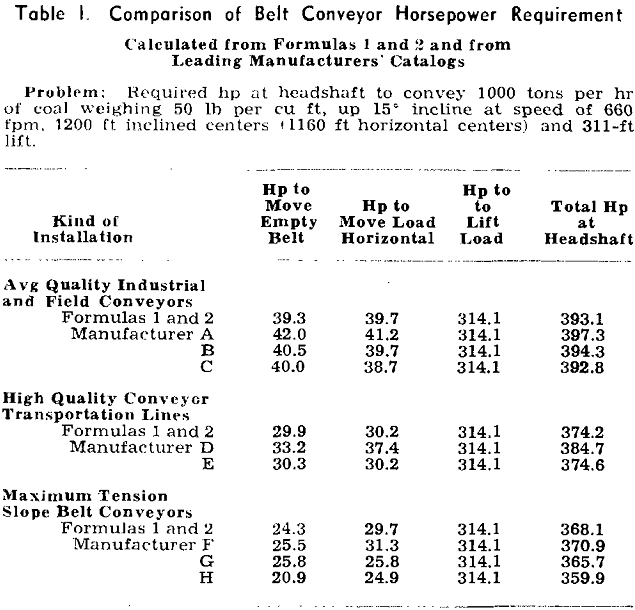
Horsepower Determination: In the published literature on belt conveyor design, there is agreement in the calculating of the various tensions after the horsepower has been determined, but there is a confusing variety of methods of horsepower determination, with equally confusing results. Inasmuch as high tension applications use substantial amounts of power, it is highly important that the horsepower determination be accurate, and a study of this factor is particularly pertinent.
Comprehensive studies of friction losses, notably on the 10-mile Shasta line and on one of the earlier long distance coal handling installations, have demonstrated that the 0.03 factor is unnecessarily conservative when all elements of the conveyor design and construction are well carried out. The scatter-band of the readings from Shasta showed that 0.022 was never exceeded.
For average quality installations, industrial and field conveyors,
C = 0.03 Lo = 150
For high quality installations, conveyor transportation lines,

For maximum tension installations, slope belt conveyors,
C = 0.015 C’ = 0.022 e = 0.007 h = 0.004

where C = idler friction factor
C’ = idler friction factor
Q = weight of moving parts, lb

S = speed of belt, ft per min
L = horizontal centers, ft
Lo = centers correction, ft
T = tons per hr, 2000 lb
H = lift or drop, ft
e = correction factor for added hp, empty belt
h = correction factor for added hp, moving load horizontally
Centers Correction Factor: The power consumed by the belt in going around the terminal pulleys must also be considered. This factor is largely independent of the conveyor centers and its early treatment, while satisfactory for the average length conveyor, overpowered the long center conveyor. Many handbooks of 20 years ago determined terminal friction losses by arbitrarily increasing the power for moving the empty belt and for horizontal conveying by 20 pct for conveyors up to 50 ft in length, 15 pct for 50 to 100 ft, 10 pct for 100 to 150 ft, and 5 pct for conveyors over 150 ft centers.

Beyond the treatment of the friction factors, there is little need for further discussion of these formulas, for there are no other differences. It must be emphasized again that the peculiar requirement of the high tension belt is a matter of degree only. The magnitude of the forces involved seriously enlarges what are normally insignificant differences and every possible refinement is necessary to a final balanced design.
Slope Tension: The slope tension found on all inclined or declined units is the weight of the belt hanging from the head pulley, minus the friction of the idler equipment. With slope belts of long inclined centers, the weight of the belt hanging from the head pulley imposes a considerable amount of tension, and it is a factor that must be considered. At the same time, this slope tension must be put to work for it frequently will supply all or most of the necessary slack side or drive friction tension, even for large horsepowers. When it is possible to locate a horizontal gravity type of takeup at the tail end of a slope conveyor, this means that the weight of the belt is supplying practically all of the counterweight tension that otherwise would have to be added.

It is important therefore that the magnitude of the acceleration forces be accurately determined. It can be shown that the acceleration tension in a belt for horizontal and inclined conveyors varies directly with the belt speed, and inversely with the friction factor used, the type of drive employed, and the time of acceleration. It can further be shown that the acceleration time in seconds will vary within a range of roughly 1/5 to 1/30 of the belt speed in feet per minute. When acceleration tension is held to a breakaway tension of 135 pct, the acceleration time may be obtained quickly and fairly accurately by letting acceleration time in seconds equal 5 pct of the belt speed in feet per minute.
Belt Specifications
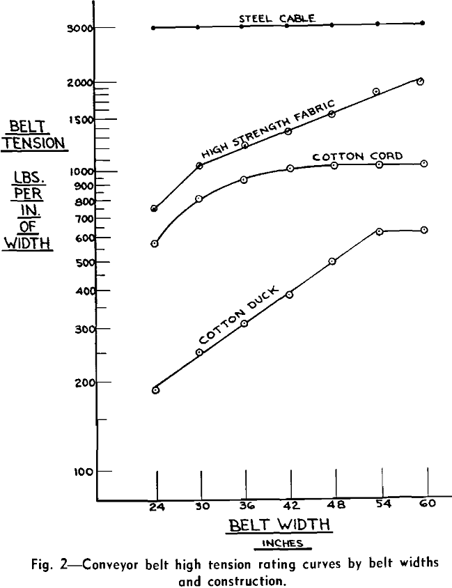
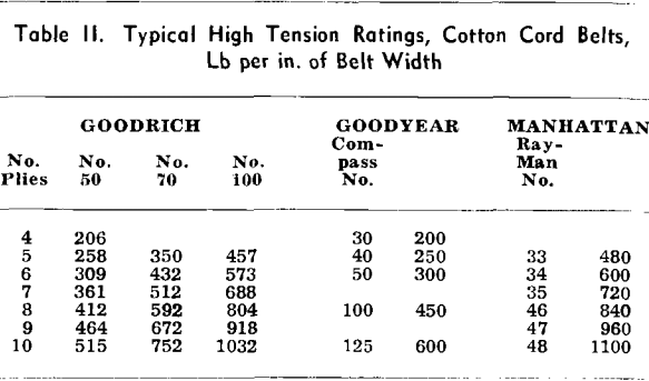
With the determination of the maximum tension requirements, the type of belt can be selected. In recent years, great strides have been made by the belting manufacturers in increasing the tension capacity of conveyor belts. This development has been along several lines, the more common being the use of cotton cord constructions, high strength fabric construction, and steel cable construction.
No one construction is best for all conditions. A complete study of all the factors is necessary each time, and great variation in the final selection can be expected. For example, with a slope belt problem, although the belting cost might be very much lower if two or three flights are used, this saving in belt cost might easily be outweighed by the cost of providing the necessary machinery rooms underground, plus the cost of drifting a large enough slope to get the heavy drive machinery down to the machinery rooms. In such an instance the use of a very high tension capacity belt, such as a steel cable belt, even though high in initial cost, could easily be the best and most economical selection.
Along with tension capacity, another important point in belt selection is that of troughability. A conveyor belt must be sufficiently flexible laterally so as to trough properly upon the supporting idlers. This is important both from the standpoint of obtaining the proper load-carrying capacity, and for proper training of the belt to run true both empty and loaded. At the same time, however, a belt cannot be overly flexible because it must also adequately support the load it carries; that is, there must not be excessive sag of the load, or dropping of the belt edges between idlers, or creasing of the belt in the gap between idler rolls. With high tension problems, however, because of these tensions, the ability of the belt to support its load is seldom a factor in the belt selection.
It must be emphasized that the high tension ratings for conveyor belts that are shown cannot be used indiscriminately but can only be used when every factor of conveyor design is given highest possible quality selection. That means approval from the engineering department of the supplier on the engineering of the conveyor, on the starting controls, and the braking. Vulcanized splices are essential, and pulley sizes must be larger by at least one ply than the handbook recommendation. All of the equipment must be top quality and excellent maintenance must be provided. The belts must use top quality skim coats, and provision must be made for vulcanized repairs. Counterweighted takeups must be provided with ample provision for resplicing the belt. The installation must not be overmotored.
Idler Selection
The second major item of cost in any high tension or long center belt conveyor application is that of the belt idlers. Ever since the firm establishment of the antifriction bearing type of belt idler, standard idler equipment has been fully equal to the demands of virtually every conveying condition. A wide range of good idler equipment is available today, and for high tension applications, it is only the high grade type of antifriction bearing idler that can be considered. Although all high grade idlers can be used for high tension belt conveyor work, there are some factors that must be considered.
A good seal is required to protect the bearings in applying idlers to high tension work. All high grade idlers have more than ample bearing capacity, and it is highly important that the bearings be kept protected so as to maintain this bearing capacity. For that reason the bearing seal must keep out grit and dirt effectively under all operating conditions. At the same time it must have a long life and not require periodic replacement.
A second important idler selection factor is the necessity of rugged roll construction. In order to have a rugged roll, the wall thickness must be adequate, and construction of the roll must be as a unit. There must be permanent connection of the shell to the ends and of the ends to the bearing tube or roll shaft. No joints should be present to loosen from impact and corrosion. The supporting brackets and the base on which they are mounted must be strong and rugged. If a strong roll construction is not adequately supported, the value of the roll design is largely lost.
The selection of idlers for belt conveyors has always been a matter of experience rather than any clearly defined rules. One manufacturer made a step forward in simplifying idler selection by applying service factors to the operating conditions in order to determine whether the commercial grade ball bearing idlers should be used or the precision grade, antifriction bearing idlers.
In high tension work it is particularly important that the change in contour of the belt in going from the troughed position on the idlers to the flat position over the head pulley must be done gradually over a considerable distance to keep the stresses in the belt edge from becoming excessive. The normal practice of not supporting the belt between the first idler and the head pulley is impractical because of the unusually long distance. Instead, a gradual change in belt contour is accomplished by means of special transition idlers in which the length of the center roll is gradually increased.
Drives
The tremendously expanded horsepower capacity of the modern, high tension belt now makes drives of hundreds of horsepower a commonplace for belt conveyors, and the record to date is chalked up by an installation now being made which will use a 1500 hp motor. The selection and application of such large horsepower drives for belt conveyors calls for careful study.
Pulley Drives: The drive arrangement for high tension belts is very often made simple by taking full advantage of the high tension capacity of the belt and using a simple snubbed pulley drive arrangement at the head pulley. Applying all of the horsepower to a single snubbed pulley is much preferred to using a dual pulley or tandem drive, which introduces problems of its own. Fig. 11 shows the belt tensions when using a snubbed pulley drive and a dual pulley drive for the same problem. In this case, while the snubbed pulley drive arrangement does impose 12,000 lb additional belt tension, the maximum still falls within the working limits of the belt that would need to be used anyway. The 1140 lb per in. tension in the dual pulley arrangement would require the use of a 1400 lb or 1500 lb per in. steel cable belt, and the 1380 lb tension for the snubbed pulley arrangement still falls within the limits of that belt. This example is by way of illustration only since in the actual determination of the maximum belt tensions for the final selection of the belt, other considerations enter in. Even if a stronger belt must be used, the additional cost of the belt will usually be less than the added cost of the dual pulley drive arrangement.
Direct Connected Speed Reducer Reductions: While it is entirely possible to use a secondary drive reduction such as a chain drive between the speed reducer unit and the drive shaft, generally it is more practical to couple the slow speed shaft of the speed reducer directly to the pulley drive shaft. The amount of detailed study and consideration that must be given to the high tension belt installation very closely determines the final belt speed, and any future variation in speed is unlikely. The fixed ratio of the speed reducer is not a handicap. Moreover, because of the high horsepower and the relatively slow speed, any secondary drive reduction must be massive in size and often the necessary space is not available. It is important to have the drive reduction as compact as possible, completely enclosed, and operating in oil.
In the large horsepower and the large reduction sizes, the range of selection of standard speed reducers now available is rather narrow with big jumps between sizes. It is therefore frequently necessary to select a reducer unit that is larger in capacity and of higher initial cost in order to obtain one of sufficient capacity.

In laying out transportation by means of belt conveyor systems, an auxiliary drive can be used at the tail end of individual conveyors in order to convert more of the tension capacity of the belt into working tension. The net effect is to make longer centers possible, with the use of fewer units and therefore a reduction in the number of transfer points. Locating a drive pulley at the tail is simply widely separating a dual pulley drive, moving the secondary pulley to the tail. Doing this eliminates some of the inherent disadvantages of the dual arrangement.
Motors and Controls: The proper selection of the motors and controls is a problem for the electric equipment manufacturers to solve. Several considerations must be called to the attention of the electrical equipment supplier. Because of close control of the starting torque and the balancing of motor speeds, the wound rotor type of motor is a must, and where dual and multiple motors are involved, they must be carefully matched. On declined units, the winding must be suitable for generation of power by the motor, which thus serves as a brake to govern speed and prevent runaway. Generally it will be more economical to use low-speed motors instead of using larger reductions through the speed reducer units.
Declined conveyors introduce problems of their own, inasmuch as there is no holding against reversal of rotation and runback, which immediately rules out the use of any ratchet and pawl or roller holdbacks, and requires the use of some form of band brake arrangement. For declined conveyors, a very generous oversize rating selection with adequate provision for heat dissipation is a must.y

