Table of Contents
Mining companies have been confronted with a multitude of production problems in their endeavors to extract maximum quantities of ore at minimal costs. These problems are further compounded by the harsh mining conditions of deep vein operations, such as those found in the Coeur d’ Alene mining district of Idaho. One of the major obstacles has been that of ground control, where increased artificial supports are required for maximum recovery of the sill pillars. At the same time, greater emphasis must be placed on minimizing the exposure of mine personnel to the hazards of rock bursts caused by stress concentrations in pillar areas. In recent years, hydraulic backfill has been one of the principal methods used for ground control in many deep vein mines.
The Bureau of Mines has been involved in a continuing research program to study hydraulic backfill and its supports potential since 1961. Results of some of this research have included the determination of the physical properties of backfill, how these properties vary with the use of chemical additives and compaction methods, the influence of various factors on water percolation rates, and field measurements of stope wall deformations and pressures within the fill. Other related research includes rock mechanics studies at several mines in the Coeur d’Alene district.
Despite the information gained from this and other related research, there is still no method of determining the quality of backfill required for a particular ground-support situation. As a result of this deficiency, selection of backfill has been based primarily on trial and error and past experience. The objective of this research is to present the results of preliminary numerical analyses on the support performance of various qualities of hydraulic backfill with an ultimate goal of providing mining management with an analytical tool to assist in making decisions concerning ground control and employee safety.
Numerical analyses have been used in previous research projects. Stope behavior studies were made by Blake using the finite-element method of analysis. These studies were based on the assumption that rock masses undergo purely elastic deformations, then fail suddenly. More recently, Pariseau and Kealy presented results of a preliminary study of a single stope using the finite-element method with an elastic-plastic analysis based on the Mohr-Coulomb yield criteria. This research is an expansion of the latter report, in which, a modified version of the same program was used to analyse two vertically adjacent stopes separated by a sill pillar.
Computer Program
The numerical analysis used in this research was a computer program developed by Dahl, which was based on the finite-element method. Basic assumptions of the program include two-dimensional plane strain, and elastic analysis with isotropic materials. Options include anisotropic materials and elastic-plastic analysis utilizing either the Mohr-Coulomb or extended Von Mises yield criteria. Details of the theory, limitations, and use of the program may be found in the references.
Prior to its use in this research, the program was modified by Bureau of Mines personnel to optimize computer run time and to incorporate options for computer plotting of pertinent output data.
The program has provisions for incremental analyses such that a complete stoping operation may be represented as a series of individual cut-and-fill steps. The program is independent of time; therefore, each cut is assumed removed at one time and each fill placed in a single lift. Using stresses from the previous step as initial stresses, incremental displacements and stresses for each cut or fill are determined and accumulated as total stresses for use in the next step. Output results are provided for each step so that the complete history of the mining operation may be traced.
Use of the program initially requires a mathematical model of the study area. Basic input data includes the geometry of the model; the boundary conditions imposed; and the physical properties of the materials involved. Out-put data includes deformations, normal and shear stresses, principal stresses, principal strains, and areas of failure.
Finite-Element Stope Model
The first step required in the finite-element analysis was the preparation of a mathematical model of the cut-and-fill stoping operation. In this study, no attempt was made to duplicate a working stope, but the model was generally based on a particular area of one mine in the Coeur d’Alene mining district where field measurements had been gathered.
The area modeled consisted of a rock mass 1,060 feet high by 1,190 feet wide, the top of which was located 5,190 feet below the ground surface. The rock mass was assumed bisected by a vertically dipping vein 10 feet wide, which extended from the surface to an infinite depth. A vertical line of symmetry through the center of the vein permitted modeling of only one half the rock mass (fig. 1)
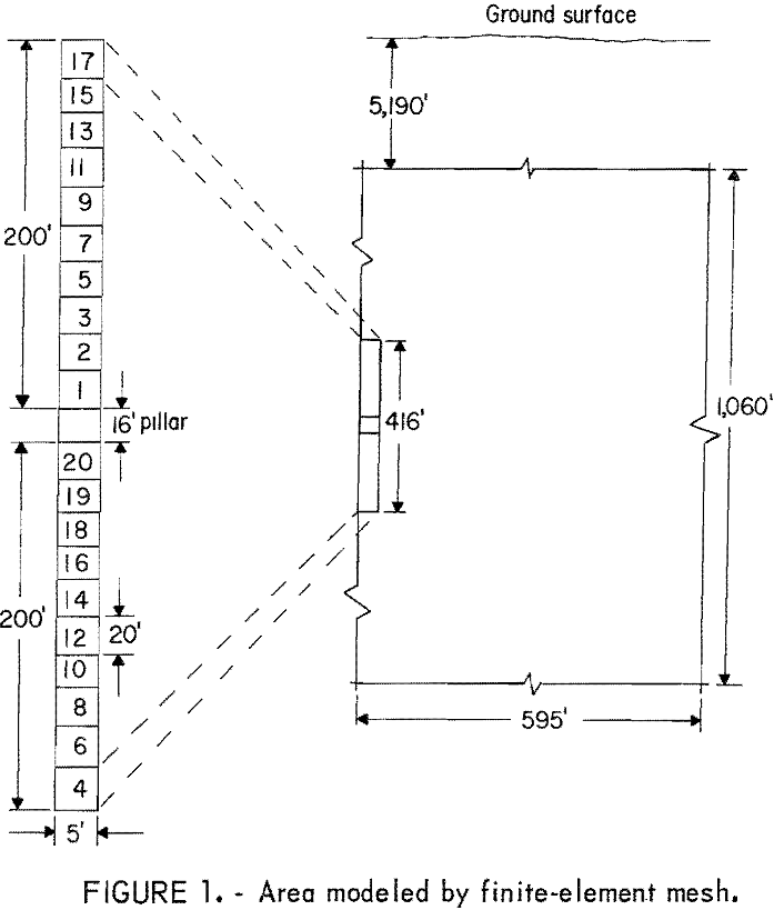
The specific area of interest was that portion of the vein located between 5,512 and 5,928 feet below the surface. This area was divided into two 200-foot stopes separated by a 16-foot sill pillar. As shown in the blow-up of figure 1, each stope was divided into 10 segments, which represented the lifts to be cut and filled. The numbers shown on these segments indicate the mining sequence used.
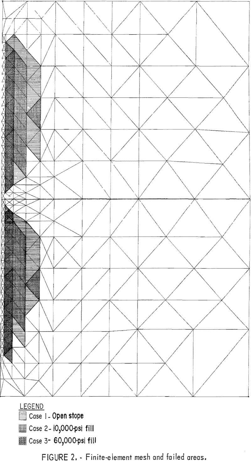
The rock mass was then idealized as a two-dimensional mesh of triangular finite elements interconnected at the apexes by modal points. The size and density of the elements were based on the degree of resolution required. The most critical area has the smallest sized elements and greatest density of elements. Proceeding away from the critical area, the size of the elements increases and the density of the elements decreases until the boundaries are reached. The boundaries are imposed at a point where the fixed boundary conditions have no appreciable effect on the information required within the critical areas. A portion of the mesh in the vicinity of the pillar is shown in figure 2.
The fixed boundary conditions imposed were zero displacements normal to the outer boundaries of the model (fig. 1). Displacements normal to the vertical axis of symmetry were also set to zero. The initial state of stress was assumed to be a gravity-loaded rock medium under complete lateral restraint. This assumption is approximately intermediate to uniaxial and hydrostatic cases. The state of stress in the rock and old backfill varied as the stoping operation progressed. Gravity stresses were used as initial stresses in succeeding steps, and the weight of the newly placed fill was applied as body forces. However, the exact state of the initial stress field need not be known for comparing the relative performance of different quality fill.
Rock Properties
The presence of faults, joints, and other geological factors tend to make rock masses weaker than laboratory testing of that material would indicate. Consequently, to simulate in-situ conditions for computer analysis the laboratory-determined material properties must be reduced. A method has been developed to determine a reduction factor that is applied to the elastic and strength moduli of the rock mass. It involves a series of computer analyses in which these moduli are systematically reduced until a satisfactory correlation between predicted and actual field conditions are obtained.
Rock properties selected for use were typical of the Coeur d’Alene mining district. Using laboratory determined rock properties of 10,000,000 psi for modulus of elasticity (E), 20,000 psi for uniaxial compressive strength (Co), 2,450 psi for uniaxial tensile strength (To), and field measurements of vein wall closure of between 9 and 22 inches, it was determined that by applying a reduction factor of 10 to the rock properties, vein wall closures would be within the measured range. This factor reduced the elastic and strength moduli as follows: Modulus of elasticity = 1,000,000 psi, uniaxial compressive strength = 2,000 psi, and uniaxial tensile strength = 245 psi. Those parameters unaffected by the reduction factor were Poisson’s ratio (v) =0.2 and density (γ) = 160 pcf.
Hydraulic Fill Properties
The backfill properties selected for use in this study were derived from previous field and laboratory research. The reduction factor was not applied to these materials. A low-to-medium-quality fill was analysed using the following assumed properties:
E = 10,000 psi,
V = 0.25,
γ = 100 pcf,
Co = 24 psi,
and To = 5 psi.
This fill would be typical of that placed in mines of the Coeur d’Alene mining district. A medium-to-high-quality fill which could be achieved with chemical additives and/or compaction was also analyzed with the following properties:
E = 60,000 psi,
V = 0.25,
γ = 125 pcf,
Co = 30 psi,
and To = 5 psi.
Computer Analysis
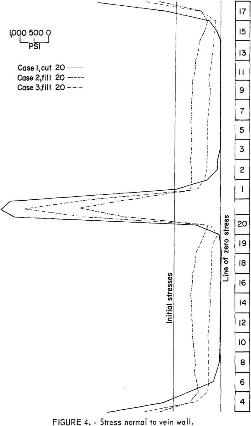
Three separate computer analyses were performed: an open stope and two backfilled stopes. The rock properties and mining sequence remained constant throughout while the backfill properties varied in each study. The results of the studies involving backfill were compared with the open stope to determine the relative performance of the different qualities of fill. Figures 3 and 4, respectively, illustrate the displacements and stresses normal to the stope wall that existed for each study after the mining sequence was complete. The displacements shown were for only one wall of the stope. The failure zones which occurred for each analysis are shown in figure 2. These failure zones are composed of elements in which the stresses exceeded the specific yield surface as determined by Mohr-Coulomb failure criterion. The zones are an accumulation of all the elements which yielded during the total mining sequence.
Case 1
An open stope analysis was performed in which no backfill was placed. The purpose of this study was to create a standard against which the
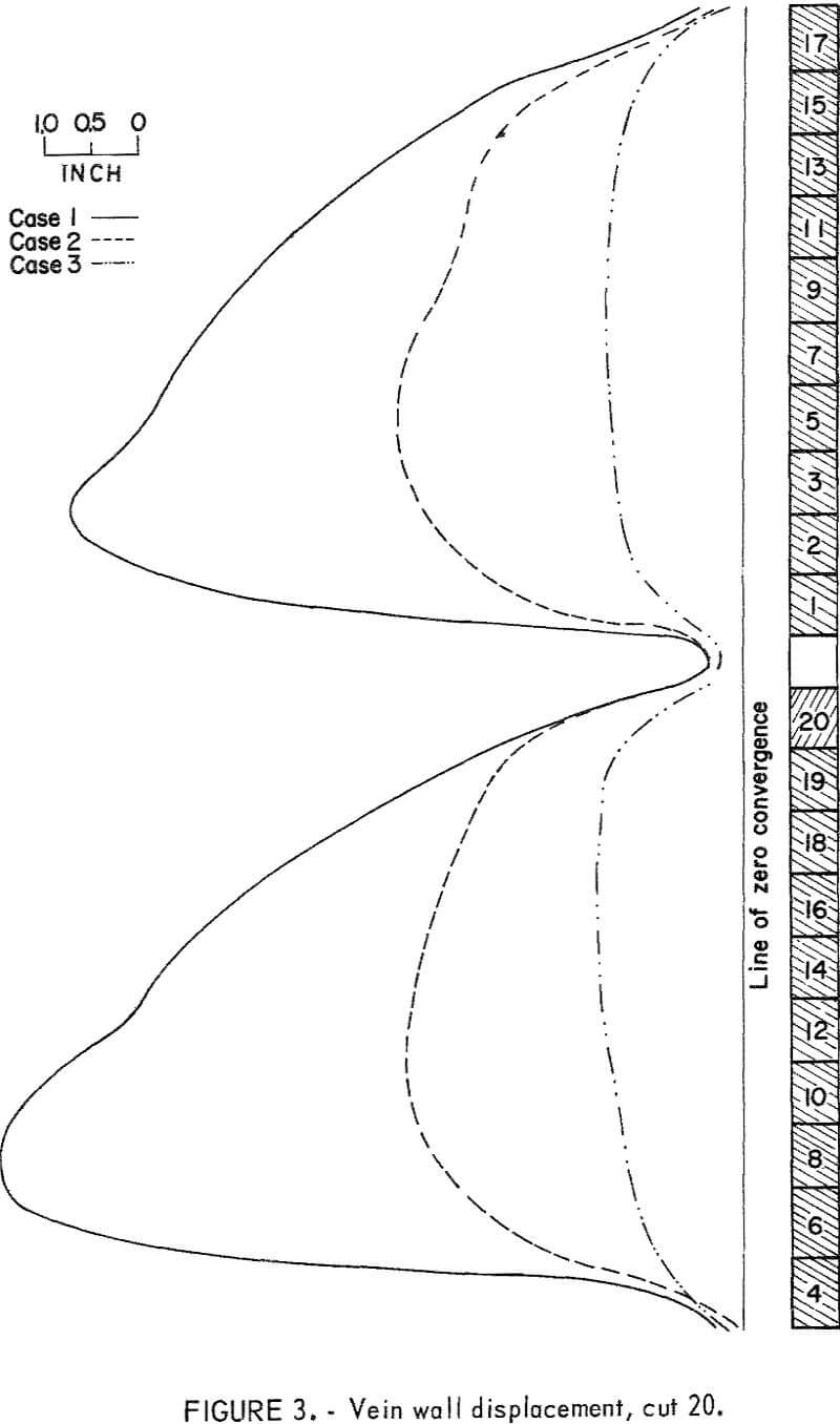
performance of the different backfills were compared. A maximum closure of approximately 8 inches occurred in one wall of the lower stope (fig. 3). Stresses normal to the stope wall were zero over the full stope height and reached a maximum of about 7,600 psi compression in the pillar area. Lower stresses are indicated in the sill of the lower stope and the back of the upper stope. The latter stresses would have been larger if mining of the higher elevations had been considered in the mathematical model. As indicated in figure 2, failure of the rock mass occurred over the full height of both stopes, with the exception of the region adjacent to the pillar. This is due to high confining stresses caused in part by the redistribution of stresses in the failure zones.
Case 2
The second analysis was made using the low-to-medium-quality backfill material. Maximum closure again occurred in the lower stope but was some 50 percent less than that of the open stope. The ability of this fill material to absorb some load resulted in compressive stresses building up normal to the stope walls with an accompanying decrease in stresses in the pillar area of approximately 11 percent. A significant decrease in the failure zone was also noted.
Case 3
The final study was made using the medium-to-high-quality backfill material. Maximum stope wall convergence occurred in the same region as the previous analyses, but the effect of this backfill was very pronounced with closures reduced 80 percent of the open stope and 63 percent of case 2. Reduction of stresses normal to the pillar area was also significant due to the better load-bearing qualities of this fill material. Zones of failure were restricted to the rock along the surface of the stope walls.
Comments on Computer Analyses
The results of these analyses indicate that, in addition to other benefits such as improving mine ventilation, controlling mine fires, and providing work platforms, hydraulic backfill can be effectively used for ground control. The results also indicate that better quality backfill alone would permit greater quantities of ore to be mined from the pillar before the rock burst situation became critical.
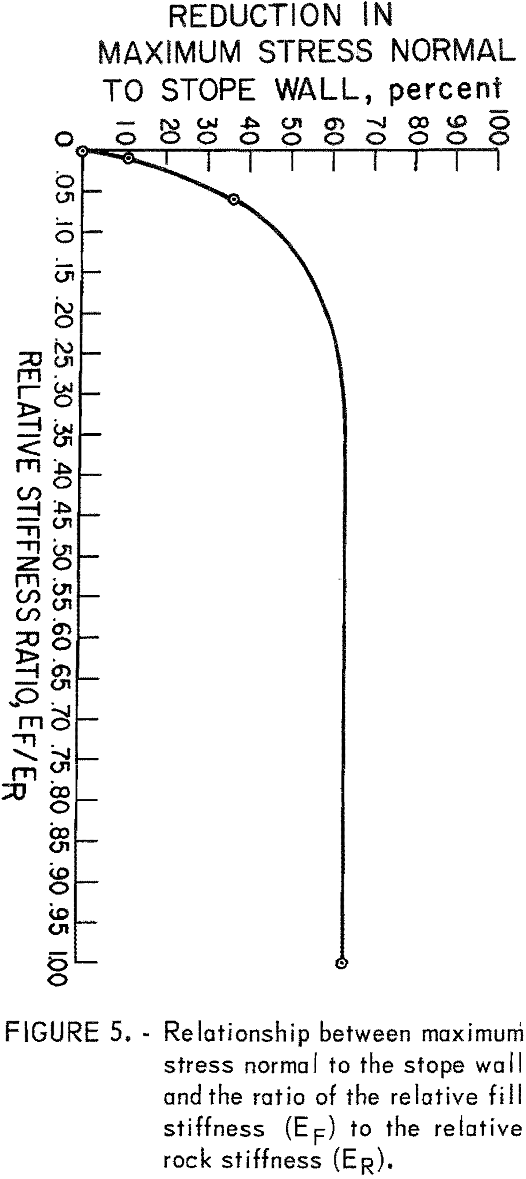
Areas of failure, stope wall closures, and stresses normal to the pillar are all interrelated. Figures 2 to 4 indicate these three items decrease as the quality of backfill material increases. Using the maximum average stress of the open stope as a base and computing maximum average stresses of the backfilled stopes as percentages of that base, a graph can be plotted relating maximum stress to the ratio of the relative stiffness of fill to rock. This value, which is the ratio of Young’s moduli (EF/ER), will be referred to as the “stiffness ratio.” Figure 5 is a plot of percent reduction in maximum average stress normal to the pillar versus the stiffness ratio. Four points were actually obtained on the stiffness ratio curve. The fourth point was with a stiffness ratio equal to one. This run was made solely to determine this point and was not included in the other analyses. Increasing the number of computer analyses to include backfills not previously considered would increase the accuracy of this curve, but the general overall shape would be virtually the same. This curve would be valid for this particular stope geometry, depth of mining, and mining sequence. Variation in any of these parameters would produce other similarly shaped curves. A separate family of curves could be plotted relating maximum stope wall displacement and stiffness ratios.
From this plot, it is evident that the addition of any backfill would produce some reduction in stresses normal to the pillar, but as the stiffness ratio decreases, there would be a point at which the benefits of reduced stresses would not justify the expense required to obtain that fill quality. On the other hand, as the stiffness ratio increases beyond 0.25, the curve flattens out; eventually a point would be reached where the cost of the backfill would equal the profits due to increased ore production. Between these two points there is an optimum range of stiffness ratios where backfill is most effective.
This plot also indicates that the effect of a particular backfill increases as the rock competence decreases, and that with very sound rock there may be no justification in backfilling for the purpose of ground control.
Comparing Computer Results and Field Measurements
The behavior of rock and hydraulic backfill in an actual mine is considerably more complex than that determined by the elastic-plastic analysis. This analysis neglects the effects of creep and relaxation, whereas mining is actually a time-dependent process in the sence that stopes require time to excavate, deform, and backfill. Other factors not considered in this computer program are temperature, nonhomogeneous and anisotropic materials properties, major geological features, fill drainage, and dynamic loadings due to blasting. Despite these shortcomings, the results of the computer analyses compare closely with field measurements.
Since the physical properties of the rock were reduced until predicted and measured stope closure agreed, an independent method of verification is the comparison of fill stresses. The predicted stresses normal to the stope wall at mid-height of the upper and lower stopes, with a backfill of Young’s modulus of 10,000 psi, were 515 and 562 psi, respectively. At an ore mine in the Coeur d’Alene mining district, it was found that these same stresses at mid-height of the stope ranged—from 480 to 620 psi as measured over a 3-year period. It can be concluded that the predicted stresses are of the correct order of magnitude.
Future Research
Finite-element analyses of cut-and-fill mining should be pursued along several avenues. The modification of programs to simulate cut-and-fill mining operations to permit consideration of the many physical variables applicable to soil and rock mechanics should receive increased attention. A few programs are presently available that are applicable to stope mining operations and are capable of taking into account geologic and time-dependent factors such as joint patterns, faults, creep, and relaxation. Effort should also be directed toward refinement of three-dimensional codes. It should be possible to determine the effect of placing artificial pillars in stopes. The strategic location of competent artificial pillars could significantly influence the redistribution of rock stresses from the pillar area to the artificial pillar.
Theoretical modeling should be advanced to duplicate actual mining sequences and to evaluate modification of typical cut-and-fill mining methods. Alternative possibilities that should be considered include the location of laterals, drifts, and crosscuts; preparation and construction of raise areas; modification of pillar thicknesses; location and position of initial stoping; and selection of most suitable backfill material. It should be further possible to determine an optimum mining sequence with respect to adjacent stopes as well as the vertical sequence of stoping. Development of time-sequence mining should result in the smallest pressure buildup through the pillar area on each mine level.
Another area of research interest would be to expand upon and improve the validity of the stiffness ratio concept by obtaining more data points on the stiffness ratio curve and then determining the stiffness ratio curves for other stope geometries. A family of stiffness ratio curves that could be described mathematically could be developed for the varying problem geometries. This stiffness ratio concept should be applied to other mining operations involving backfilling.
Finally, monitoring stope behavior and accumulating stope data must be continued to provide adequate information to compare theoretical and actual cut-and-fill operations. Work should be directed at acquiring data on individual stopes as well as on the relationship of each individual stope to the entire mining process. Detailed information should continue to be collected on each rock burst occurrence, and this data should be correlated with the available stoping information.
Conclusion
Hydraulic backfill can be effectively used for ground control. Furthermore, better quality backfill alone will permit greater quantities of ore to be mined from the pillar before a pillar rock burst situation develops. Hydraulic backfill is most effective in controlling stope wall closure, pillar stresses and areas of failure within a certain range of stiffness ratios. This optimum range of stiffness ratios can be determined by finite-element computer analysis for any stope when the physical properties of the rock and backfill, stope geometry, depth of mining, and mining sequence are known.
