Table of Contents
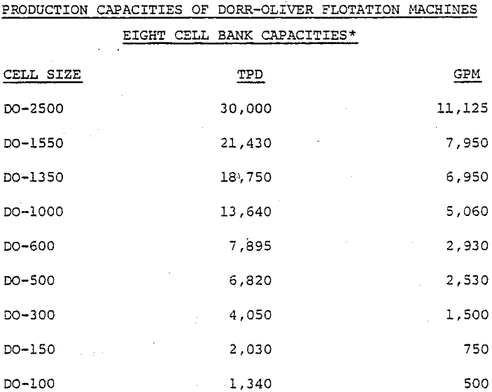
The development of larger size flotation machines, which started in the 1950’s and 1960’s, is still proceeding. The largest mechanical flotation machines available today have unit volumes in the range of 38.2 to 43.9 m³ (1,350 to 1,550 cft). Designs for mechanical flotation .cells of unit volumes as large as 70.8 m³ (2500 cft) are available. The development of these “giant” flotation machines has been and continues to be motivated by the increasingly critical forces of higher energy and capital costs, decreasing ore grades, and lower (real) prices for the products.
Design Considerations
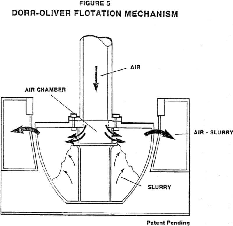
The prototype designs chosen for testing followed a vortex profile shape with air introduced via an air chamber cut into the top portion of the rotor core. Air is thus introduced directly into the pumping chambers where it comes into contact with high slurry flows across a large slurry-air interface.
The stator design selected featured a top ring from which short stator vanes were suspended radially about the rotor top section, which is the slurry discharge zone. The complete stator unit was fabricated in two halves for easy installation and supported by legs bolted to the cell floor. .
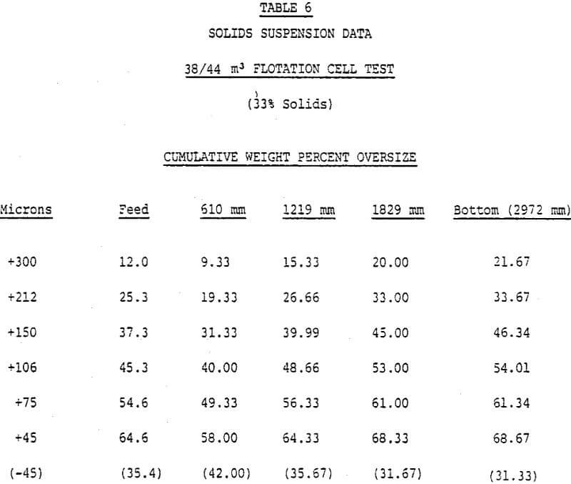
The cell tank design should aid the flow of the coarser solid particles toward the mechanism to assist in re-suspension. In the Dorr-Oliver design, the slurry is drawn across the tank bottom into the rotor, lifted and then expelled radially from the upper region of the rotor. A tank design which is markedly truncated or rounded at the bottom is therefore desirable.
This concept provides for a turbulent zone within the bottom 40 or 50 percent of the total tank height above which a “quiescent” zone is evident. This zone, being less turbulent permits the upward migration of mineral laden air bubbles with minimum opportunity for bubble/particle separation.
Development Programs
The complete development program involved three phases. The first two involved the appraisal of mechanical and physical performance parameters obtained from testing prototype designs at full scale production size. The third phase involved the process performance- testing of the chosen prototype design selected from the results of the first two phases.
Phase One – Design, manufacture and testing of a 2.3 m³ (100 ft³) cell mechanism
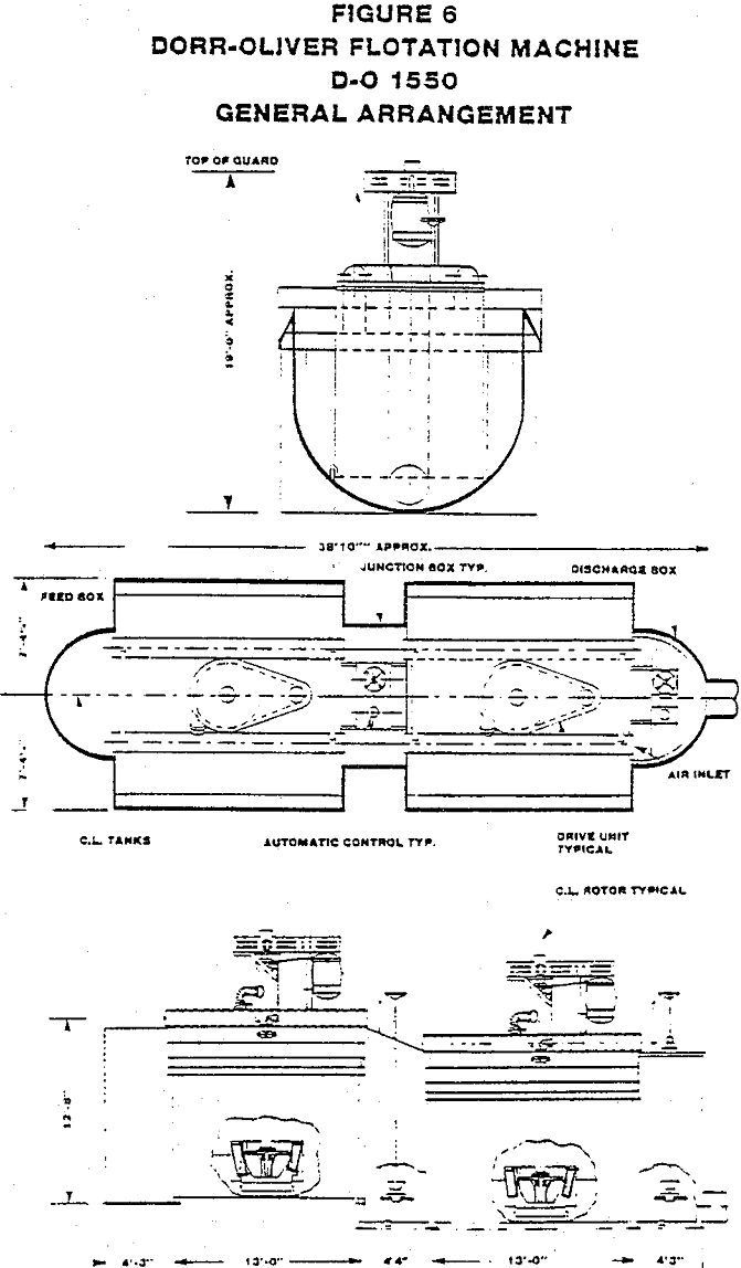
Phase Two – Design, manufacture and testing of a 38 – 44 m³ (1350- 1550 ft³) flotation cell mechanism
Phase Three – Process Testing of the Selected Mechanism
Results
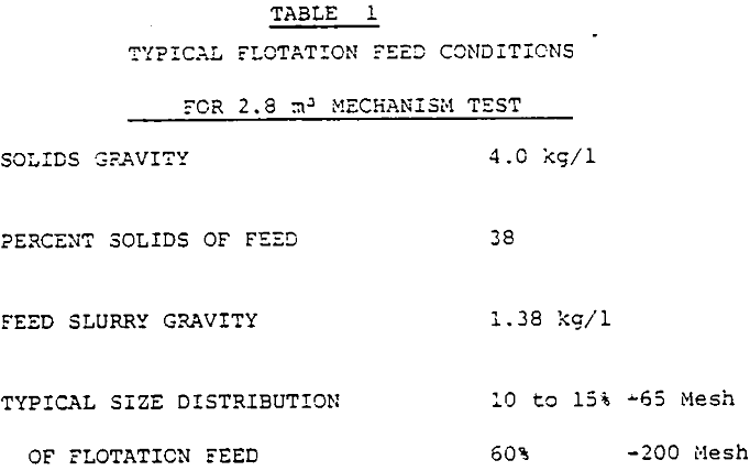
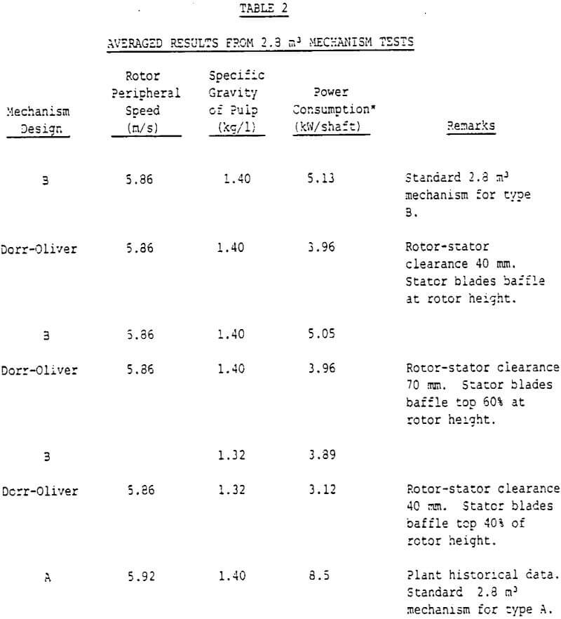
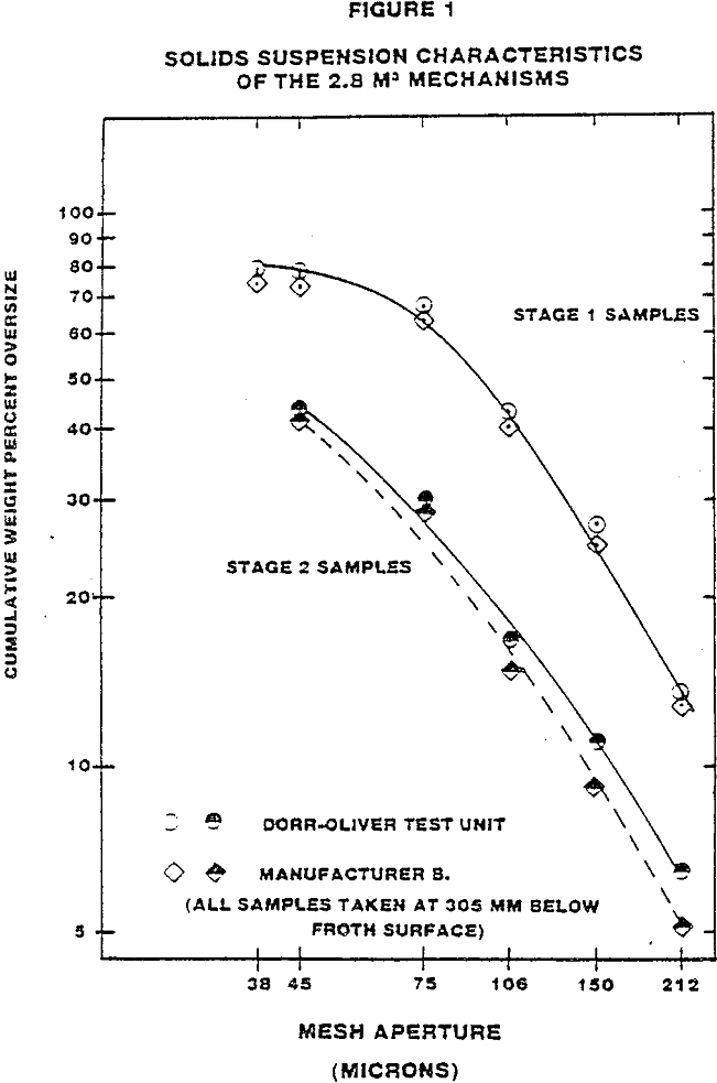
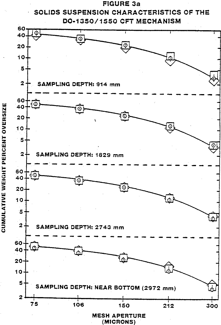
Initial testing to define the stator design parameters was done using two prototype mechanisms for 2.8 m³ cells. The test was run in a copper mill in the Southwestern United States, where the test units were installed in the first two of a six cell rougher scavenger bank. The last four mechanisms in this group were a different design (type B). A parallel bank of cells was equipped with a third type of mechanism (type A).
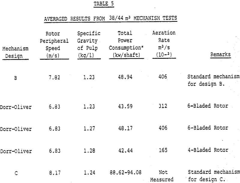
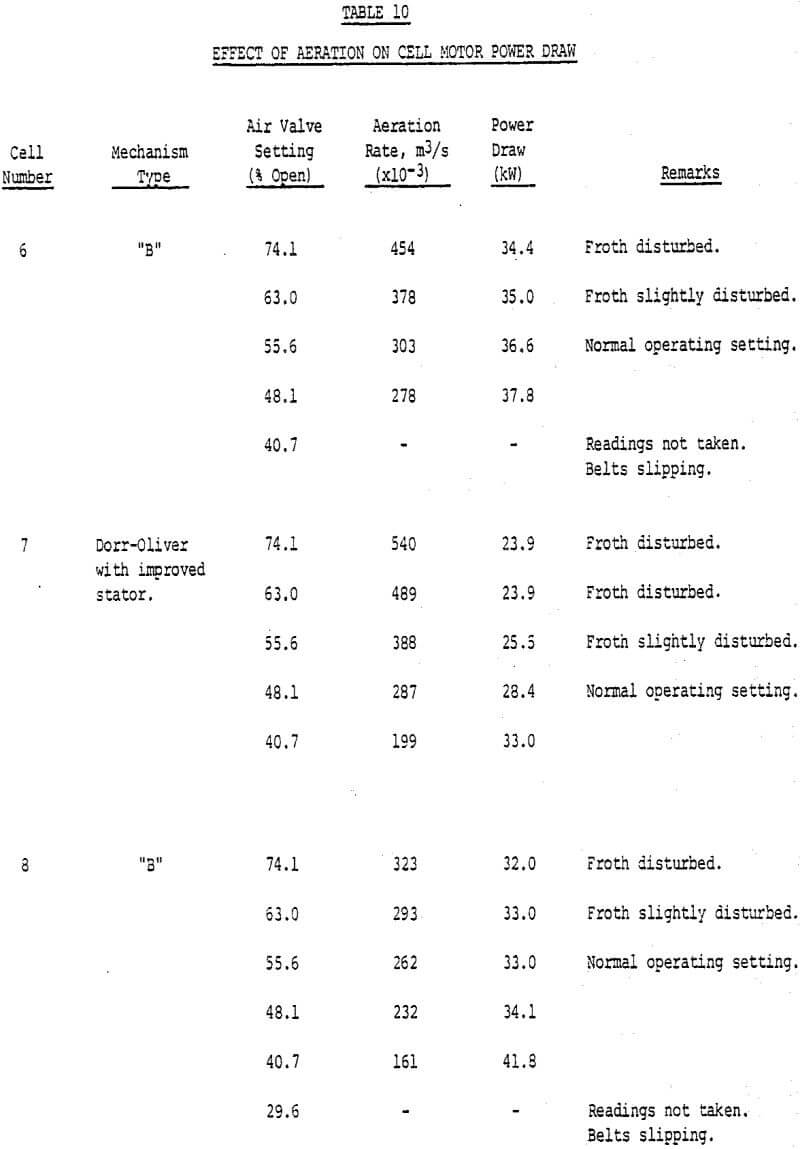
The machine used in this phase of the test work was originally fitted with a type B design mechanism. Table 5 shows an average total power consumption of 48.9 kW (65.58 HP) for this machine as originally designed. Air supply to the cell was 0.4 m³/s (860 ICFM) . Although there was some disturbance of the froth at this aeration rate, the customer found that if the air supply was reduced, the original mechanism could not adequately suspend the solids.
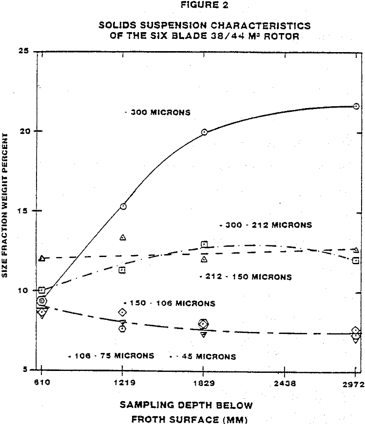
The first rotor tested was the six-bladed version. Because this rotor was originally designed for a 44 m³ (1550 cft) tank, the rotational speed was slowed to 145 rpm from the standard 160 rpm required for a 44 m³ (1550 cft) tank. From these tests, the following was learned about the six-bladed rotor.
After testing the six-bladed rotor, it was replaced with the four-bladed version. No other changes were made. Soon after start-up, it was evident that it could not disperse sufficient air nor could it adequately suspend the solids.
Hence the six-bladed rotor has been taken as the selected design at this time. It performed quite satisfactorily in a 38 m³ (1350 cft) cell at a speed of 145 rpm.
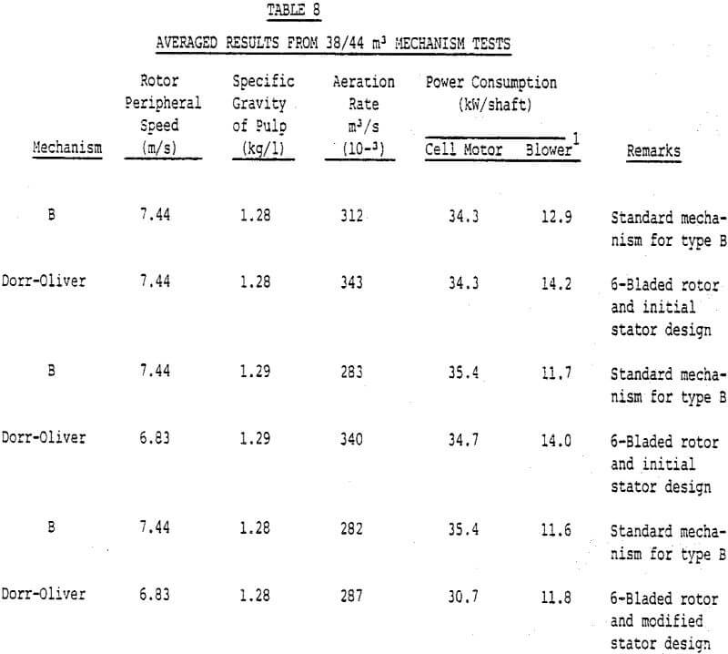
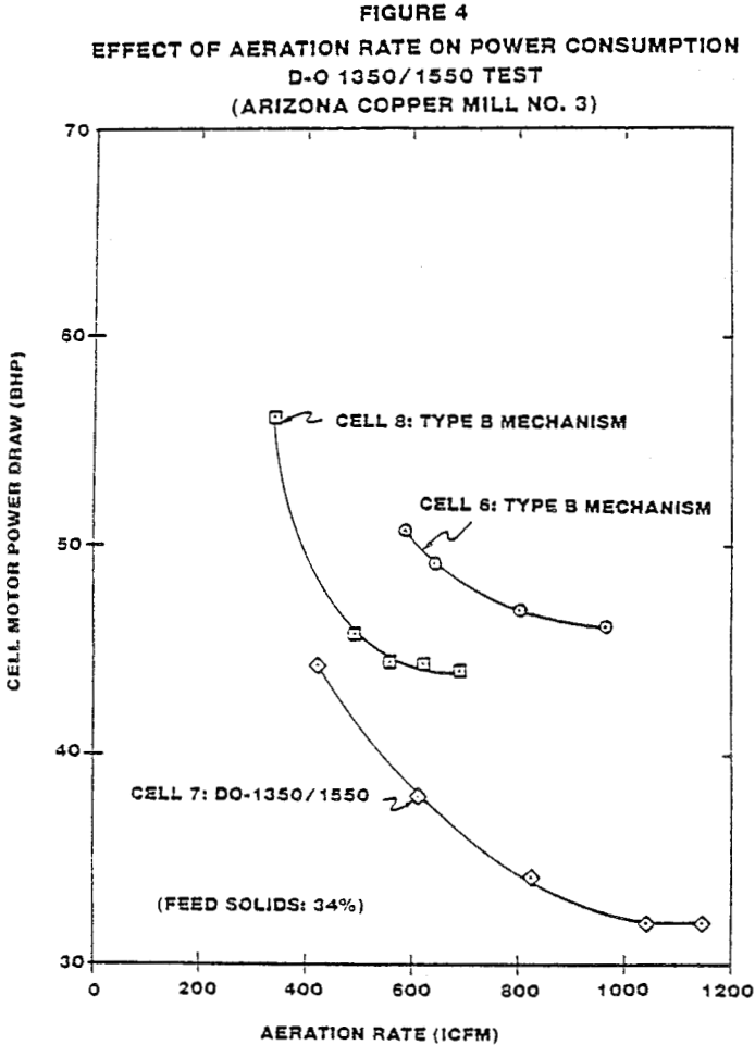
During the first part of this test, both the Dorr-Oliver and type B mechanisms were run at 158 RPM. The following was learned during this initial period: the cell motor’s power draw for both type mechanisms averaged 34.3 kW (46.0 BHP). This lack of power savings was inconsistent with previous results. The reason for this inconsistency became apparent during the shutdown to slow the DO-1350/1550 speed. The top support ring was observed to be interfering with the slurry flow from the rotor.
The next part of the test was to slow the rotor to the desired speed of 145 rpm.
At the time of this writing, we are working towards process testing to evaluate metallurgical performance in a row of large commercial cells at a couple of different installations.