Table of Contents
As a part of the Bureau of Mines research program to develop new mining methods for underground bedded deposits, a rock splitting tool capable of applying both radial and axial forces is being investigated as a primary excavation tool.
From the long-known hammer-driven wedge and ice expansion methods of propagating existing cracks in rock, mechanical splitting technology has progressed and now uses hydraulically actuated wedges operating in predrilled holes. Commercially available splitters are now used extensively in the construction industry for the demolition of concrete structures and to break boulders that are otherwise too large to handle conveniently.
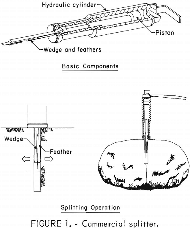
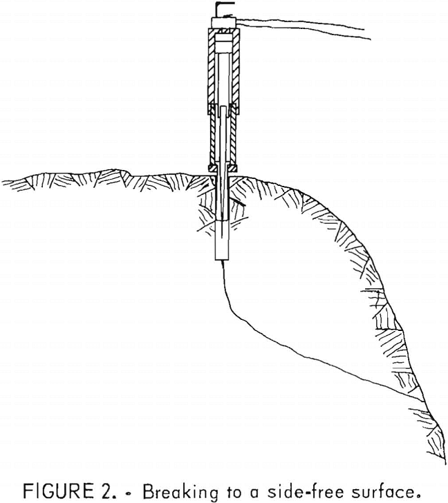
These commercial splitters are simple in design and operation, and consist of a double-acting hydraulic cylinder, twin feathers, and a wedge (fig. 1). In operation, the feather-wedge assembly is inserted into a predrilled hole, and the wedge is then piston driven between the feathers, forcing them outwards against the hole wall. This action causes a radially loaded stress buildup that fractures the rock along the plane dividing the feathers. However, if the rock has extensive dimensions in the plane of breakage, the fracture must turn from that plane and travel toward a side-free surface if the break is to reach completion (fig. 2).
The feasibility of using these splitting tools as a primary means of excavation in mining has been investigated. Methods of excavation were developed to mine panels and to advance
headings using side-free surfaces to increase their effectiveness. A longwall mining system for hard rock appeared the most promising. In this method, the face was advanced by moving down the longwall, as is typical in coal mining operations. The splitters were inserted in predrilled holes that were perpendicular to the face, breaking to the side-free surface created by preceding breaks. The principle of this method was field tested in a granite quarry by the Bureau and underground by Clark. In both trials, problems were encountered where fractured pieces were not dislodged by the splitter’s action. To relieve this problem, the Bureau’s researchers used an impactor to dislodge keyed rock fragments from the face; however, the difficulty of this dislodging process is increased when the fragment is confined on three sides. To counter this action, the Bureau proposed the use of horizontal slot cutting to create an additional free surface, eliminating the chance for this occurrence. A second, more difficult problem was encountered where there was a failure to generate a complete fracture (i.e., one that completely separates the rock fragment from the mass).
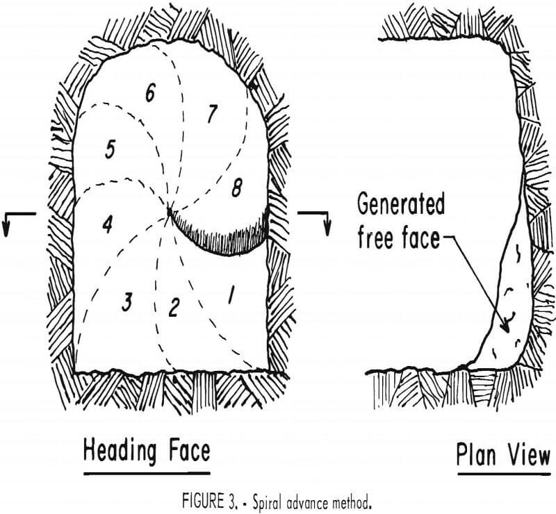
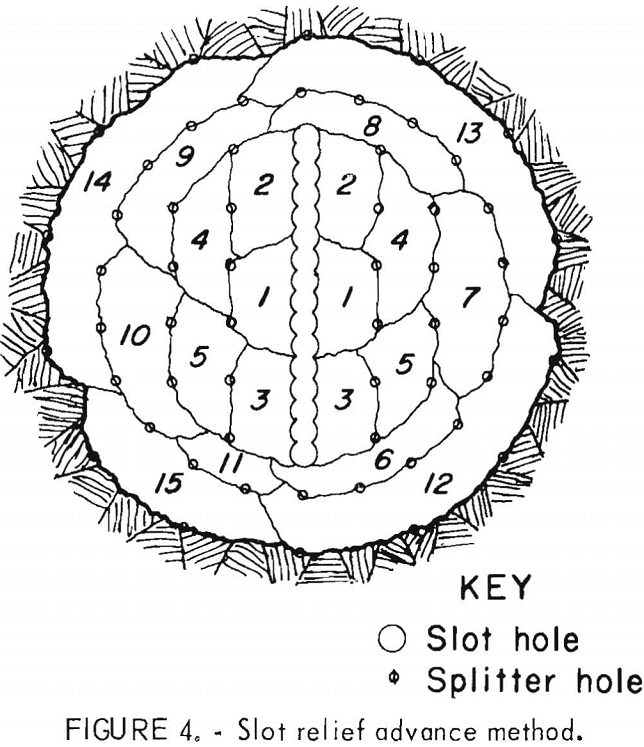
These problems were experienced with increased frequency during field tests in which the splitting tools were used to drive headings. Two heading advancement methods were developed. In one, the Bureau designed a technique to advance a spiral-shaped round (fig. 3). Once the spiral was initiated, the heading advanced with each succeeding round in a screwlike fashion. Due to the confinement of the heading and the requirement to break deeper than the available free surface, both repeated cycling and insertion of the splitters and compromises on the depth of break were necessary to generate complete fractures. In the other test, Clark excavated the face using a method similar to a V-cut explosive round (fig. 4). Central relief was first cut, and successive splitter breaks widened this opening. As with the Bureau’s method, difficulties were encountered in generating complete fractures.
Because of the uncertainties present concerning the use of splitting tools as primary rock excavators, the Bureau let a contract to study the potential applications of drill-split fragmentation systems in underground mining. This
study of the technical and economic feasibility of several types of splitting tools concluded that a tool developed by the Institute CERAC in Switzerland had the greatest potential. This radial-axial loading splitting tool differs from those presently used by the construction industry in that it generates fractures that propagate from an in-hole anchoring point back to the free surface of the rock face. This action provides a major improvement over splitting tools that require a free surface parallel to the drill hole to break toward; it all but eliminates the associated problems of their use.
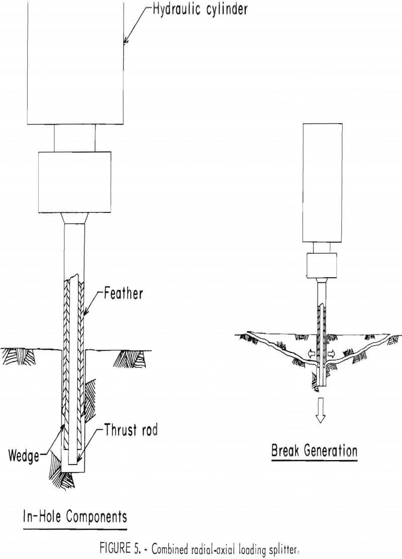
The tool uses its in-hole anchoring system and thrust rod to generate rock fractures (fig. 5). The anchoring system, which consists of a piston-actuated wedge and feathers, operates in a manner similar to that of an expansion-shell rock bolt and is able to fix the tool rigidly within a predrilled hole under radial load. The centrally located thrust rod, which is coaxial with the anchoring components, is piston driven to push off the hole’s bottom, thereby creating a zone of stress between the anchor and the hole bottom. This axial loading causes a fracture to run from its point of initiation at the anchor, generally parallel to the surface and then back toward the free surface of the rock face. The tool can also split in the manner of commercial splitters through the use of the radial loading capabilities of its anchoring components to break out to a parallel free surface.
Positive conclusions drawn about the radial-axial loading splitting tool in the contract’s final report reinforce those forwarded in two reports by Cooper and Rhyming of the Institute CERAC. Because little is known of this promising technology, a Bureau program was initiated to investigate the technical competence and capabilities of radial-axial loading splitting tools. Reduced-scale tools were designed, fabricated, and used in a laboratory testing program. Variables of operation were isolated, and sets of paired variable tests were run to define their influence on the splitters fragmentation effectiveness.
Specifically, the program studied the following variables and their influence upon the quantity of material removed and on the radial and axial forces required to produce breaks: the depth of break; the angle of insertion of the splitter with respect to the face; simultaneous breakage with two splitters; and the influence of radial and axial forces on each other and on the quantity of material removed, when treated as independent variables.
Tests were also conducted to develop techniques of drifting with the tool. A simulated drift heading was chosen because it posed the most difficult application for the tool, providing maximum confinement on the fracturing process. Within these tests, emphasis was placed upon developing techniques for advancing the drift and discovering the tool’s ability to maintain the drift’s gauge. Evaluations were also made of the influence that confinement has upon the other variables of the splitting process.
Equipment and Materials
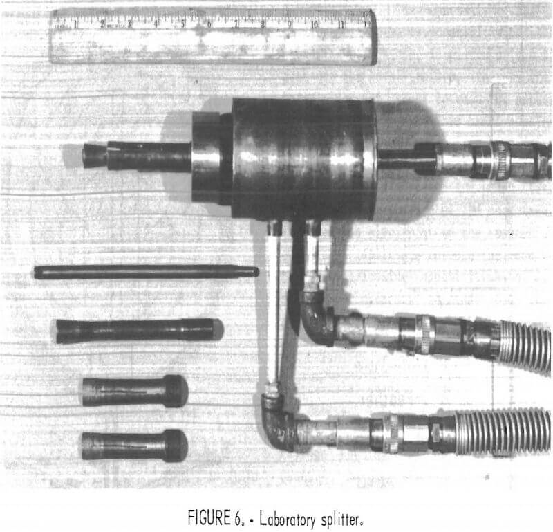
The two scaled splitters used in the program are identical, were patterned after those developed by the Institute CERAC, and are of simple design (fig. 6). As a mechanical excavation tool, the splitter is hydraulically actuated and incorporates two basic components: a hydraulic cylinder containing two pistons capable of independent movement, and in-hole components that affix to the pistons and the cylinder body itself (fig. 7).
The in-hole components are actuated by supplying fluid through ports A and C of the cylinder. Supply of fluid through port C causes piston E to move rearward
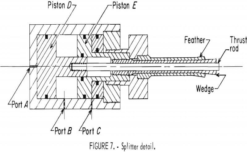
within the cylinder toward piston D. Fluid supplied through port A moves piston D forward within the cylinder and causes the two pistons to converge. The design of these two pistons is such that clearance is provided in piston E for the piston rod of piston D. Port B serves as the fluid outlet when either piston is actuated, and fluid supplied through this port returns both pistons to their rest postions. The hydraulic cylinder has a 2-in-diam bore that provides an effective area of 3.14 in² for the power stroke of piston D and an effective area of 2.54 in² for that of piston E.
The in-hole components, consisting of feathers, wedge, and thrust rod, are the mechanical means by which the splitter is anchored within the hole and a break is generated. This action is accomplished through the actuation of the pistons to which the wedge and thrust rod are attached. In operation, the wedge fixed to piston E is drawn back into the feathers, forcing them outwards and securely anchoring the splitter within the hole. Once this is accomplished, the thrust rod fixed to piston D is extended; when contact is made with the hole bottom, a stress buildup is experienced in the rock and the break is made.
The design of these in-hole components is critical for the effective operation of the splitter. Tool steels that were heat treated for increased hardness and strength were used for these three concentric components. The centrally located thrust rod has a 5/16-in-diam, a 7/16-in stroke, and works under loads up to 6,500 lb. The wedge, which has a 11/16-in stroke and works under loads up to 5,000 lb, is positioned with sliding clearances between the feather and thrust rod; it resembles a thick-walled tube from which emerges a cone-shaped end of 1-in length and 7° included angle. The feather, which is split axially into four equal components for separation and expansion by the wedge, has a cone-shaped end also, with an included angle of 3°. This taper enlarges to a maximum 5/8- in-diam at the feather’s leading edge and insures a close fit with a predrilled hole of just over 5/8-in diam.
A tapered feather was arrived at for the testing program, after the initial trials, using a feather with a raised cylindrical-shaped end of ½-in length, resulted in excessive anchor slippage. Together the wedge and feather translate the axial load on the wedge into a radial force exerted on the hole wall, defined by
R = A/N tan (θ + ∅)
where R = radial force on hole wall delivered by one feather leaf
A = axial force
N = number of feather leaves
θ = half of wedge angle
∅ = angle of friction between feather and wedge.
Under optimal conditions of wear and lubrication, a total radial force of approximately 31,000 lb can be placed on the hole wall. In the design of the wedge and feather, a compromise between hardness and brittleness had to be made. Originally, a soft wedge was used in conjunction with a hard feather; the result was a progressive material creep that rendered the wedge useless. Hardening of the wedge caused brittle failure of the feather at stress concentration points. A reduction in the hardness of the feather caused wear at the feather-hole-wall interface and material creep of the feather. Investigations are continuing to obtain the best compromise for these two components.
Each splitter is operated by two hand-powered hydraulic pumps; one is a single-speed pump with a manual load release valve, and the other is a two-speed pump with a manual, four-way, directional control valve (fig. 8). Each pump actuates one of the splitter’s pistons and sends the return fluid to the pump equipped
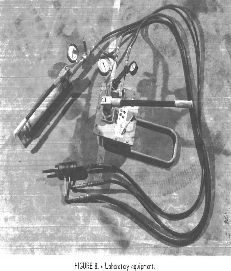
with the four-way valve. Repositioning of the four-way valve and release of the relief valve allow the two-speed pump to return the pistons to their rest positions. Equipped with gauges, the pumps offer excellent control over the fluid pressures supplied to the cylinders; they allow for slow pressurization and holding of the pressure without attendance. Sections of 10-ft hydraulic hose connect the splitters to the power units and permit flexibility in their use. Drilling of the 5/8-in-diam holes required by the splitter is accomplished with an electrically powered, 1.16-hp, rotary-percussive, handheld drill.
All testing was conducted in concrete blocks of 5,000-psi compressive strength; a mortar mix type of concrete was used with no aggregate present. Paired variable, independent tests were carried out in three blocks of 4- by 4- by 2-ft dimensions that were slabbed for additional trials when their 4- by 4-ft face was fully utilized. Simulated drifting operations were carried out in a block of 4- by 4- by 3-ft dimensions, entering in a 4- by 4-ft face and excavating a horseshoe-shaped opening of 22 by 2.2 in.
Procedures
The splitting operation begins with drilling the 5/8-in-diam hole required by the splitter. Although great accuracy inhole alignment is not considered crucial, attempts were made at keeping the alignment as close as possible to the desired angle with the face. Hole depth is a more critical aspect of the drilling operation. With the stroke limited to 7/16 in on the thrust rod, depth was closely monitored so that the rod would reach the hole bottom with sufficient stroke remaining to complete the break. In the paired variable testing program, tests were conducted on the flat surfaces of the concrete blocks and were spaced sufficiently so that breaks were independent of one another and of the block’s edges.
Before each use, the splitter’s in-hole components were inspected for excessive dirt and the status of their lubrication. Cleaning, as required, included removing the feathers from the tool and thoroughly cleaning them and the wedge of any dirt buildup. Lubrication, in the form of molybdenum di sulfide paste, was applied by brush to the wedge after each cleaning and as needed between cleanings.
When the splitter was placed in-hole its depth of insertion was measured and recorded. Fluid was then supplied for the actuation of the wedge, causing the splitter to anchor itself. The initial radial force applied was determined from experience with the depth of the break. Supply of fluid for the actuation of the thrust rod was then begun; this continued until the axial force buildup overcame the strength of the rock and a break was made. In many instances owing to either slipping or a greater radial force requirement, additional fluid was supplied to actuate the wedge during the actuation of the thrust rod.
Once the break was complete, the splitter was removed and the in-hole components were returned to their rest positions. Maximum cylinder pressures, corresponding to the maximum radial and axial force loadings, were recorded, as were the circumstances surrounding the break, its effectiveness, and any problems or peculiarities. Depending on the purpose of the test, paired variable or simulated drifting, break material was gathered for single breaks or in groups for weighing.
Results and Discussion
Data generated from the paired variable testing program were examined using regression analysis and analysis of variance techniques. Specific series of tests, used in each analysis are given within the subsections below. Data from the paired variable testing program are tabularized and listed in the appendix. Data from the simulated drifting operation will not be presented here because of the bulk involved and because, as a result of the lack of independence, they were not formally analyzed.
Influence of Depth of Break
The depth of break produced the great-est influence over and the strongest correlations with the dependent force variables. Break depth was easily controlled by regulating the insertion depth of the splitter; the break always began at the leading edge of the feather. Common breaking depths of 0.50, 0,75, 1.00, and 1.50 in were used to identify influence.
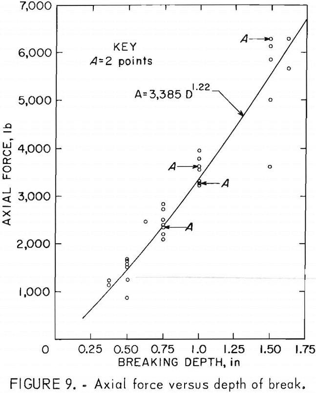
Regression analyses performed on these paired variables, for tests 82 through 115, found that power curves best describe their relationships. The function that best describes the relationship between the depth of break and the axial force is
A = 3,385 D1.22
where A = maximum axial force in pounds
D = depth of break in inches,
with a coefficient of determination of 0.91 (fig. 9). That which best describes the relationship between the depth of break and the radial force is
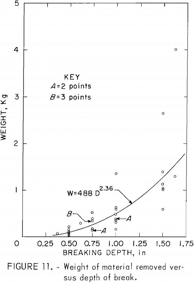
R = 10,451 D0.77
where R = maximum radial force in pounds,
with a coefficient of determination of 0.89 (fig. 10). These strong correlations indicate that the splitting tool can be designed for the expected working depth.
Break effectiveness was based on the quantity of material removed by the break. Under this definition, the depth of break produced the greatest influence on the tool’s effectiveness. Regression analysis found that this influence can best be described by
W = 488 D2.36
where W = quantity of material removed in grams,
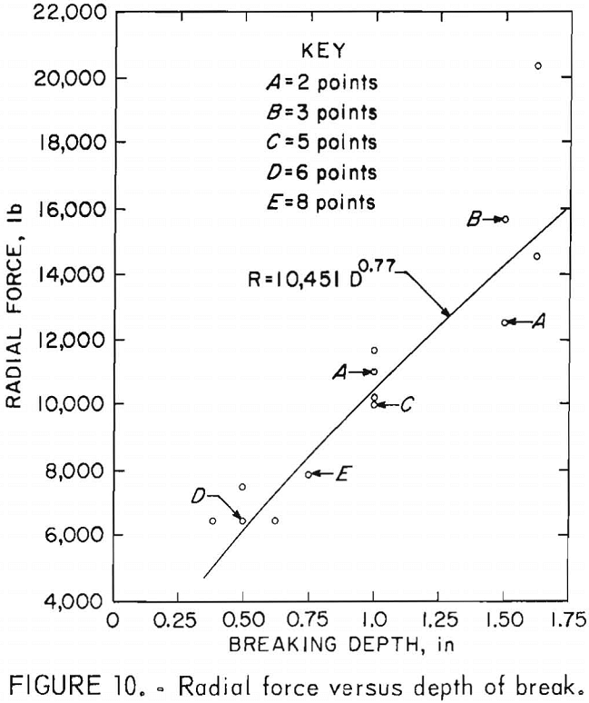
with a coefficient of determination of 0.75 (fig. 11). This correlation is lower than expected and is felt to be the result of material inconsistency, as break geometry is presumed to be reproducible in a homogeneous isotropic material under similar break conditions.
Influence of Insertion Angle
Inserting the splitter at an angle that deviates by as little as 20° from perpendicular to the face dramatically reduces break effectiveness. Figure 12 illustrates typical breaks at various angles and how the fractures will follow the path of least resistance to completion, rather than propagate into the mass. This action produces comparatively less than half of the material typically generated by a break made perpendicular to the face at the same depth; yet it requires approximately the same force loadings for the break to occur.
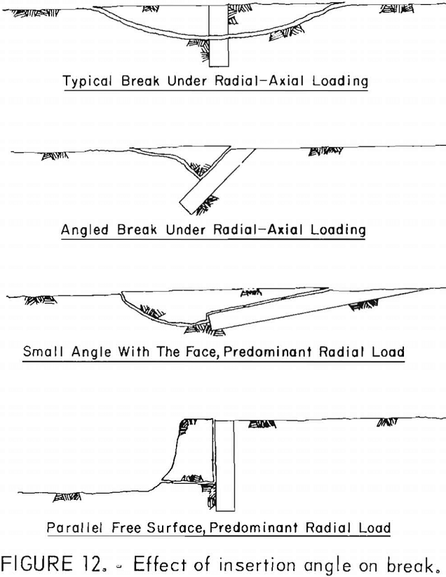
However, because the tool, like commercial splitters, can be operated under predominantly radial load, it can operate effectively at small angles relative to the face to produce planar fractures coincident with its own axis, or parallel with a side-free surface in a slabbing operation.
Influence of Simultaneous Breaks
The influence on break effectiveness of simultaneously operating two splitters was investigated for four breaking depths. From preliminary testing, a range of spacing was developed and used for each depth; operating out of this range reduced the effectiveness of simultaneous breaks. Spacing that became too close caused breaks similar to those from a single splitter, while increased spacing caused breaks to act independently. An analysis of variance was conducted for tests 1 to 81 (see appendix) at each depth, comparing double the quantities of material removed during single breaks with those quantities removed during simultaneous breaks. At the two shallower depths, 0.50 and 0.75 in, no significant increases in effectiveness were observed; however, at depths of 1.00 and 1.50 in, increases were significant, with confidence levels of 80 and 90 pct, respectively. This indicates that splitters working simultaneously at depths away from the immediate influence of the free surface of the face can favorably influence one another; their combined effectiveness can produce a significant advantage over their independent efforts.
Breaking simultaneously offers the advantage of removing as much or more material than two single breaks with less axial force input. An analysis of variance was completed for each depth to compare the axial force requirements of the two break conditions. Significant reductions were found in all cases. However, the confidence levels varied, with a low of 60 pct at 0.7 5-in depth to a high of 99.5 pct at 1.50 in of depth. These force reductions could mean reduced requirements on individual splitter output.
Influence of Forces
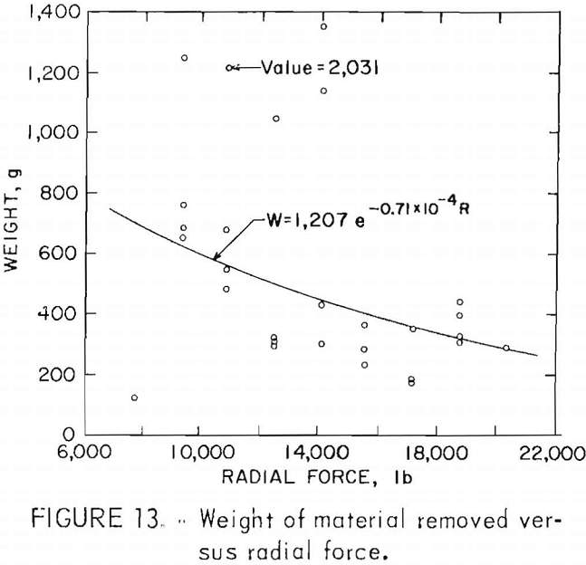
The influence of forces on the effectiveness of the splitter was studied for 1.00-in depth of break. Regression analyses performed on these variables did not show strong correlations. The analysis performed on data from tests 116 through 143 found that the exponential function best describing the relationship between the radial force and the weight of material removed is
W – 1,207 e-0.71 x 10 -4 R
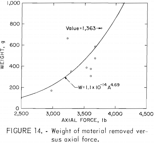
with a coefficient of determination of 0.14 (fig. 13). The analysis performed on data from tests 82 through 115 found that the function that best describes the relationship between the axial force and the quantity of material removed for the same depth is
W = 1.1 x 10 -14 + A4.69
with a coefficient of determination of 0.40 (fig. 14).
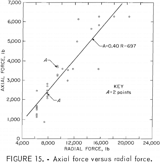
The relationship between the axial and radial forces was studied for tests 82 through 115. Regression analysis found a strong correlation between the maximum values attained for these forces. The linear function that best describes this relationship is
A = 0.40 R – 697
with a coefficient of determination of 0.82 (fig. 15), This strong correlation was expected. Typically the radial force was applied to prevent the splitter from slipping, and not as a mechanism to produce a fracture. Because radial force is tied directly to the amount of axial force applied, the strong correlation is produced. This indicates that a predictable loading combination exists under which breakage will occur, and that, by following that combination, breaks can be produced more efficiently and automation of the tool should be possible.
Influence of Confinement
The effects that confinement had on the splitter’s variables of operation were studied during the simulated drifting operation. The relationships developed during the paired variable testing
program were used as the basis for developing a plan of excavation for the simulated heading. Through operation, it was discovered that confinement was present in various degrees and was influenced by the contour of the face, the nearness of the drift’s perimeter, and the presence of fractures begun but not completed by previous breaks. It was also discovered that the confinement may be more or less for any particular break than what was present during the paired variable testing program. Quantifying the degree of confinement is therefore difficult at best and will not be tried here. As direct correlations cannot be made between confinement and the forces required to produce breaks, these relationships are addressed qualitatively.
The degree of confinement appears as strong a factor as breaking depths in relation to the forces required to produce breaks, with increasing
confinement resulting in increases in both the radial and axial forces required. The strong linear relationship developed between the radial and axial forces is not as evident here, owing to the number of breaks in which fractures were initiated under radial loading alone, thereby causing reductions in the maximum axial force required to complete the break.
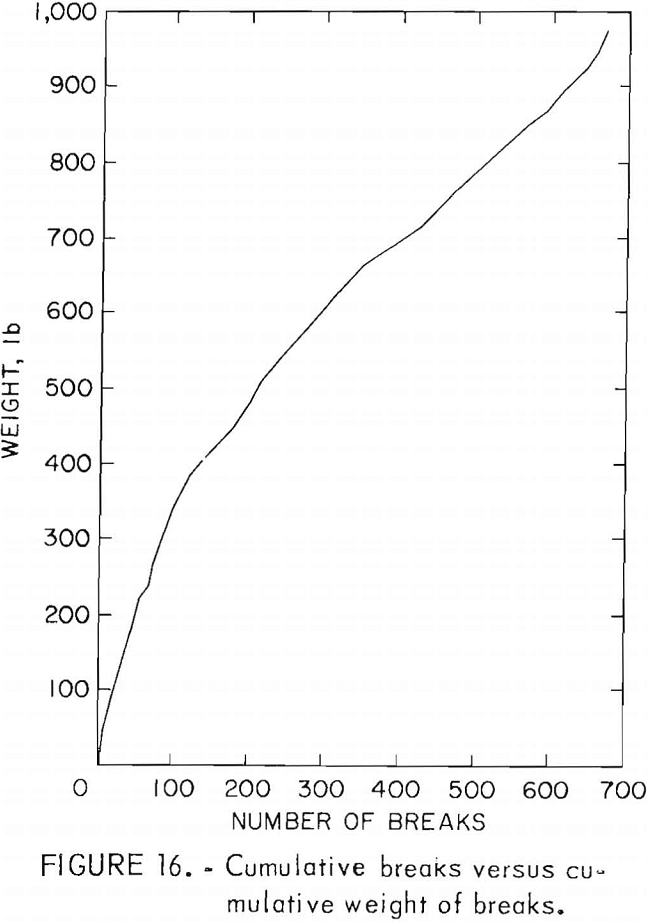
Splitter effectiveness, when confined, was based on the quantity of material removed by a series of breaks. Contrary to the paired variable program, the breaks were not independent and the mate¬rial removed was collected and weighed in groups. Figure 16 represents the cumulative weight of material removed versus the cumulative number of breaks made during the excavation of the drift. As can be seen by the change of slope of the curve in the figure, confinement reduces the effectiveness of the splitting process, from approximately 3 lb of material per break, for those conducted on the flat surface of the block in which the drift was initiated, to a steady state of approximately 1 lb per break.
Simulated Drifting Operation
Within this program, various techniques of drifting and gauging were developed for the splitting tool. Because of the limited testing completed, a best scenario of operation cannot be suggested; however, the techniques experimented with will be discussed.
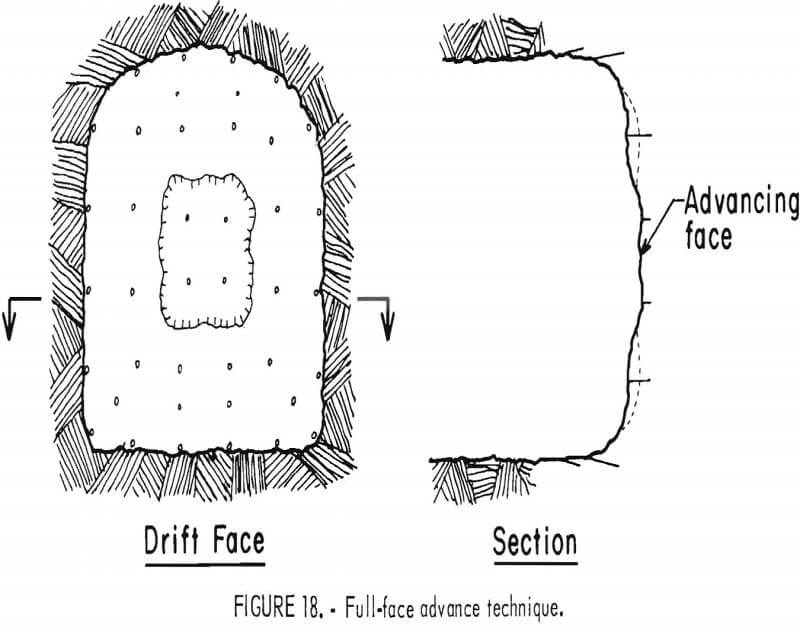
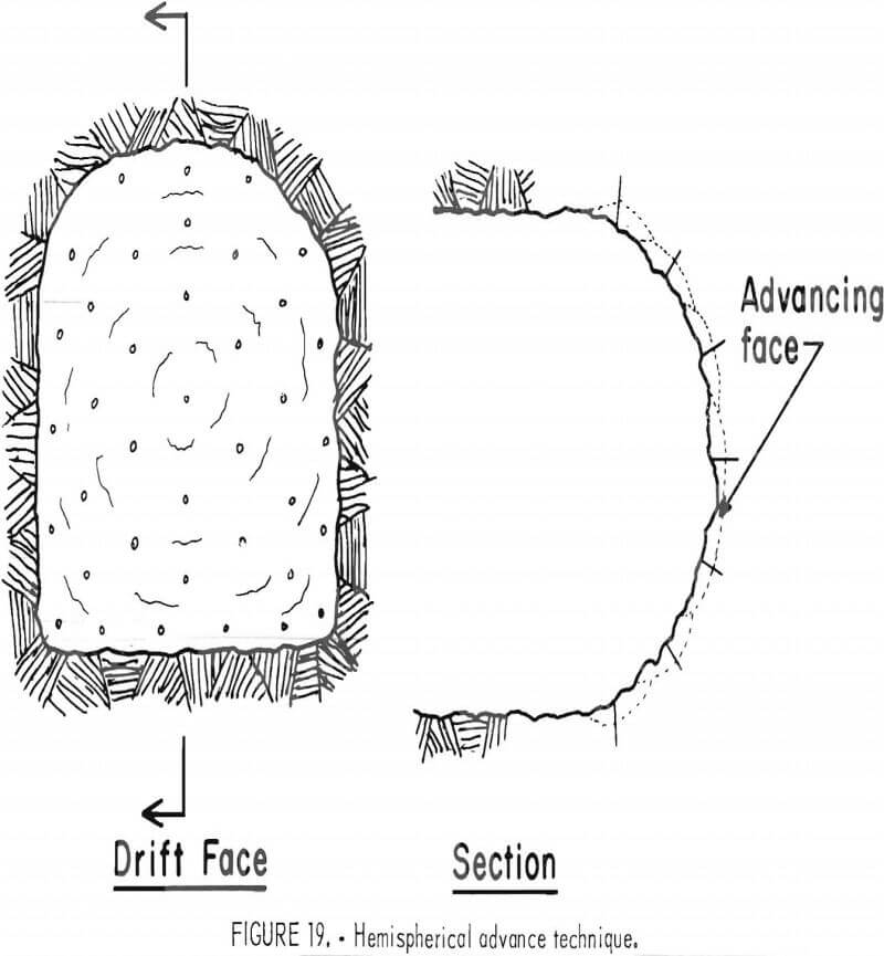
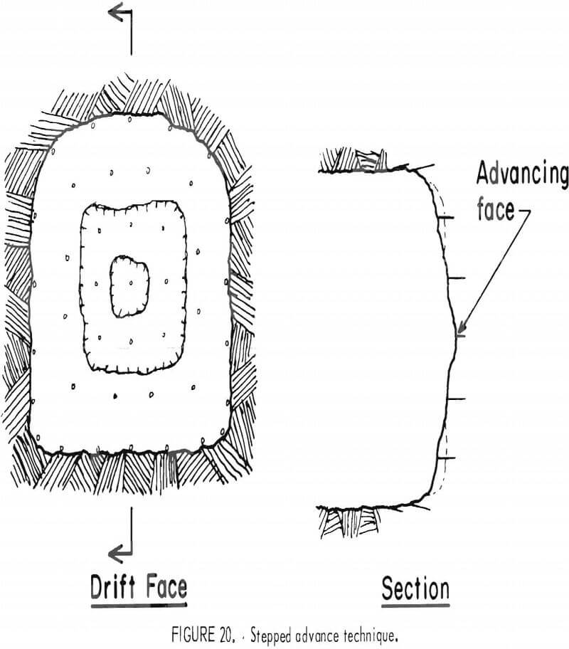
For advancing the horseshoe-shaped drift (fig. 17), three different techniques were employed: first, a full-face technique, which advances a planar face with successive breaks; second, a
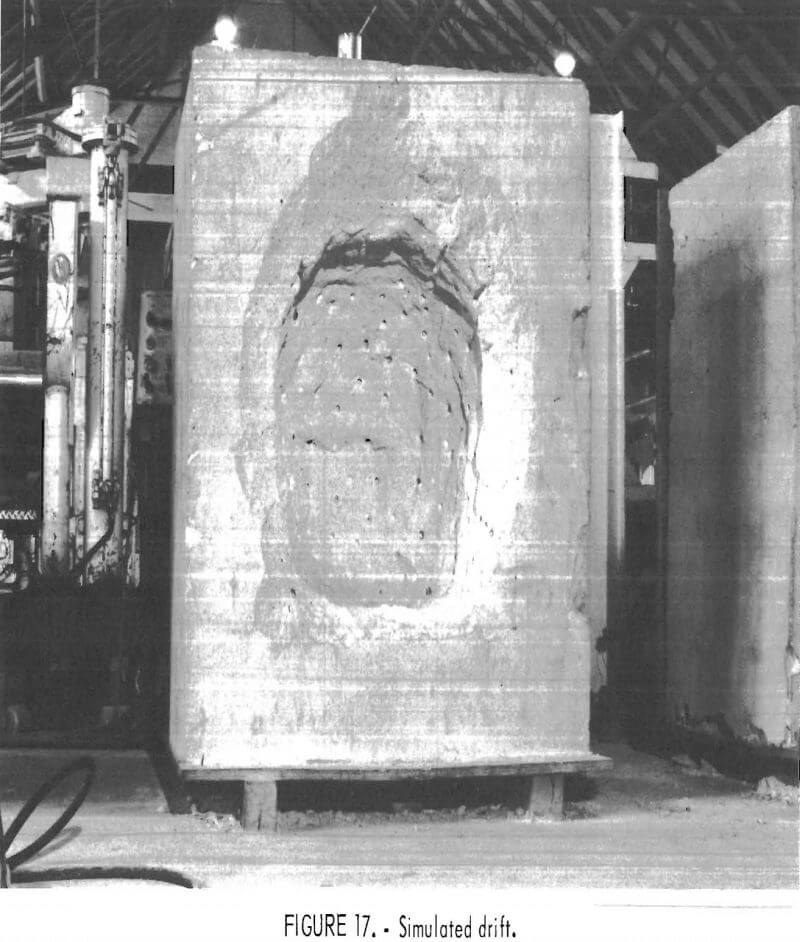
hemispherical technique, wherein, unlike the full-face technique where the splitter is inserted parallel to the direction of advance, the tool is inserted perpendicular to a developed hemispherical shaped face; and third, a stepped technique, which is a variation of the previous two, with the tool worked parallel to the direction of advance.
In the full-face technique, the center of the drift was advanced first, working outwards to the drift’s perimeter with successive breaks (fig. 18). With this technique, varying degrees of confinement were present, and different techniques of splitting were tried. Central breaks were made utilizing the tool’s usual radial-axial loading action. Successive breaks, made around this area and worked outward to the drift’s perimeter, were a mixture of predominantly radial or radial-axial loading methods. Both methods worked quite well, but the radial-axial method maintained the advance better.
In the hemispherical technique, the breaking process was initiated in the direction of the advance and worked around the hemisphere to the drift’s perimeter (fig. 19). With this technique, the face presented a fairly uniform degree of confinement throughout, and all breaks were made using the radial-axial loading splitting process.
In the stepped technique, the breaking process was begun as with the full-face technique. However, before one face was completed to the perimeter, a second was started (fig. 20). This method provided for more degrees of confinement than the full face method, and again a mixture of predominantly radial and radial-axial loading actions were utilized for producing breaks. With this method, the breaks deformed the stepped advance loosely into a wide-angle cone; both loading conditions worked equally well.
The ability of the tool to maintain the gauge and excavate the highly confined corners of the simulated drift were two areas of special interest. For maintaining the gauge, two techniques were used in conjunction with the advancing methods: first, slabbing, where the splitter was worked at a slight lookout angle; second, with the tool working at right angles to the advance, perpendicular to the perimeter of the drift. The former
utilizes predominantly radial loading; it functioned more effectively if the gauge was split a “round” or more behind the advance. The second technique utilizes the radial-axial loading capability of the splitter, with the drift’s perimeter as its working face. Here again, the technique functioned more effectively when working a “round” or more behind the advance.
The horseshoe-shaped drift allowed the splitter’s effectiveness to be assessed both in highly confined corners and around large-radius arches. The tool functioned effectively, easily maintaining the arch; however, the confinement of the corners proved difficult to excavate. Several techniques were tried in excavating the corners. In addition to variations of the two gauging techniques, the splitter was operated in the corners perpendicular to the direction of advance and at slight lookout angles. None of these methods proved very effective, and extra gauging breaks may be required in corner areas.
Among the drifting and gauging techniques employed, patterned and selectively placed splitting methods were tried, as were breaking simultaneously and with single breaks. Adhering to a strict pattern of breaks proved difficult unless that pattern provided an overkill of the area to be excavated. Selectively placed breaks worked more effectively but required a good working knowledge of the tool’s capabilities. A compromise between the two methods may be best, by relaxing pattern overkill and concentrating on troublesome areas.
Working simultaneously with a pair of splitters was more difficult within the drift, because the splitters were often subject to differing degrees of confinement. This required that forces applied to either splitter be individually tuned to its confinement for achieving good interaction. This proved difficult, and breaks were regularly made that were not simultaneous. However, these “double” breaks appear more effective when working in a confined area than breaks worked singly; and under radial loading conditions, splitting in pairs definitely worked better, especially when employing the lookout method of gauging.
Application of Results
The results obtained from the Bureau’s laboratory investigations were used to establish the energy efficiency of the splitting process and to predict splitter performance in driving a 10- by 10-ft heading, from which a cost analysis was made.
Energy Efficiency
The energy of excavating with the splitters is broken down into that used in drilling and that used by the splitting process. From Unger, the apparent specific energy of drilling concrete, at 5,000-psi compressive strength, can be approximated at 1,200 ft-lb/in³. Based on this figure, the energy attributed to drilling a 1.75-in-deep hole of 5/8-in diam is 7,730 in-lb. The energy required by the splitting process is based on the anticipated forces applied and their resultant displacements of the splitter components.
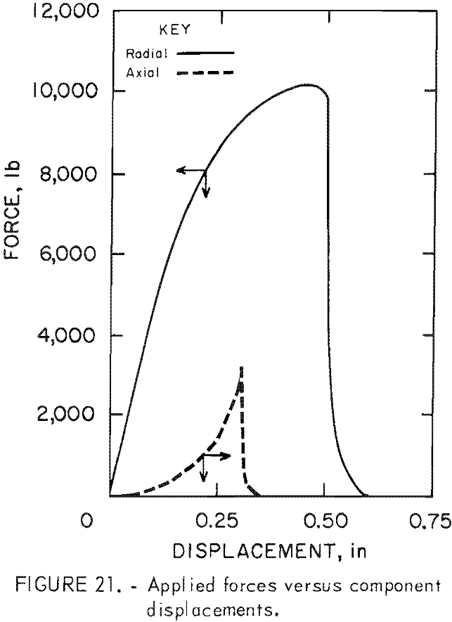
The curves of figure 21 exemplify the typical loading achieved during tests made at a 1.00-in depth of break. The energy required for splitting can be obtained by estimating the area under the curves. This process yields approximately 3,300 in-lb per break. The total energy required is, therefore, about 11,060 in-lb for the 1.00-in breaking depth. The typical volume removed by a break at this depth is 14.3 in³. The specific energy of the splitting process is therefore
Specific Energy = 11,060 in-lb/14.3 in³ = 733 in-lb/in³
This requirement should be reduced as the breaking depth is increased, because the overdrilling as a percentage of the breaking depth is reduced and the volume of material removed by any break increases faster than the forces required to produce the break.
The specific energy of splitting compares favorably with other large scale mechanical fragmentation systems with specific energies of 1,000 to 1,250 in- lb/in³ in 5 ,000-psi compressive strength material.
Excavation Rate
For comparative purposes, a scenario of operation was developed in which splitters would advance a 10- by 10-ft heading in hardrock. For the purposes of this analysis, only the fragmentation systems themselves were looked at, assuming that the subsystems of the development operation could keep pace with the splitter excavation process.
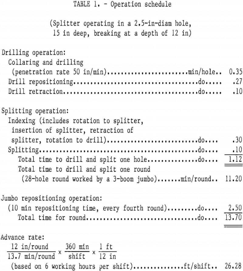
For excavating the heading, a single, automated jumbo carrying three booms and manned by two operators will be utilized. Each of the booms carries both a drill and a radial-axial loading splitter, and a rotating indexing mechanism to align the splitter with the drilled hole. The splitters break at depths of 12 in, and 28 breaks are required to advance the entire face area. These numbers are based on laboratory experience with the tool. Upon completion of every fourth 12-in advance, the jumbo itself would be advanced 48 in. The time required for advancing the entire face 12 in is averaged at 13.7 min, so the rate of advance is 26.28 ft per 8-hr shift (table 1). This compares favorably with other hardrock mechanical systems and with conventional drill and blast methods.
Cost Analysis
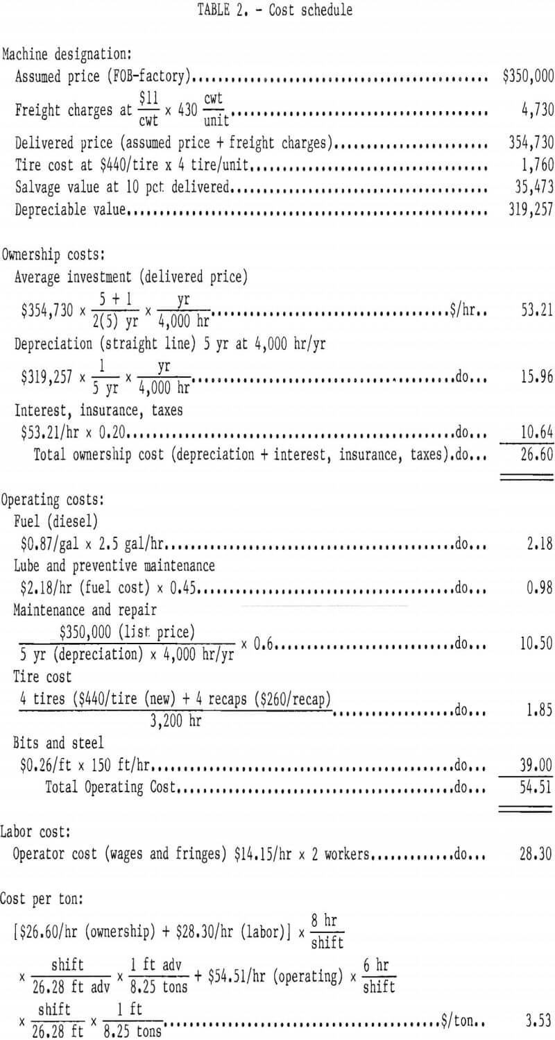
A cost analysis based on dollars per ton excavated was developed for the splitters for driving the 10- by 10-ft drift. The capital cost for the jumbo required is assumed to be $350,000. An advance rate of 26.28 ft per shift provides an excavation rate of 27.1 tons/hr. The hourly ownership and labor cost for the operation is $54.90 (table 2); this contributes a cost of $2.03 per ton of rock excavated to the operation. The hourly operating cost of $54.51, contributes a cost of $1.51 per ton of rock excavated to the operation based on a 6-hr working shift. The combined total for the operation is $3.53 per ton. This compares with a cost of $4.03 per ton, based on data from Larson, who used the same cost estimating procedure for driving a similar drift by drilling and blasting.
Conclusions
Because the experiments were carried out in one specific material, the predictive relationships established must be viewed under this constraint.
Because it directly affects tool capability requirements, the most critical relationship developed in the present analysis is that between the depth of break and the axial force required to produce that break. From the experimental data, it was found that the required axial force is proportional to the depth of break taken to the 1.22 power, or D1.22. This differs from Rhyming, who concluded that the axial force was proportional to the breaking depth taken to the 1.5 power, or D1.5. This difference is not significant at shallow depths of break; however, if the determined relationship holds for deeper breaks, it predicts significantly reduced force requirements at depths of 3 in or more.
Under typical radial-axial loading breakout conditions, radial force requirements to anchor the splitter increase linearly in response to axial force increases.
When operating at any particular depth, the quantity of material removed by a break does not appear to be sensitive to the radial or axial forces applied.
A stronger correlation was expected between the breaking depth and the quantity of material removed. The variation encountered may be the result of material inconsistency, degree of confinement (too near a block edge), or lack of a strict method of force application. Further investigation will be necessary to resolve this point.
The angle of splitter insertion has a pronounced effect on the quantity of material removed. When operating the tool under radial-axial breakout loads, angles of insertion of less then 20° from perpendicular to the face should be maintained. When operating at small angles with the face or in thin slabbing operations, a predominantly radial loading condition can be used effectively.
Simultaneous breaks provide a significant increase in splitter effectiveness when operated at depths of 1.00 and 1.50 in. Producing breaks in this manner also resulted in a force lower than the maximum expected for either splitter.
Confinement reduced the effectiveness of the splitting operation; an approximate reduction of 3 to 1 in the weight of material removed was found between excavating the simulated drift’s opening, and later working within its highly confined setting. Confinement also affected the forces required to produce a break, with increasing confinement producing similar increases in force requirements.
From the simulated drifting operation, the tool was found capable and effective at driving the heading and maintaining the gauge. Difficulties were encountered when excavating in the drifts corners; and new methods or tools capable of more force output may be required for efficient excavation of these areas.
The multipurpose radial-axial loading splitting tool offers major improvements over those tools that break rock exclusively under radial loads. They do not require a free surface paralleling the drill hole to break toward, which is a limiting factor in the design of excavations utilizing exclusively radially loading splitters; and they require no ancilliary equipment to unkey fragmented pieces. These factors both simplify the system design and reduce costs. In addition, the radial-axial tool appears capable of operating as effectively as the commercially available tools when working under radial loads only.
Laboratory testing has shown the drill-split concept with radial-axial loading splitters to be a viable alternative to drill-blast excavation systems. The results of the current economic analysis are encouraging and project a cost savings over drill-blast fragmentation when excavating in a confined heading. However, further investigations with the tool are needed to substantiate these projections.

