With particular reference to mill size, it is apparent that a change in diameter in a large mill is relatively far less significant than the same change in diameter for a small one. For example, using well established relationships between power draw and mill diameter and speed, 50 mm (2 inches) of liner wear results in about 14 percent power increase (at constant loading and rotational speed) for a 2.4 meter (8 foot) diameter mill, as opposed to only 6 percent for a 5.0 meter (16½ foot) diameter unit. If less lift for the charge also results, the net effect of the worn lining on power draw of the large mill may then be hardly noticeable.
The amount of grinding that actually occurs between the shell and the balls, as opposed to that between the balls themselves, may be deemed of interest in consideration of rubber lining materials, as well as with reference to mill diameter variation. The ratio of active mill shell surface area to ball charge surface area for the 5.0 meter (16½ foot) unit, is roughly half of that for the 2.4 meter (8 foot) unit. However, the actual ratios are so small (1 or 2 percent) that the amount of grinding at the shell is likely of little significance for either size.
Grinding of coarse feed material is a salient topic in consideration of the interrelationships between grinding mechanisms, ball action, and efficiency of grinding. The need for larger balls for efficient reduction of larger ore pieces indicates the need to effect a crushing action on these pieces, as opposed to a gradual wearing down associated with abrasive action. Similarly, the larger impact forces associated with higher rotational speeds have also been deemed responsible for more rapid reduction of coarse material than that obtained by rubbing (Taggart, 1945). The added advantage of utilization of higher speeds to achieve greater impact is not only that the penalty incurred with fewer, although larger, balls is avoided, but also that the incidence of media contacts is actually increased.
Consider, as well, that if a force applied to a particle is too small to cause breakage, the efficiency of the dissipated energy in terms of size reduction is zero. Although the efficiency of the breakage process may be small when a large force successfully breaks the same particle, the improvement is distinct.
Based on these observations the combination of mill speed and liner configuration that gives the highest practical ball trajectories is recommended for coarse ball milling. For fine grinding (normal rod mill product) mill efficiency and rotational speed are less interdependent (Gow et al, 1934), and therefore slightly reduced speeds may be desirable in order to provide a suitable balance between maximum power rating for a given size of equipment, and provision for future speed up to accomodate a capacity increase or long-range variation in ore characteristics.
Mill critical speed is defined as that rotational speed at which an infinitely small particle will centrifuge, assuming no slippage between the particle and the shell. The critical speed, Nc, in revolutions per minute, is a function of the mill diameter, D, expressed as:
Nc = 42.3/√D (meters) or Nc = 76.63/√D (feet)
In practical terms, one must assume some mill diameter, usually about 150 mm (6 inches) less than the mill inside shell or nominal diameter, that allows for the difference between the mill inside diameter and the location of the centre of gravity of the ball, as well as an assumed liner condition midway between new and fully-worn.
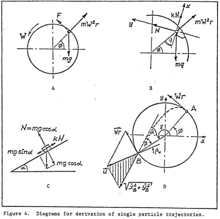
For coarse grinding, a mill speed of 75 to 78 percent of critical is recommended, depending on the initial lifter face angle. In this range, analysis of trajectories of balls in the outer row indicates a landing position corresponding to the most likely position of the “toe” at normal charge levels, midway between the horizontal and bottom extremities of the shell. This is not only important for obtaining maximum charge action, but also for avoiding destructive contact between balls and exposed shell liners. As well, these speeds correspond with a well-mixed charge, with a good proportion of both large balls and coarse ore particles in the peripheral section. At higher speeds, a noticeable segregation of the larger balls towards the centre of the charge occurs, which would result in abatement of impact forces provided by these media.
These are North American milling practice. In South Africa, for example, 90% CS is the standard in some autogenous milling plants, and various experimental work has indicated advantages in directly opposite directions, from extremely low to supercritical speeds.
Selection of liner thicknesses must stike a balance between a number of factors, including the following:
- a) Initial loss of effective mill diameter and volume.
- b) Wear life, or, interval between liner changes.
- c) Individual and total liner weights, for handling ease and mechanical loading of the mill structure and bearings.
- d) In the case of separate plates and lifters balanced replacement intervals.
- e) Possibility of breakage.
- f) Scrap loss.
- g) Manufacturing limitations.
- h) Loss of lifting profile as liners wear.
Note that all but the last factor would apply to both shell and end liners in performance of the function of protecting the mill shell and ends. Unlike shell liners, however, it is not the function of end liners to impart lift, and ribs on these are only provided to extend wear life of the plate portion by reducing slippage.
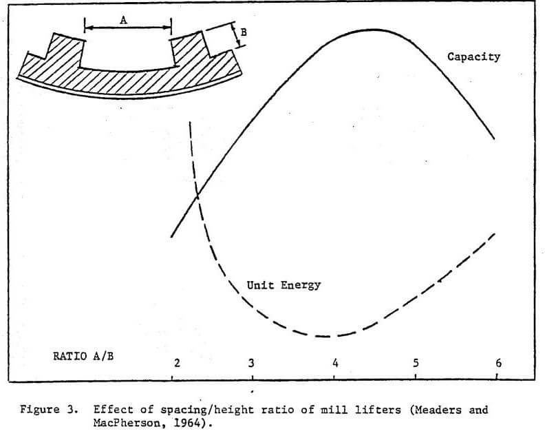
An optimum ratio of spacing to lifter height for an autogenous test mill was established by Meaders and MacPherson (1964), and successfully adapted to ball mill applications by at least two major rubber liner suppliers (Figure 3).
Once minimum lifter height is established, normally on the basis of the largest media size, spacing that will result in this ratio averaging about 4 to 1 over the wear life of the lining may then be selected. This ratio reflects a spacing that promotes desirable lift action without packing, as well as minimizing wear caused by slippage along the plate sections. Together with thickness and lifter face angle or shape, the liner configuration is then completely delineated.


