Table of Contents
By using the magnetization delay factor and the acquired momentum of the particle, minerals may be separated with magnetic susceptibilities within the diamagnetic susceptibility range. Unlike the rotating drum of the induced roll separators , and the feed belt of the cross-belt separators, which feed the particles in close packed moving layers, the vibrating feeder described here introduces the particles in a dispersed state, out of contact with each other.
Such dispersion utilizes the acquired particle momentum and permits the paramagnetic and diamagnetic particles to pass each other in the separation process. It also provides for the dry magnetic separation of ores at particle sizes smaller than the approximately 100-mesh (150-µ) limit of conventional separators, and much smaller if a vacuum ambient is economical. Upper limits in feed velocity can be increased at a greater rate than the increase in the lower limit of permissible susceptibility, since the feed velocity varies as the square root of the susceptibility.
Since no auxiliary high cost factors such as use of reagent, or use of scarce water supplies are needed, the separator may be used as a roughing concentrator directly on the ore as it is mined. This limitation to roughing is introduced on the possibility that the diamagnetic minerals may have a varying response owing to minute inclusions of magnetite.
Although dry magnetic separation does not require the added costs of reagents, or use scarce water supplies, the conventional form of separators have the disadvantage of not operating in a low magnetic susceptibility range at small particle sizes. This investigation for an improved separator is a continuation of the previously reported pioneering research of the Bureau of Mines which included the correlation of magnetic susceptibility with composition demonstration of the existence of a time factor in magnetization, and the design of low-loss, matrix-type separators. It involves calculations on particle dynamics, using the time factor in magnetization.
Basis of Design
The possibility of separating low-magnetic-susceptibility minerals at high feed rates is the result of using the magnetization time factor and the in-flight momentum of the deflected particle. By providing for the time for magnetization, the required magnetic field intensity is reduced and the selectivity for separating one mineral from another increased. The acquired momentum of the particle further reduces the required magnetic field intensity.
Magnetization Time and Field Intensity
Table 1 lists data derived from curves in reference 12 on the effect of preliminary field treatment in reducing the magnetic field intensity required for separation. Besides being of additional significance in changing the relative susceptibilities of different minerals, the reduction in required field intensity is of importance when the intensities approach the saturation value of the alloys used in the magnetic circuit. For hematite only 56 percent of the field is required after magnetic field pretreatment.

Magnetization Time and Separation Selectivity
Two processes occur simultaneously when particles are not pretreated in a homogeneous magnetic field: A force process resulting from the nonhomogeneous field and a magnetization process whereby the magnetic field increases the effective magnetization of the particles. The latter is a rate process; the degree of magnetization depends on the time the particles are in the magnetic field. Since the path for each separating particle is random, the actual magnetization would depend on the various random magnetic field intensities of the nonhomogeneous field through which the particle passes. The spectrum of the number of separated particles versus ampere turns would, therefore, be spread over a broad range. With a preliminary homogeneous magnetization field, the magnetization is substantially the same for every particle having the same composition. As a result, the tractive force in the nonhomogeneous field is effectively the same for every such particle, and the spectrum of the number of separated particles versus ampere turns is confined to a narrow range.
This may be expressed by the slope ΔW/ΔH of a curve where ΔW is an increment in the amount collected as magnetic when an increment ΔH is added to the magnetic field strength. The calculated values of table 1 show that the selectivity is highest with pretreatment in a nontractive magnetic field.
Utilization of Particle Momentum
The magnetic force on the particle is directed perpendicular to the force of gravity, and the effectiveness of the force is accentuated by utilizing the acquired momentum. This is illustrated by the equations,

The variables listed under nomenclature are in the cgs (centimeter, gram, second) system of units rather than the rationalized mks (meter, kilogram, second) system, although the latter is convenient when dealing with the combined action of electric and magnetic fields. Present practice is to retain the cgs system in applications to magnetic susceptibility.
The illustration of the effectiveness of the acquired momentum is simplified by introducing the restriction that the magnetic acceleration is of constant value, and that the particle has an initial velocity of zero. From figure 1A with horizontal magnetic acceleration,

Combining equation 3 with equation 4 and substituting y1 and y2 for t1 and t2 by equation 2,

If the magnetic force operates during the entire travel distance of the particle, Y1 = Y2, and with the simplifying assumption of x = Y1 equation 5 provides the solution, a = g.
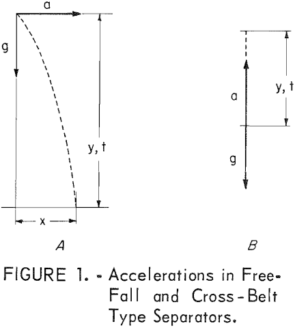
Upon adding a free fall distance of y2 = 10y1, the solution of equation 5 changes to, a = 0.19 g, representing an appreciable decrease in required magnetic acceleration as a result of the momentum of the particle. With the conventional form of cross-belt separators having the accelerations directed as in figure 1B, no particle movement occurs until a > g.
Procedure and Results
Construction Detail
The separator illustrated in figure 2 has a magnetic circuit of Armco magnetic iron comprised of cylindrical section 15 and rectangular sections 1, 12, and 13, with the
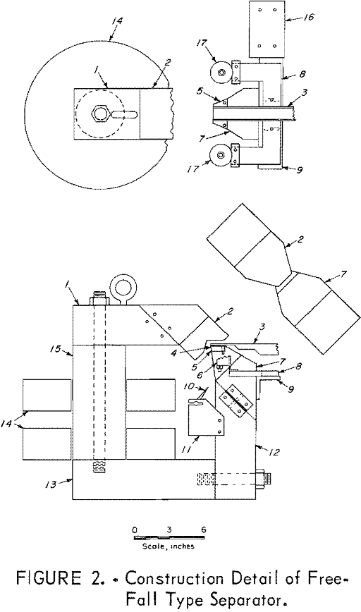
magnetic field generated by the water cooled coils 14 placed around section 15. Although the total number of wire turns was not known, the potential required for a 65-ampere current was 27 volts. The space for the separating field is provided by magnetic pole caps 2 and 7 of which pole cap 7 has an inserted section 5 of Permendur alloy to provide for the high concentration of magnetic flux occurring at this point.
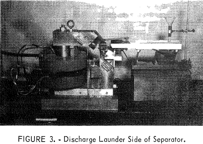
Particles are conveyed by vibrating feeder 3 so that the particles will fall close to the tip of A 0.19 inch wide and 0.035 inch thick Macarco neoprene-dacron moving belt 4 placed between the falling particles and 5 prevents any particle adhesion to the magnet pole. The belt is carried by flat faced pulleys 17 rotated at approximately 200 rpm by a motor and gearbox on base 16. Most of the belt support, including angle 9, frame 8, and bearing house 6, are constructed of nonmagnetic material such as aluminum. Action of the magnetic field results in different trajectories for the falling particles, and the adjustment of dividing edge 10, which is supported by bracket 11, provides for separating different magnetic susceptibilities into fractions. The position of the discharge launders is illustrated in figure 3. The last 3 inches of vibrating feeder 3 was constructed of plexiglass to prevent the vibration dampening by eddy currents which occurs with metals. The portion of the magnetic field through which the feeder extends, below the horizontal surface of 2, and above the horizontal surface of 5, is the homogeneous field for preliminary magnetization.
Experimental Results
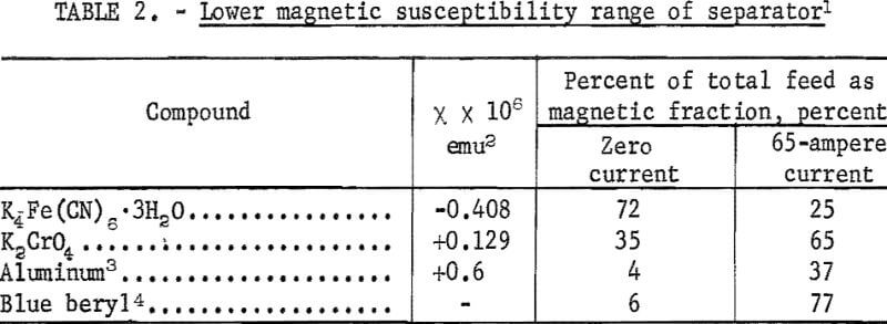
The lowest magnetic susceptibility mineral which is separable on conventional dry-type magnetic separators is represented by monazite. Estimated susceptibility from separator response is approximately 12 x 10 -6 emu. A number of compounds of lower magnetic susceptibility have been selected here to demonstrate the lower limits of the separator. These are summarized in table 2.
The green and yellow varieties of beryl have a low paramagnetic susceptibility like the blue beryl in table 3. The separation of a yellow variety of beryl from quartz and feldspar in an ore from Beryl Mountain, New Hampshire, is described in another reference 15. Although the paramagnetic susceptibility of yellow beryl is quite low, the divergence of the concentrate and reject trajectories is enhanced by the diamagnetic susceptibility of the feldspar and quartz.
With one pass through the magnetic separator, an 88.9-percent beryl recovery was obtained in a 19.0-percent beryl composition concentrate amounting to 9.9 percent of the feed weight. Feed and reject compositions were 2.1 and 0.26 percent beryl, respectively. The 19.0-percent beryl composition fraction represents a roughing concentrate. Recleaning of the concentrate was not very effective presumably due to magnetite inclusions in the contaminating gangue particles, a problem discussed in reference 11. Recleaning to a final concentrate can be made by the electrostatic method described in reference 10.
Both brown and green glass could be separated as magnetic from a minus 100 mesh (9 percent minus 200 mesh) glass sample derived from an incinerator residue fraction of the Bureau of Mines solid waste program. Operation of the vibrating feeder was at a linear feed velocity of 5.8 inches per second, the maximum imposed by the limited power input of the feeder drive. The nonmagnetic fraction represented a relatively pure colorless glass fraction which could not be obtained with conventional cross-belt and induced-roll separators, although part of the colored glass is in a sufficiently high range of susceptibility to be separable by these separators.
The broad range of colored-glass susceptibility is in contrast to specific minerals which are usually confined to a narrow range. A broad range requires repeated passes at increasing field intensity, otherwise the particles of too high a susceptibility have a tendency to accumulate on the vibrating feeder and beside the belt.
A minus-200-mesh hematite ore from Butt Mountain, Virginia, which contained a large amount of minus 325-mesh (44-µ) particles, did not flow at high feed rates in a dispersed state from the vibrating feeder edge. This is because the air viscosity restraint results in the air moving with the particles as a stream of homogeneous fluid. Viscosity will either reduce the initial velocity of a particle to zero after a certain stopping distance, or limit the maximum velocity the particle can attain under gravitational or magnetic acceleration. The terminal velocity of a spherical, unit-density particle of 50-m, diameter falling the 8.5-cm distance to the dividing edge is 127 cm per second in vacuum, and only 7.2 cm per second in air.
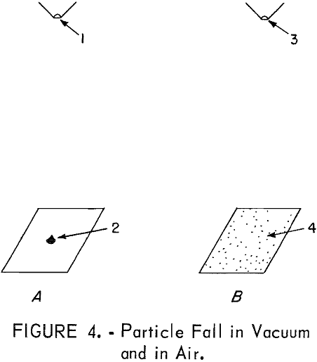
Further difficulty is encountered by the meandering path in air as was demonstrated by permitting small particles of microcline and quartz to fall a distance of 20 cm from the small apertures 1 and 3 of figure 4. In a vacuum of approximately 10 -7 torr, the particles deposited on a plane surface in a heap 2 of approximately 0.3 cm diameter. In a similar test in air, figure 4B, the particles were deposited over a large area. Bounce of the particles was prevented by the absorption of the rebound energy by particles already on the surface.
A partial vacuum ambient is not a solution since viscosity is independent of the pressure of gas. However, when the mean free path is comparable to the dimensions of the vessel, the viscosity effect disappears. For H2O and N2, the mean free path at 10 -4 torr is 30 and 50 cm, respectively. This suggests confinement of the particle-movement region of the separator to a space smaller than these dimensions.
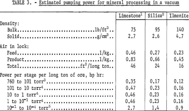
For vacuum production, economy is obtained by stage pumping at a series of air locks through which the ore passes. A pump at each stage evaluates a gas volume of, V P2/P1, where V is the air lock volume, and P1 and P2 are the low and high pressures, respectively, across the air lock. Calculations for five stages are summarized in table 3. If the calculations were based on each air lock being batch pumped, so that the pressure is gradually reduced from P2 to P1, a lower air lock pumping volume would result.
No estimate has been made on adsorbed gases. For air alone, the power required to reach a vacuum of 10 -4 torr is comparable to quoted values for froth-flotation machine drives. Adsorbed gases can be reduced by feeding the ore through the air locks at the coarsest size possible followed by grinding under vacuum. Further work is being conducted on the factors related to a vacuum ambient. Applications include grinding by the fracture of particles vibrating at high intensities and the adaptation of photoelectric effects to mineral separation.
Relative Effect of Various Variables
The magnetic moment of a particle in a magnetic field is equal to VH. In a nonuniform field with a gradient dH/dr, we have
![]()
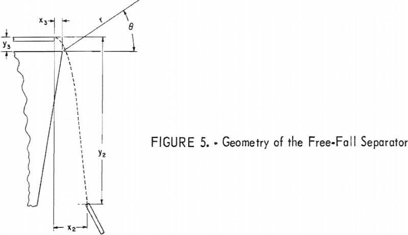
The closest approximation of the magnetic field lines near the wedge is represented by the radii of the arc of a cylinder shown in figure 5 as the field along a plane surface perpendicular to the cylindrical axis. With a radial field, the field intensities at the various radii are represented by the relation.
![]()
Expanding and eliminating the product of two differentials,
dH/dr = – H/r………………………………………………………(8)
and from 6,
![]()
It is convenient to express the field in terms of unit magnetic poles based on the theoretical possibility of gathering unit poles along the axis of a cylinder. With m poles per centimeter placed uniformly along the infinitely long axis, the lines of magnetic flux emerging from each centimeter of the axis is,
φ = 4πm……………………………………………………………..(10)
a relation arrived at by the analogy of electric and magnetic fields. In the mks system, equation 10 would have the form, φ = m. Dividing equation 10 by the cylindrical area per unit length provides the value,
H = 2mr-¹……………………………………………………………..(11)
Combining equations 9 and 11, the magnetic force is,
![]()
Comparing with gravity,

provides the value,
a = -X4m²r-³…………………………………………………………………….(15)
Referring again to figure 5, the action of the magnetic and gravitational accelerations is represented by two equations, the horizontal and vertical components of equation 2,

When treated as two simultaneous equations, the variable, t, cannot be simply eliminated, although a step by step calculation can be made as described in reference 10. However, from the geometry of the separator, x2 and y2 are constants. Simplification with the yield variables r and θ collected into two variables p and q, equations 16 and 17 change to,

Eliminating t2 provides the equation,

With the additional restriction that all variables except x and m are constant, equation 20 provides the relation,
Xm² = constant…………………………………………………………….(21)
The magnetic susceptibility varies inversely as the square of the magnetic pole strength. Thus, doubling the magnetic field will allow the separation of a mineral particle with one fourth the magnetic susceptibility.
A relation between vx and m can be obtained under two limiting conditions:
Condition 1
The undiminished horizontal velocity represents the initial vertical velocity by being changed from a horizontal to a vertical direction by the field. The path of the particle is further limited to a circle of radius r,
r = c cos θ……………………………………………………………(22)
and eliminating cos θ by equation 22,

this simplifies to,

Since c is the distance covered in time t1 at a constant velocity vx, or c = vxt1, equation 25 changes to,
vx = H(X/2)½……………………………………………………………….(26)
The feed velocity varies linearly with the magnetic field strength.
Condition 2
The horizontal velocity of the particle is reduced to zero by the field without contributing to the vertical velocity when the equation 19 term,

This is theoretically possible when θ varies in both directions from its zero value. Since there is no vertical velocity component after t = t1, equation 18 is independent and changes to,

If the stopping distance x2 remains constant, the particle path is unchanged with the result that the value, p, is constant.
Equation 28 then has the value.
![]()
Since x2 is the distance covered in time t1 at a constant velocity vx , or x2 = vxt1, the value of vx from equation 29 is,
vx =m(2Xx2p)½………………………………………………………………..(30)
Similar to the result obtained with limiting condition 1, the feed velocity varies linearly with the magnetic field strength. This relation combined with equation 21 provides a relation between feed velocity and magnetic susceptibility whereby the feed velocity varies with the square root of the magnetic susceptibility. For a lower limit of permissible magnetic susceptibility, doubling the maximum limit of feed velocity will increase the lower limit of magnetic susceptibility only 1.4 times.
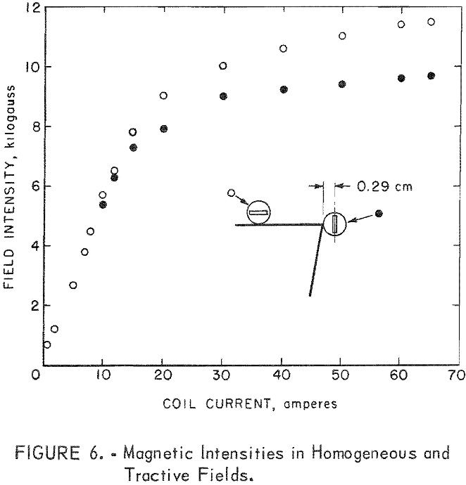
Field intensities were measured with a Bell model 300 gaussmeter. The positions of the probe, a flat Hall-effect element inside a 0.23 inch diameter tube shield, are shown in figure 6. The position at the top of the wedge pole measures the field intensities in the homogeneous field, while the position adjacent to the wedge tip measures field intensity in the nonhomogeneous field. The curves in figure 6 show that the portion of the magnetic pole for the homogeneous field is far from saturation at a 65-ampere coil current.
For the wedge tip, a distance of 0.29 cm from the tip provides a field intensity of 9,700 gauss at 65 amperes. The saturation magnetization for Permendur alloy is approximately 24,000 gauss; calculation by equation 11 shows that the value of 24,000 gauss is reached at a distance of rs =0.12 cm. Distortion from an ideal radial field evidently occurs in close proximity to a sharp edge tip. By rounding the tip with a radius of curvature of rs = 0.12 cm, a radial field may be maintained.
A value too large for rs is detrimental. Although the theoretical unit poles per cm increases with rs, as shown by use of equation 11,
2m = Hsrs……………………………………………………………………….(31)
the eventual required increase of rt , where rt > rs, decreases the magnetic acceleration. By equation 15

If the wedge tip is magnetically saturated and the particles pass through the field at an arbitrarily selected distance of 0.2 cm from the tip surface then,
rs = rt – 0.2…………………………………………………………………….(33)
Equation 32 changes to,

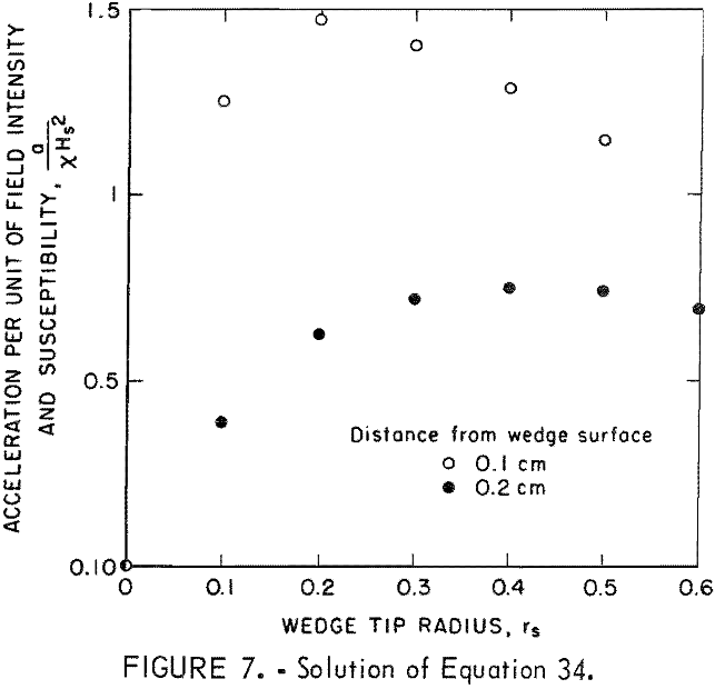
The solution of equation 34 in figure 7 shows a maximum in the magnetic acceleration at certain radii. For a distance of 0.2 cm from the wedge, a maximum occurs at rt = 0.6 cm or rs = 0.4 cm. Similarly for a 0.1-cm distance, rt = 0.3 cm, or rs = 0.2 cm. The decrease from the maximum for large values of rt occurs as a result of a decrease in field gradient expressed by equation 8, while the decrease from the maximum for small values of rt is the result of the decrease in the number of unit poles, m, expressed by equation 31.
One compensating factor not noted in these calculations is that an increase in rs results in an increase in available magnetic field space with subsequent longer times for magnetic acceleration. Performance at low magnetic susceptibilities may also be improved by increasing the homogeneous field intensity and the time in which the particle is retained in this field.
