Table of Contents
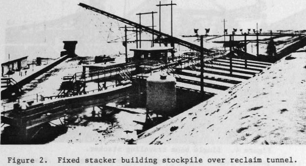
Whenever the material and soil conditions permit its use, a belt conveyor in a reclaim tunnel is the most economical reclaim device due to its very limited manpower requirements and utilization of gravity to make the ore flow to the feeder opening. This dependence on material flow limits the belt conveyor in a reclaim tunnel to materials that are not sticky and will not hang up in the stockpile. For sticky material applications, reclaim should be by front end loader or bucket wheel reclaimer.
Since relatively simple linear reclaim conveyor layouts are usually used in conjunction with conical stockpiles and elongated stockpiles, the following sections are concerned with reclaim conveyor layouts for radial stockpiles.
A discussion of feeding devices for belt conveyors in reclaim tunnels is beyond the scope of this paper and is, therefore, not included.
Single Tunnel
As indicated, the single tunnel reclaim conveyor is most efficiently applied to a radial stockpile when the stacker moves through a 60 degree arc. As indicated previously, this size stockpile could have a maximum capacity in the range of 61 000 metric tons (67 000 short tons) if the allowable soil bearing pressure were 14 680 kg/m² (3000 lb/ft²).
Sequential Tunnel
For stackers with an arc of greater than 60 degrees, reclaim conveyors in sequential tunnels provide greater reclaiming capacity. In this arrangement, the reclaim tunnel from one section of the pile intersects the tunnel for the next conveyor at an angle. The first conveyor discharges onto the tail end of the next conveyor. In this manner, the reclaim conveyors roughly follow the curve of the stockpile. The sequential system has the advantage of not requiring a collecting conveyor but has the disadvantage of making the first reclaim conveyor dependent on the proper operation of the downstream reclaim conveyors and has a transfer point under the stockpile. Such transfer points can sometimes be a source of problems and should be avoided if possible.
Converging Tunnels
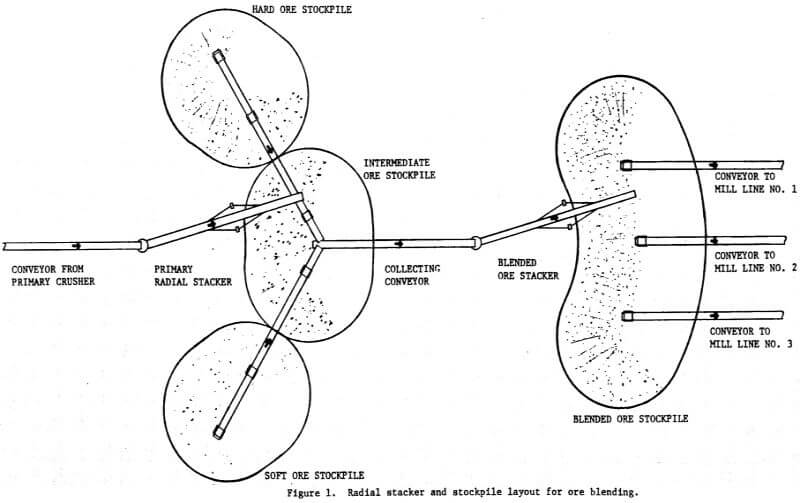
An alternate to the sequential tunnel layout is the converging tunnel arrangement. In this arrangement, the reclaim conveyors feed to a central collecting conveyor which transports the ore out from under the stockpile. The tunnels for the reclaim conveyors and collecting conveyor form a sort of giant “Y” under the stockpile. This arrangement has the advantage of making the reclaim conveyors independent but has the disadvantage of requiring a separate collecting conveyor and has a transfer point under the pile. The reclaim system under the primary stockpiles in Figure 1 is a converging tunnel arrangement.
Parallel Tunnels
A special arrangement, as depicted under the blended ore stockpile in Figure 1, is the parallel tunnel system. This tunnel system consists of two or more reclaim conveyors in tunnels which are usually parallel to the centerline of the radial stacker at the midpoint of its travel. This system has the advantages of elimination of transfer points under the stockpile, independent reclaim conveyor operation and the fact that the multiple parallel tunnels provide several discharge points which may be used to feed several mill or crusher lines directly. The main disadvantage of this system is that due to the lower number of stockpile outlets and their location, the live storage capacity for a given stockpile may be less than with alternative arrangements.
Bucketwheel Reclaimers
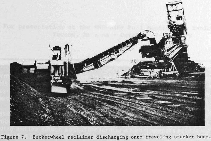
Bucket wheel reclaimers feeding conveyor systems are normally limited to applications requiring flow rates on the order of 1800-6000 metric tons/hr (2000-6600 short tons/hr) or more and involving 100% reclaim of the stockpile or, material which is too sticky to permit the use of belt conveyors in reclaim tunnels. Figure 7 shows a bucket wheel reclaimer feeding a variable height, slewing traveling stacker with a reversing conveyor on the boom. The stacker discharges the material onto the yard belt.
In some cases, the bucket wheel is mounted directly on the boom of a variable height, slewing traveling stacker. This arrangement eliminates the separate bucket wheel unit and an operator but does limit the size of stockpile that can be reclaimed and also creates the need for a very massive stacker structure to support the weight of the bucket wheel and resist the forces exerted during the operation of the bucket wheel. Applications where the use of a bucket wheel reclaimer is contemplated should be referred to the manufacturer or a consultant to gain the benefit of previous application experience.
Well designed stockpiling systems can offer significent improvements in the efficiency of mill operations through their ability to provide a uniform flow of consistent quality ore thereby maximizing mill output while reducing costs. To properly size the stockpile system, factors such as the available output flow of each processing stage as compared to the required input flow for the succeeding stage, normal maintenance procedures and emergency shutdown accumulations must be considered.
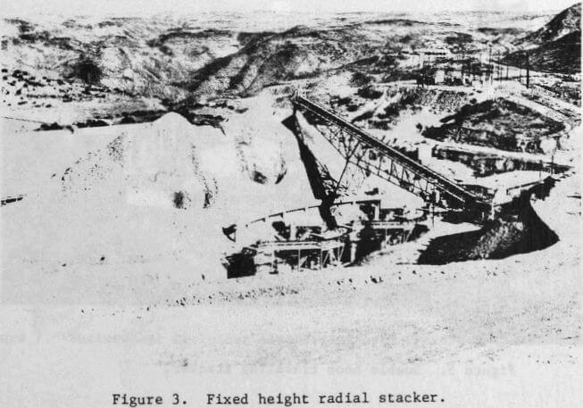
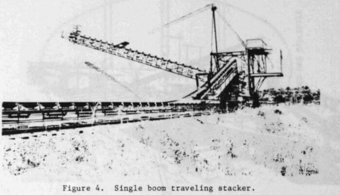
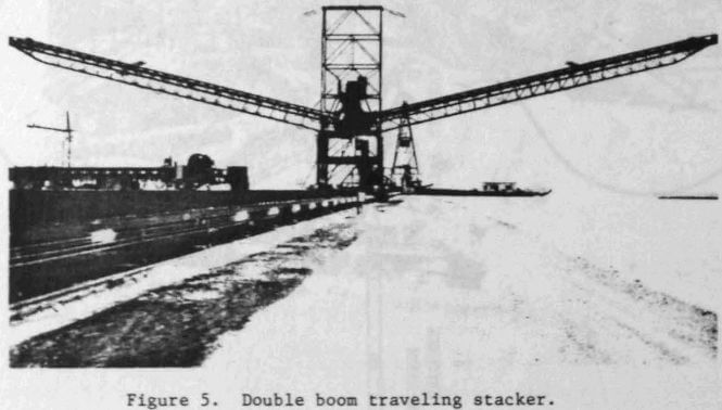
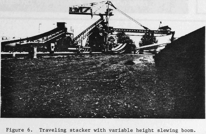
Stockpiles may be built by front end loaders or belt conveyors. The simplest stockpile configuration is a fixed stacker building a conical stockpile; however, significant cost and operational advantages are provided by alternative units such as the radial stacker and traveling stacker if the application involves blending or larger stockpile capacities. Operation of these stackers can range from manual to completely automatic. Front end loaders are limited to medium rate of flow and/or sticky material applications.
Reclaiming from stockpiles is accomplished by front end loaders, belt conveyors in reclaim tunnels or bucket wheel reclaimers feeding conveyor systems. Belt conveyors in reclaim tunnels are the most efficient reclaim device if the material to be reclaimed is free flowing. Bucket wheel reclaimers feeding conveyor systems are limited to high capacity-100% reclaim or high capacity-sticky material applications.
Careful analysis of alternative stockpiling and reclaiming arrangements with consideration given to capital costs, operating expenses, material characteristics and site limitations will provide the optimum stockpiling system.
Uniform Material Flow
Uniform material flow is the most basic requirement of a stockpile system. A primary reason for a stockpile is to smooth out the material flow from an intermittent operation to succeeding continuous operations. For example, the intermittent dumping of trucks into a primary crusher does not provide a suitable flow of material to feed an autogenous mill line directly.
The ideal arrangement from an operational standpoint is to have a stockpile prior to each stage of crushing. Such a layout provides the optimal material feed to each stage and hence, maximum output and efficiency. In order to establish the basic stockpile requirements, one must evaluate the output flow of one processing stage in relationship to the input requirements of the succeeding stage. Such things as minimum and peak output rate and duration, minimum and peak input rate and duration, normal start-up and shut-down operations and emergency shut-down accumulations must be taken into account in sizing the stockpile for each stage.
Unfortunately, few systems attain the “ideal” described above since economic and physical size restraints are often governing factors. However, compensating for this is the fact that most processes become progressively more continuous. While substantial stockpiles may be required in the primary stages, most processing schemes rapidly reach the point where a small bin or hopper is all that is required to smooth out the material flow. The desired uniformity of flow from each stage to the next must be determined by the individual evaluating the precise arrangement under consideration and the cost of attaining that uniformity must be weighed against the benefits provided. These benefits include maximum output, decreased electrical power costs per ton processed due to elimination of partial and no-load conditions, lower maintenance costs per ton due to more uniform crusher liner wear, elimination or limiting of shock loading due to variations in material flow, reduced down time for equipment servicing and in some cases, reduction in the work force required due to the greater automation possibilities with a uniform flow.
Stockpile Reclaiming Equipment and Arrangements
As indicated previously, front end loaders are usually limited to medium capacity and medium rate of flow installations. Typical reclaim rates for front end loaders are about 275-900 metric tons/hour (300-1000 short tons/ hour). Front end loaders are effectively utilized in the uranium industry for reclaiming from several smaller stockpiles of ore which come from separate sources. Front end loaders are also used when the material to be reclaimed is sticky and tends to hang up and is therefore not suitable for reclaiming with belt conveyors since it will not flow to the feeder opening.
Bulldozers are often utilized in larger stockpiling systems in order to increase the dead storage capacity. Since all of the material that is dozed into the dead storage area must be dozed back into the live storage area for reclaiming, bulldozers also function as reclaiming devices. If possible, this type of dead storage expansion should be avoided due to the expense of the double material handling involved.