Table of Contents
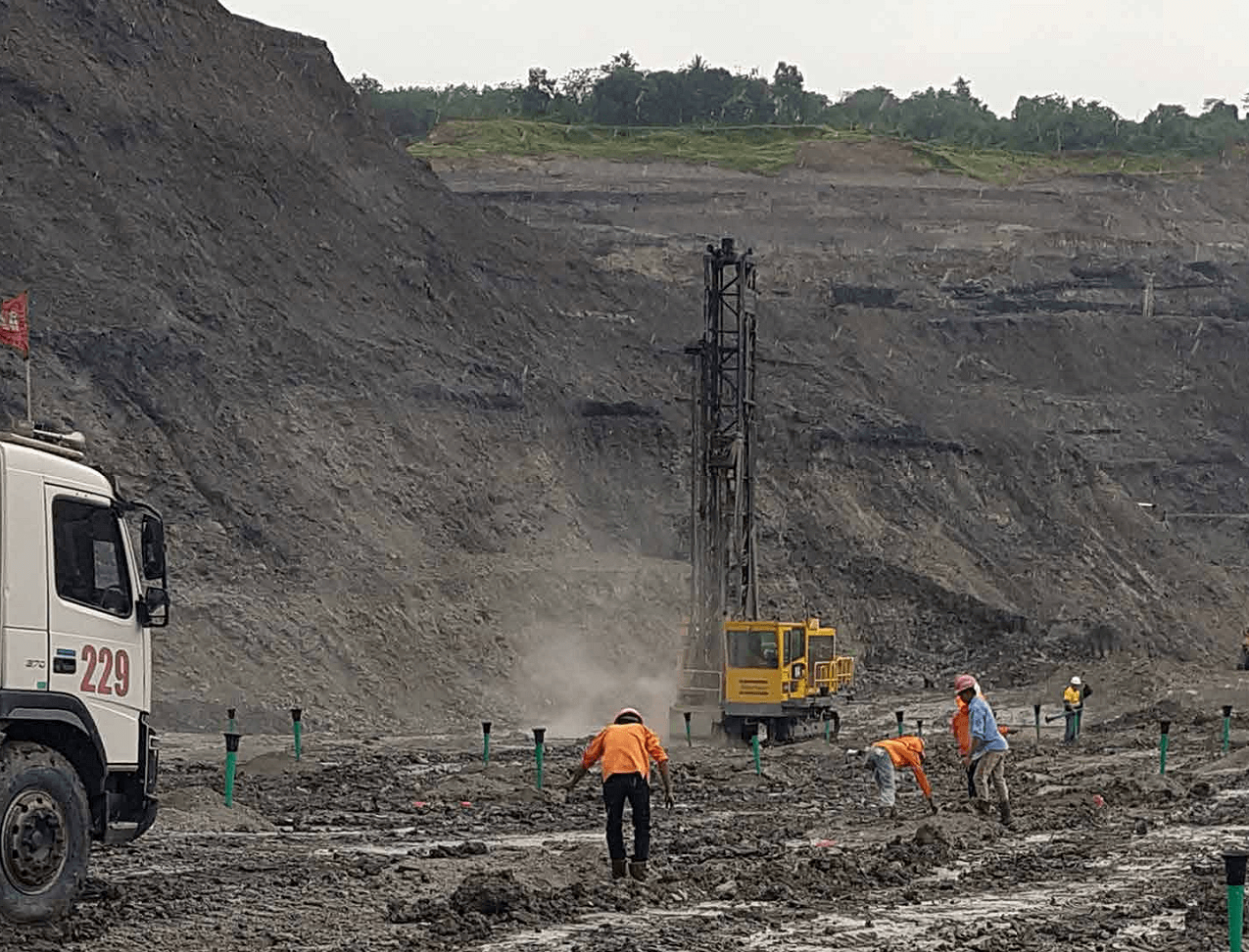
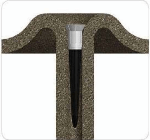
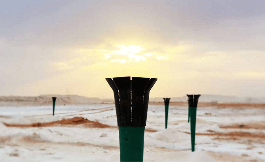
Better Air Decking using the Saver Plug, offers a reduction in fly rock, vibration, drilling costs, and the volume of explosives used in blasting. It is used across all sectors of the mining industry, including underground horizontal hole blasting.
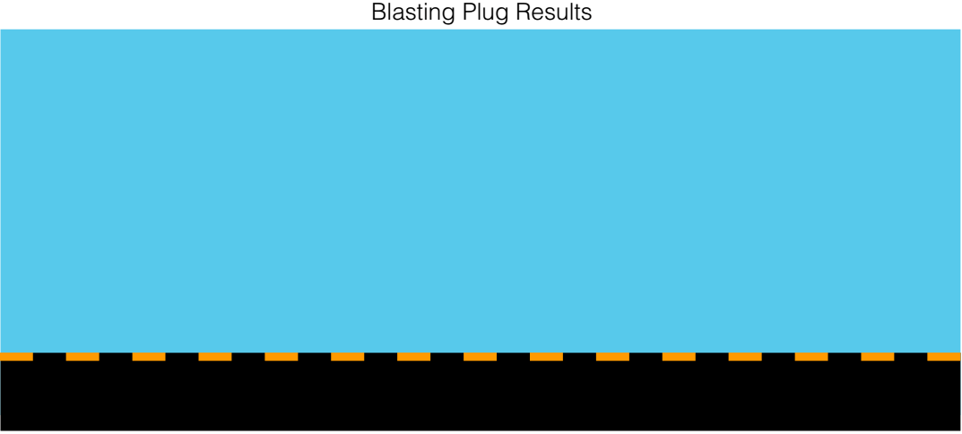
Increased fragmentation and cast percentage is achieved with the same or reduced Powder factor. All of the above could be achieved without changing the blast design or Capital expense.
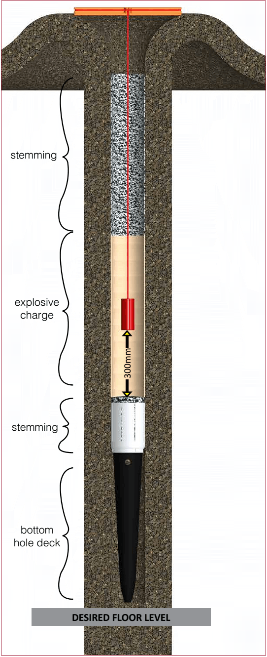
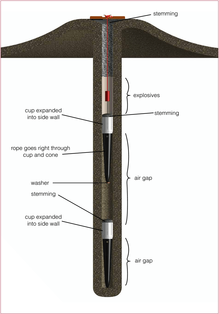
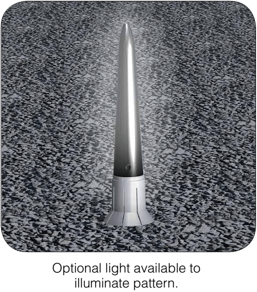
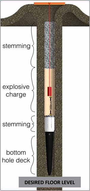
The Saver Plug system for blasting operations and casting applications. The Saver Plug methodology is made possible by the placement of a Saver Plug, along with air and mass strategically placed in a blast hole to improve blast results and therefore reducing blasting cost.
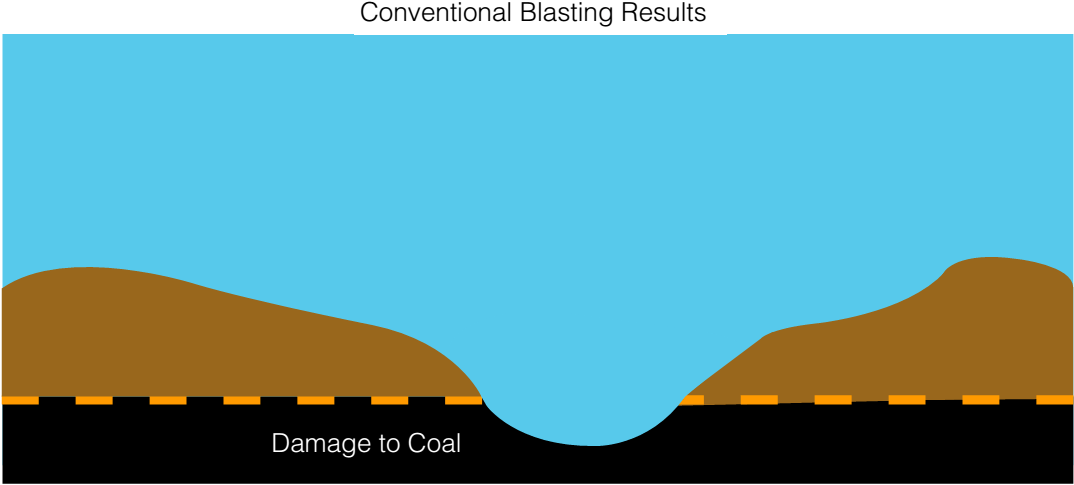
Historical results in mining applications proved a reduction of 10%-50% of explosives consumption, 75% reduction in vibration, and completely eliminating air blast and fly rock. Despite reducing explosive consumption, the fragmentation distribution remains unchanged or is actually improved in some operations, while reducing the undesirable fines content in others.
Blast energy is focused in a downward direction as a result of decking designs, increasing control. In some instances, stemming length can be reduced without increasing the danger of fly rock. The throw volume in casting application could be increased, whilst sub – drilling in some cases were reduced by 100%.
Sub-drilling reduction
The Saver Plug system is best explained in terms of pressure and / or kinetic energy at the bottom of the hole.
The path of least resistance is always taken by the shock waves when an explosive detonates in a borehole. The bottom portion of the hole in the air deck will first be subjected to a high intensity shock wave. After the initial shock wave front hits the bottom of the hole it creates a reflection and increases the pressure at that point.
On completion of the initial shock wave, a secondary impact from the explosion products adds another pulse to the bottom of the hole. The effect of the first and second combined, results in increased pressure at the bottom of the hole, up to seven times greater than the initial pressure. The increased pressure is sufficient to increase fragmentation.
The primary shock wave energy and secondary explosion products are far more efficient than a concentrated cylindrical charge, but only when the bottom hole air deck length and Saver Plug mass are properly designed for the specific field conditions and explosives system.
The Saver Plug system can be used to reduce and, in some instances, eliminate sub-grade drilling. By inserting the Saver Plug and bottom support into the bottom of the bore hole, we created a path of least resistance for the explosive energy to seek.
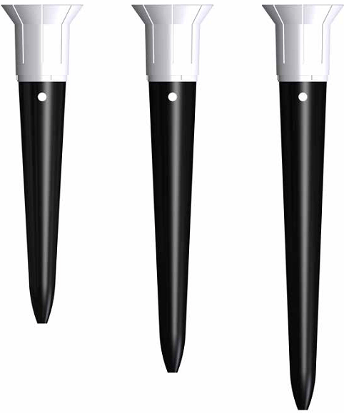
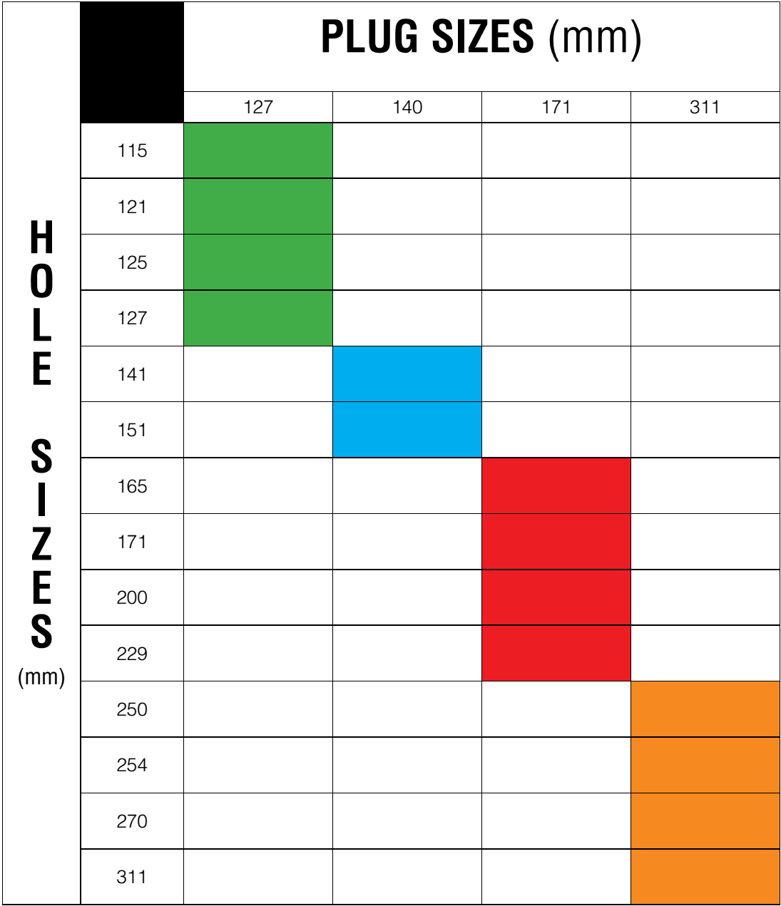
Plug Selection Chart
Benefits
- More control of the blast.
- Saver Plug is kept above mud, and keeping booster in product preventing blow outs due to booster laying in mud.
- Less vibrations are produced.
- Lower noise levels.
- Less fly rock and rifling.
- Increased high wall stability.
- Better fragmentation.
- Assists in preventing dilution of mineral and waste.
Downstream Savings
• With better fragmentation there is reduced wear on load and haul equipment.
• Loading of material is faster.
• Smaller fragmentation reduces wear in mill, faster processing times and increases through put, benefiting production.
Drilling Process
• Less Sub-drill needed.
• Less re-drills.
• Less explosives required.
• Improved pit floor conditions and less toes.
• Increases blasting frequencies.
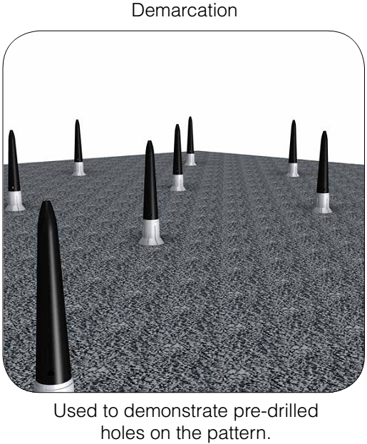
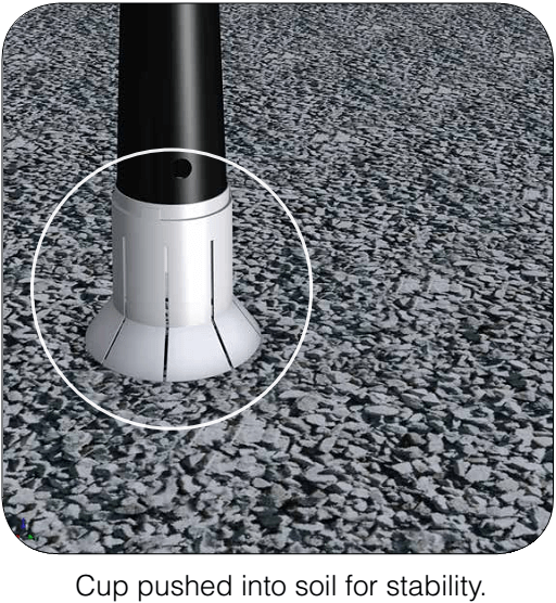
• Blasting plug can be used for demarcation.
• Blasting plug can be used to plug top of already drilled holes to prevent chippings from falling back into hole during drilling process.
Detonation Path
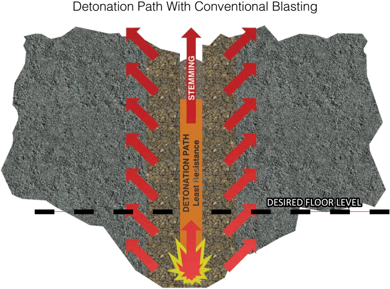
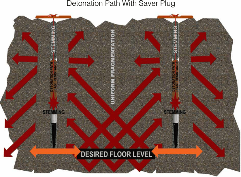
Blasting Results
Mid Hole Decking
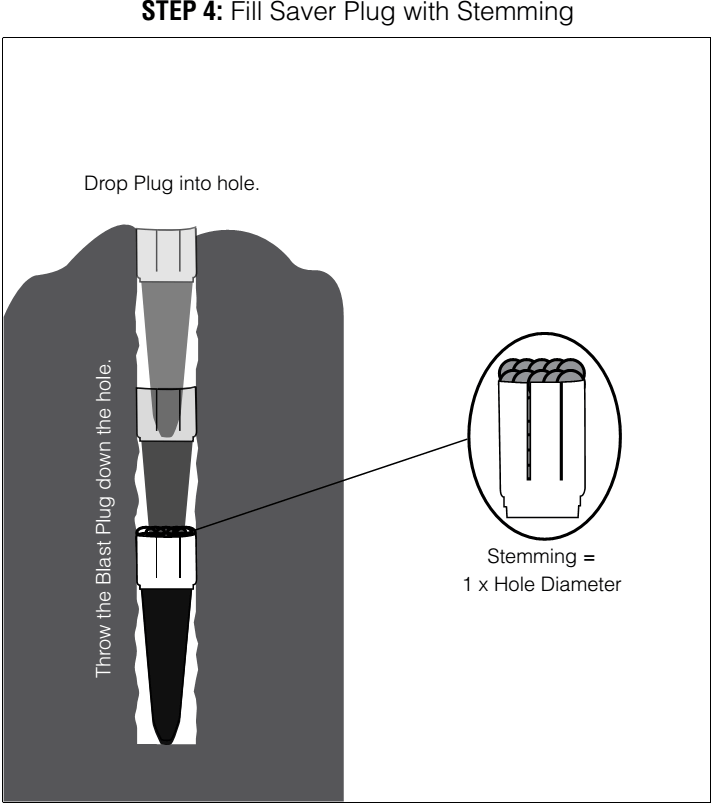
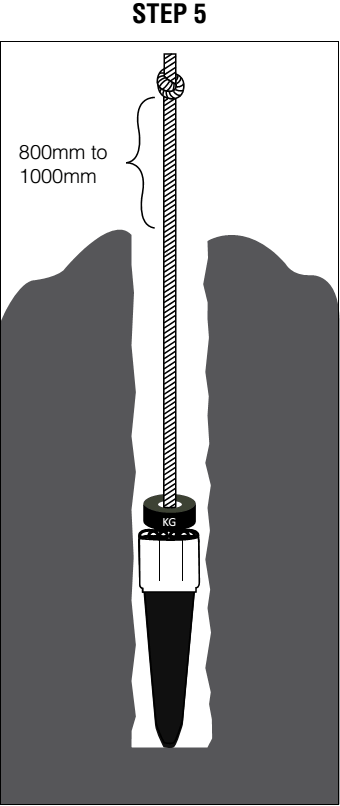
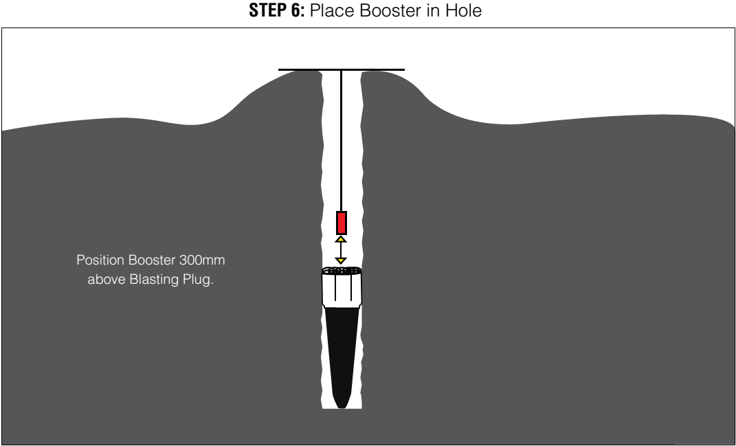
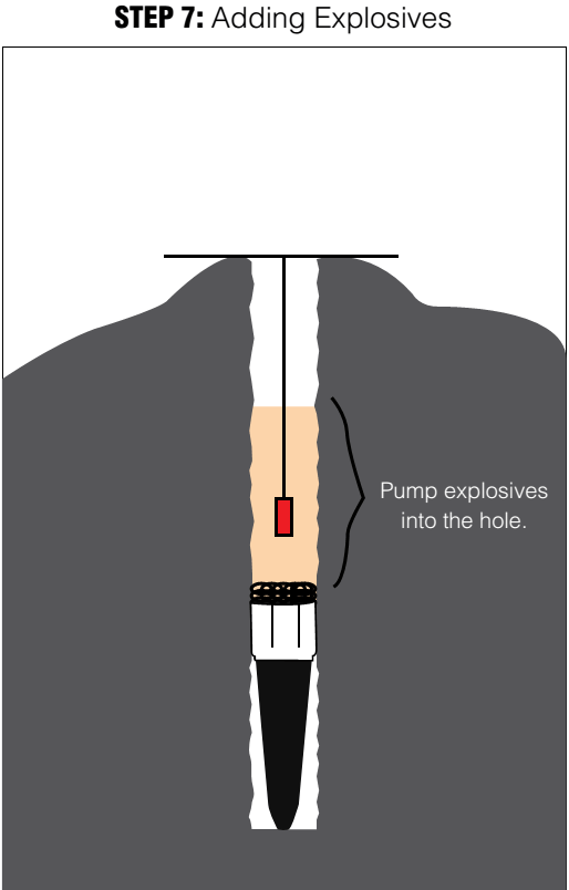
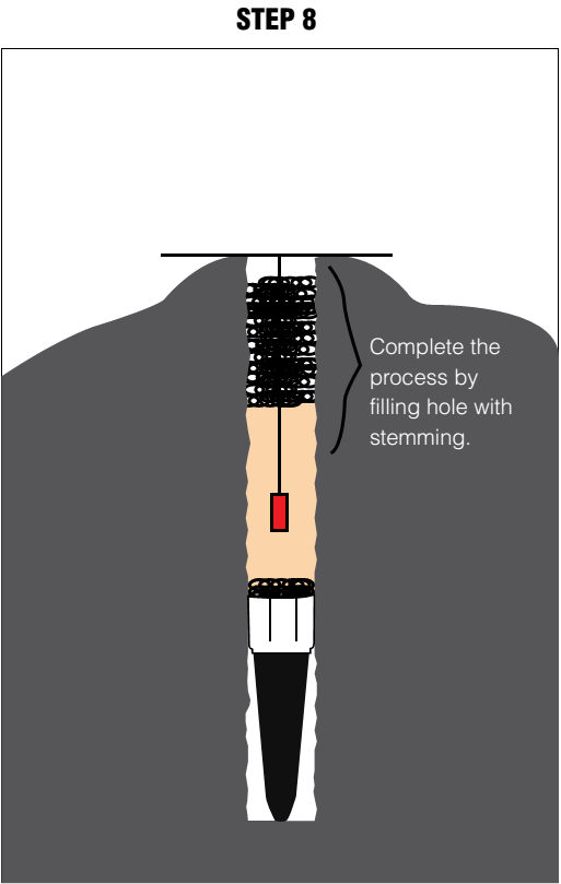
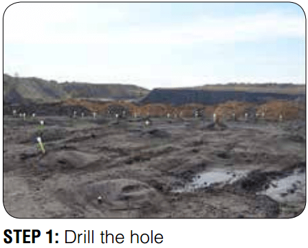
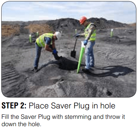
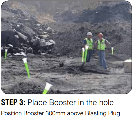
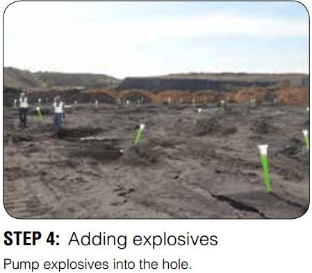
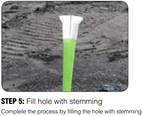
Step by Step Guide
 |
 |
 |
 |
 |
 |
 |
 |
 |
Additional Uses
CASE STUDY
Having been approached back in December 2017 by a South African based company called ‘Saver Plug’, they offered us a trial of a product which creates an ‘air-deck’ at the bottom of the blast hole, rather than the middle or the top of the column. The product was promising to:
- Improve floor level under blast as energy from explosives is directed downwards as well as upwards.
- Improve rock fragmentation.
- Create a better ‘throw’ from the free face of the blast, giving each hole improved movement between rows.
- Reduce blasting costs per hole by replacing 1m of product with the Saver Plug.
We arranged a visit for the demo at the cost of Saver Plug, and arrived on the 21st January, the original agreed amount of plugs for the trial was 150, we received 210 from him, the trial areas were planned for Thursday 26th January. Two of our most challenging areas of Pit 2, OB1 & OB2.
1st Test Area
OB1 07 Blast no 30
Holes – 85 Burden – 6m Spacing – 6m Depth – 12.1m
 |
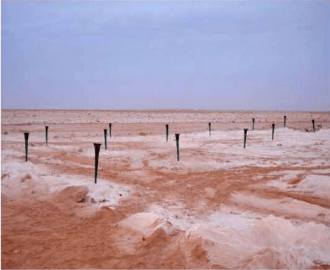 |
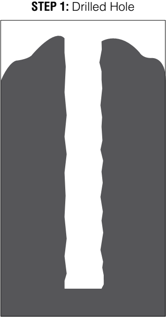
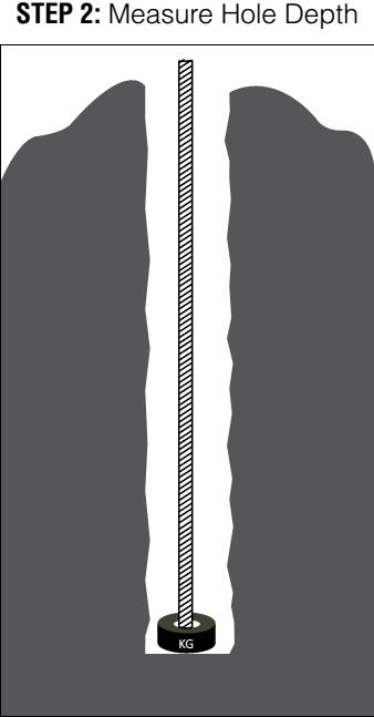
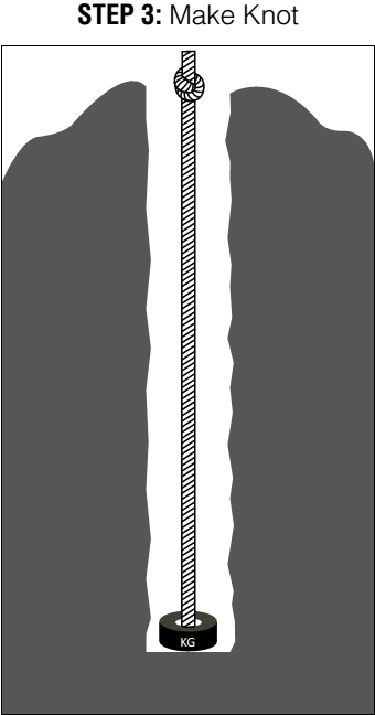
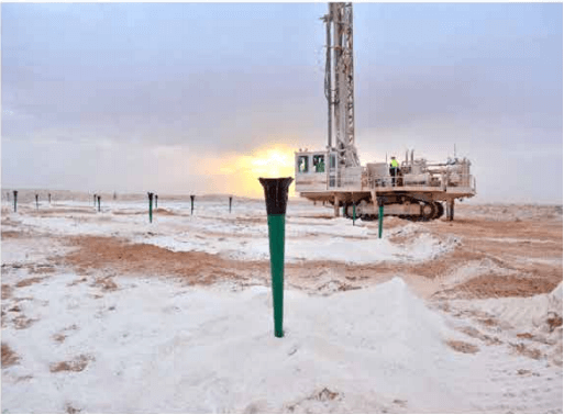
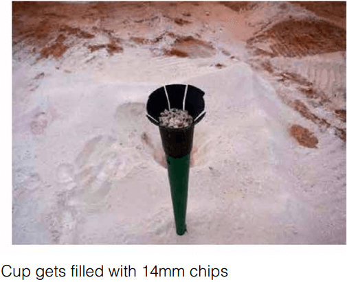
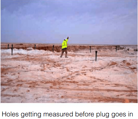
The blast area was set out with the Saver Plugs loaded with chips and set out at each hole in the planned blast. Each hole was then measured to get the depth, plug was then simply dropped into the hole, and blast hole was then re-measured to make sure the plug was at its correct/desired depth.
 |
 |
Note – not all blast holes measured as plan depth there was a variance from 0.5m – 1m in some areas post drilling.
Post measurement plugs had no problems with plugs reaching their desired depth, a very simple process.
 |
 |
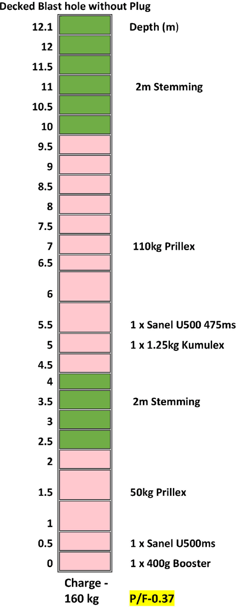
Blast was charged with no problems and the initiation sequence we used was a 42m/s control line with 67ms cutbacks providing a burden relief of 14ms/m.
Firing the blast I noticed there was a gap in the initiation sequence as highlighted in the picture below.
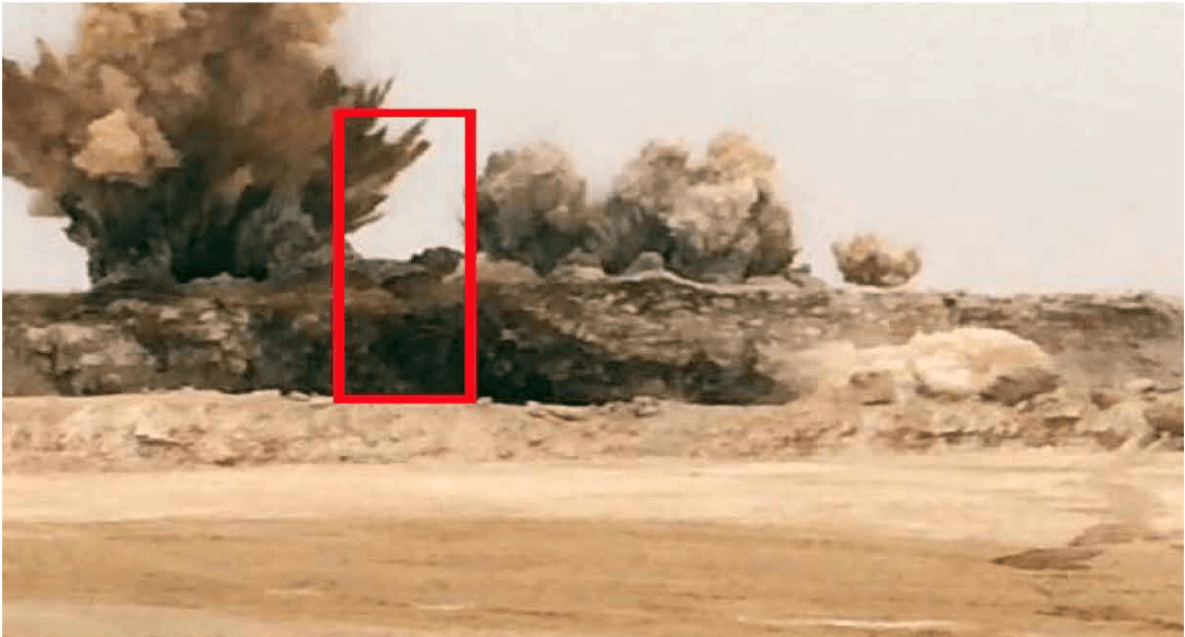
Post blast assessment of this area shown the detonators/surface connectors to have initiated, post blast pictures shown below.
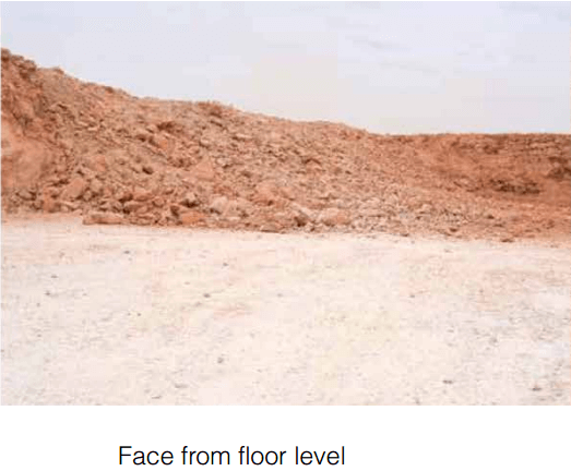 |
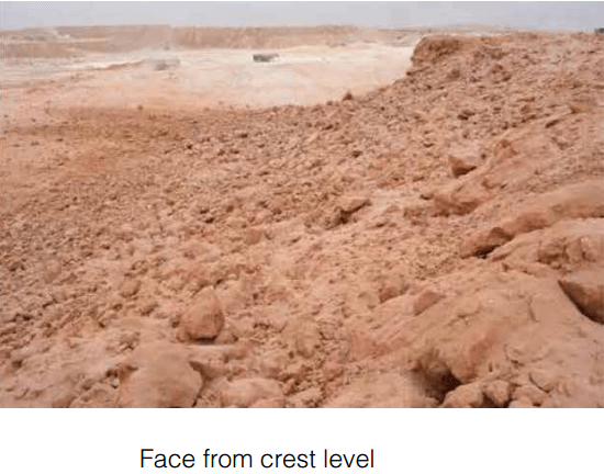 |
Post inspection the ‘throw’ from the blast looked better than previous blasts in this area, we compiled a cross section blast profile shown below.
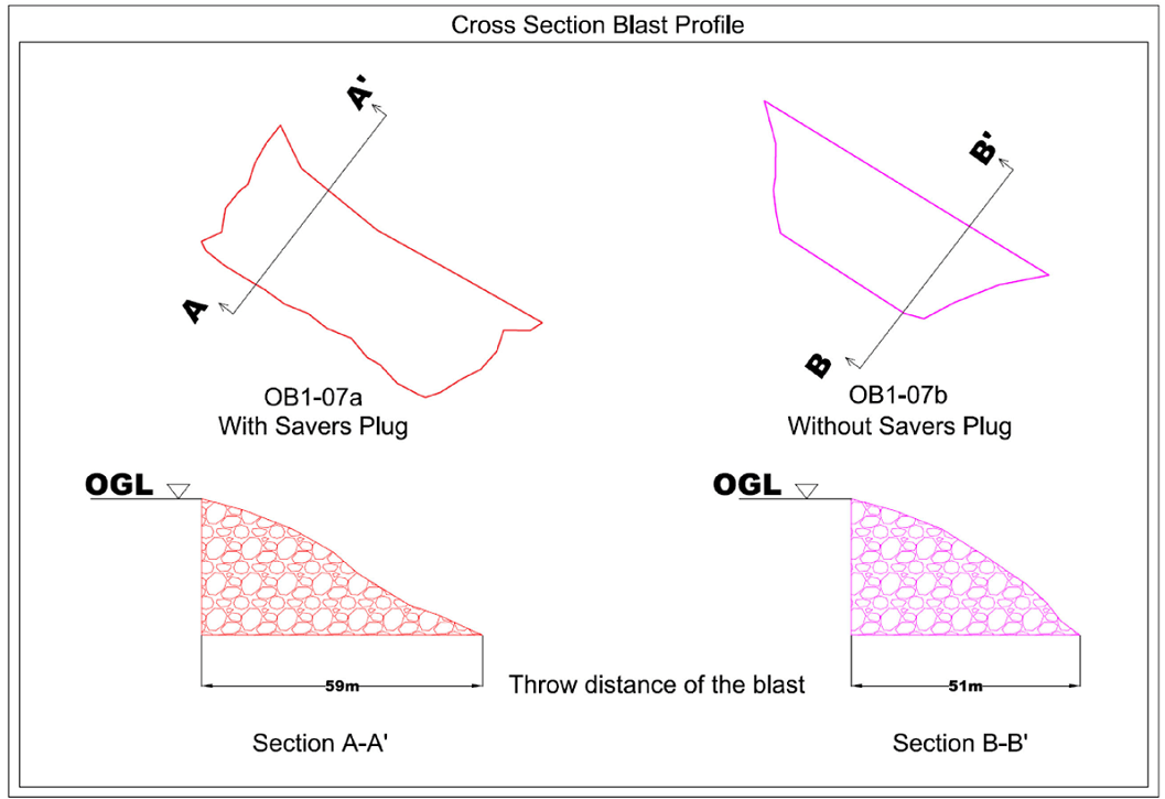
As shown in the cross section above (section A-A) the throw from the blast was 8m further with saver plug than in the cross section (section B-B) without the plug, suggesting a more “contained” blast pushing the material out from the face rather than horizontally where the energy is lost and not being used to its full potential.
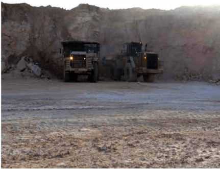 |
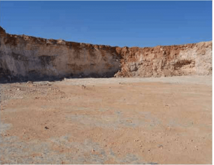 |
Area was monitored during loading, and above is the completed excavated area.
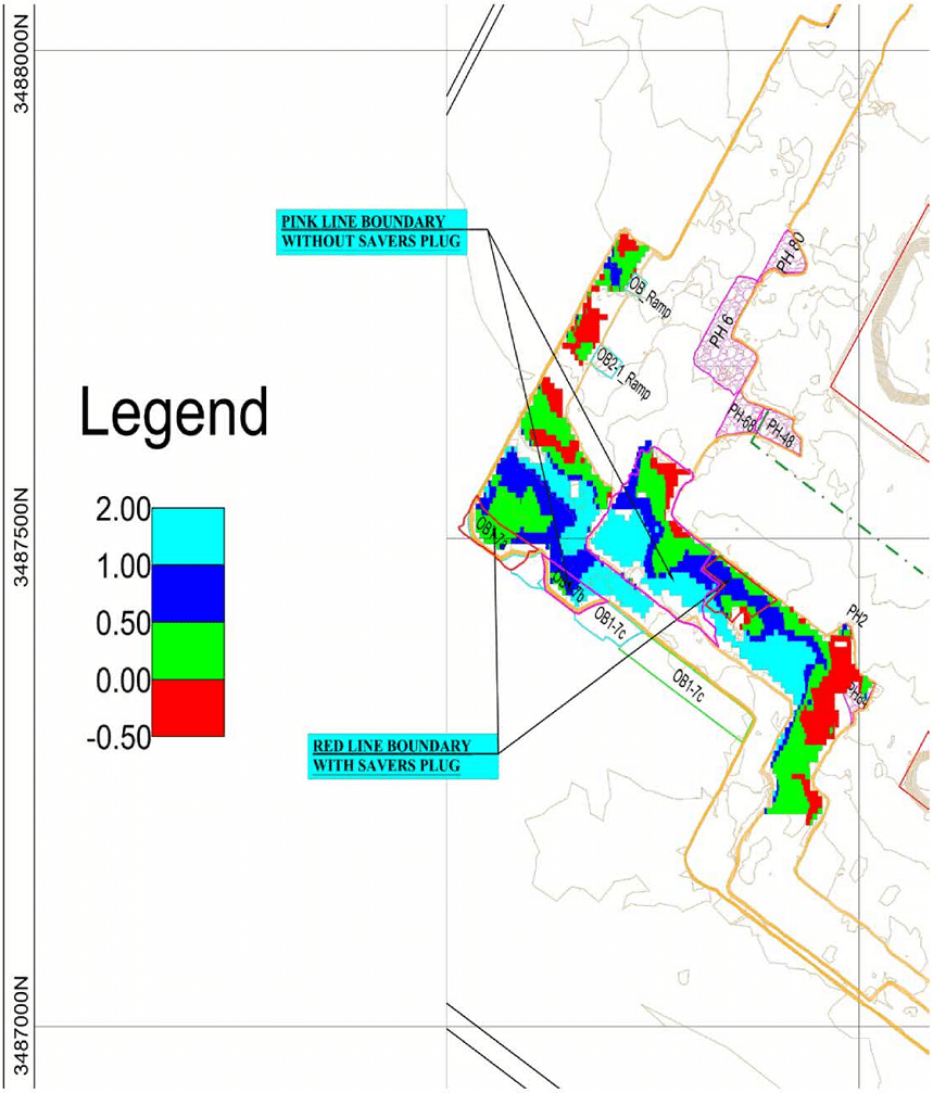
The map below shows the floor level post excavation survey at 0.0m – 0.5m at the floors highest point, which in fairness was the depth discrepancy found in some holes based against desired plan depth found during the measuring process before the plugs were inserted into the holes.
2nd Test Area
OB2 02 Blast no 29
Holes – 150 Burden – 5m Spacing – 5m Depth – 6m
This blast was initiated along with OB1 7 the problem with this area of OB2 is the very hard band of rock that sits on the phosphate roof and with a ‘medium-soft’ density rock on top of this band this creates an easy escape for any explosives, for this reason we increased the stemming level, this is implemented is this area to confine the explosive in the hard band, but there is very little room for error in this area, any drill deviation from plan depth, geological changes in the soft rock above or loading issues show up very quickly in this area. For these reasons I thought this would also be a good area to try the saver plug.
The blast was set up with 150 holes drilled and 123 saver plugs were used in the area the area where the 123 plugs were used is highlighted in the Blast Floor Scenario along with OB1 7 on the previous page.
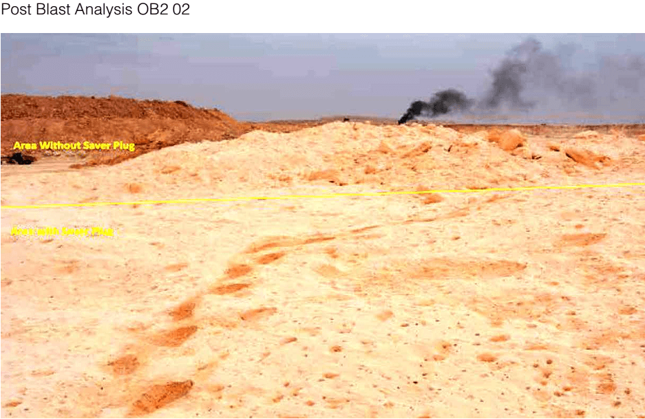
As you can see from the picture above the area where the plug was used confined the explosives more than the area without the plugs, also the fragmentation was improved. Referring again to the Blast Floor Scenario the results post excavation show the area where the plugs were used showed there are high spots remaining in the area but are no higher than 1.0m. The area outside this perimeter has high areas remaining of up to 2m.
Post Blast Analysis OB2 02 (cont.)
Due to the density of the hard band above the phosphate (band creating high spots) this area of OB2 – Phosphate should really be drilled at 4m x 4m again designed with an increased stemming level for explosive containment, but due to current drilling capacity this is not possible, therefore I think the plug would give us a ‘helping hand’ in this problematic area.
Regarding the cost analysis, the table we created is listed below, all the required information was gathered and we based the costing on a blast hole 10m in depth, burden 6m & spacing 6m with 3m of stemming and a 7m column charge. As the cost of the saver plug are in USD, the figures in our cost analysis chart are inputted also in USD, which works out at a saving of $8.44 per hole which equates to 31.66sar, based on the pattern of 100 holes below this would save 3166sar.
Conclusion
As in any business it is good to save money, but it is also about the products practical results, where if we were to introduce the product savings can also be made elsewhere by means of higher bcm due to enhanced rock fragmentation & better floor levels for trucks.
Main areas where these plugs could be used is in primary Overburden areas (OB1) IN Pit 3 there are cavities in the rock recently they have been on the bottom (<0.8m) where we have been unable to charge creating an uneven floor, but if we used the plugs in this area it would give us an opportunity to get the plug to work for us, by creating a charge going into the floor, creating a more consistent floor level.
OB1 Pit 2 we have irregular cavities/ soft areas in the rock, the plug can also be used to help ‘deck’ through these problem areas, providing an accurate solid base for the column charge, again as mentioned previously the plugs main purpose would be to help us provide a consistent & desirable floor level during blasting in order to make production as hassle free as possible.
If used properly and results closely monitored I think the Saver Plug would be a viable option to trial in Overburden for 1 month.
Contact Clayton Hitchcock
Development of Fragmentation System Design (FSD)
The principal objective of developing such an expert system is to integrate the knowledge of a mine designing and planning engineer with the advanced computer technology. The product, the expert system “FSD,” that results from this integration of knowledge, experience and technology helps and guides the end-user in obtaining both technical details as well as economic analysis of the suitable fragmentation system for any given surface mine.
Expert System Shell
The expert system shell that has been used to develop “FSD” is known as Knowledge Engineering System (Unisys 1986). The FSD knowledge base is a file containing the facts and the heuristics. When the end-user uses FSD, the inference engine (PS based) uses the knowledge provided by the knowledge base author (programmer) and information obtained from the end-user to obtain solutions to problems.
FSD Knowledge Base Sections
The knowledge base is composed of sections. The following sections appear in this production rules based expert system: constants, text, attributes, rules, and actions. But, the sections of fundamental importance to a knowledge base are: attributes, rules, and actions.
The attributes section declares attributes, which are the primary location for holding specific information. At run time, attributes hold values provided by the end-user or inferred by the inference engine. Input attributes are used to form questions asked to the end-user and inferred attributes form the basis of the expert advice to the end-user.
In FSD, some of the input attributes are diameter of the blasthole, strain energy factor of the rock, and average density of explosives to be used in blasting. Since the values of these are not going to be inferred by the system they are to be provided to the knowledge base by the end user during the interactive session with the expert system. FSD forms suitable questions to obtain values for each of the input attributes and these questions are asked to the end-user in a sequential manner while providing explanations and justifications requested by the user at each step of the session. For an example, burden is an inferred attribute in FSD and depends on total charge weight per hole and blastability factor. As soon as the system realizes that it needs to know the blastability factor before it can determine burden, it treats blastability factor as an inferred attribute and tries to find its value. But the blastability factor depends on the train energy factor and the diameter of blasthole. This interdependency leads to the determination of strain energy factor and the diameter of blasthole by the system in order to find the blastability factor. Strain energy factor does not depend on any other attribute and thus the system recognizes this as an input attribute and forms a question for the end-user to obtain the value. At this point, if the user has questions regarding the attribute, he/she may ask FSD to explain or justify the question.
The rules section defines one or more rules. Rules are knowledge sources for attributes. The PS inference engine uses rules in its backward chaining technique to infer values for attributes. A rule helps in inferring the value(s) of one or more attribute(s). For example, production of a ripper per hour of operation is most likely to be 1050 cubic yards only if the ripper type is Caterpillar D9L Single Shank ripper and the compression wave velocity of the rock is between 5000 and 6000 foot per second. In this example, the inferred attribute is the production per hour and it depends on the ripper type and the compression wave velocity of the rock. The inference engine recognizes the interdependent relationships and, if it needs to obtain the value for production per hour, it would work backward and obtain values for ripper type and the velocity either from the information available to the system at that instant of time or from the end-user by forming suitable questions.
The actions section is used to issue the instructions that control FSD and conduct the dialogue between the end-user and the expert system (FSD). Commands in the actions section display messages, prompt for information, and set goal attributes for the inference engine. The commands are normally executed in the order that they appear; however, some commands allow the end-user to control the order. The actions section specifies the overall sequence of events that occur when running FSD.
Knowledge Representation
Domain knowledge consists of facts about the domain and relationships between these facts. In FSD, an attribute represents some piece of knowledge of fragmentation system design. The attributes section of the knowledge base contains these pieces of knowledge. One of the most important aspects of the knowledge representation is to appropriately relate attributes and knowledge sources through the structure of the knowledge base, so that known information is used to infer attribute values and solve the problem addressed by FSD. For an example, ripper production (unknown and is to be inferred) depends on the known information such as ripper type and compression wave velocity of the rock. The concept of attribute dependency leads to the development of the attribute hierarchy of FSD. Figure 1 represents the attribute hierarchy of the system. The hierarchy shows the knowledge of FSD in a conceptual way by relating attributes in the domain. At the top of the hierarchy is the goal of the system: the attribute representing the solution to the problem that FSD is addressing. The goal attribute value is inferred from attribute(s) below it in the hierarchy. The bottom of the hierarchy consists of input attributes whose values are provided by the end-user since these values can not be inferred from other attributes.

