Our subject is “CLASSIC or Not so Advanced but yet Fundamental Flotation Circuit Process Control” Some of you may be familiar with the process; to others it remains a mysterious scheme. To you all I wish to emphasize one point, i. e., flotation is still now more of a science VS art. Our scientific data has been made available from thousands of tests and the carefully kept records of operating mills in mining districts the world over.
In dealing with this subject and outlining the means by which an operator maintains control, we will first go back a few years and briefly describe some of the more prominent mistakes made in the early years of flotation.
It was my good fortune to spend three years, shortly after graduation, with a large copper company in the west where one of the first fine grinding and all flotation plants was designed and built. As is often the case with large corporations, once the officers decide to appropriate the money for a major increase or alteration, the actual design and construction is then completed in a great rush. At the copper property we are reviewing, test work, design, and construction were certainly rushed, but even if this had not been true, I doubt whether many of the mistakes would have been rectified before installation.
As I recall the campaign, great stress was laid on reagent testing. At that time xanthate was practically unknown. Tar oils, creosote, etc., were the principal collectors known. Very little attention was paid to mixing ores, method of feeding mills, control of densities, etc. Finally, when the concentrating operation began, all technical direction was centered on the actual operation of the flotation cells, and the feeding of reagents. We were working, and continued to work for many months, at the wrong end of the mill. Flotation operators were the highest paid men on shift. The grinding mills were operated in a very haphazard manner. Feeders held up many times a shift, classifiers overloaded and kicked out, or were running practically empty. The net result of this system was that control of flotation was impossible. Since that mill went into production great improvements in flotation plant control have taken place. In order of importance I would list them as follows:
- Improved bin and ore feeding arrangements allowing grinding plants to operate continuously and steadily on a uniform feed. This uniformity of feed is governed, of course, by the character of the orebody, bin storage available, etc.
- Mechanical improvements to feeding, grinding, classifying, pumping, and flotation equipment.
- Definite density control at all points in the circuit, largely due to 1 and 2.
- Chemical collectors, reagents, and improved reagent feeders.
- Froth Flotation Rule of Thumb.
Routine Control in a Modern Flotation Plant
We will now study control in a modern flotation plant. First, we will assume that before this plant was built, a thorough ore-testing campaign had been completed and detailed knowledge obtained of ore characteristics. Economical grinding limit had been determined and a suitable reagent balance decided.
Then, with the plant running, the operator’s job is to maintain as nearly as possible the conditions which were found in testing to be the most suitable for the ore in question. He maintains conditions by a routine system of tonnage and density samples, accurate measuring of reagents, sampling of products, and close observation and recording of results.
Pilot tables may be used to advantage on tailings or at any point in the circuit to aid operators. Less common methods of control include dispersion testing, rapid assaying of products, etc. The factors listed as follows all have a bearing on the successful operation of a flotation plant:
Mill Feed to Flotation
Tonnage Screen analysis.
Grinding Circuit Controls
Percent circulating load, mill discharge and classifier overflow densities.

Flotation Circuit Controls
- Flotation Feed Density, Alkalinity, Temperature.
- Tailings Density, Alkalinity.
Flotation Reagents
Mixing, feeding arrangements.
Points of Control
The crushing plant is the first point at which control must be exercised. Almost without exception, fine crushers are operated in closed circuit with screens so that a positive size of feed is maintained at all times.
The second point of control, and one of the most important, is in the mill storage bin. Wherever plant layout will permit, we mix the ore by trippers, shuttle conveyors, or other devices. Likewise, we discharge ore from the bins by vibrating feeders, constant- weight feeders, etc., at a uniform rate.
We have now arrived at the wet grinding mill; SAG mill, ball mill, rod mill, tube mill, as the case may be. Feed is closely sized and being fed at a uniform rate. The next point to check is the water feed to the grinding unit. Mills must be run to suit flotation, not to secure optimum grinding results. In our model plant we have already determined by test or experience the most desirable densities to maintain in the mill and classifier, the best circulating load to carry, etc. Under absolutely ideal conditions the grinding plant should be practically automatic. However, it is impossible to maintain ideal conditions, hence the operators must constantly check and record.
With a uniform feed as to mesh size and density being delivered to the flotation plant, the operator in that section has one primary concern to make sure his reagents are fed at a constant rate, and to maintain constant conditions of alkalinity, etc.
Too much importance cannot be placed on the control exercised by the mill shift operators. Experienced operators in charge of the grinding and flotation floors, by careful observation and strict adherence to plant rules may be largely responsible for increased efficiency in the matter of tonnage treated, percentage recovery, or both.
Methods Used in Determining Densities, Alkalinities, Etc.
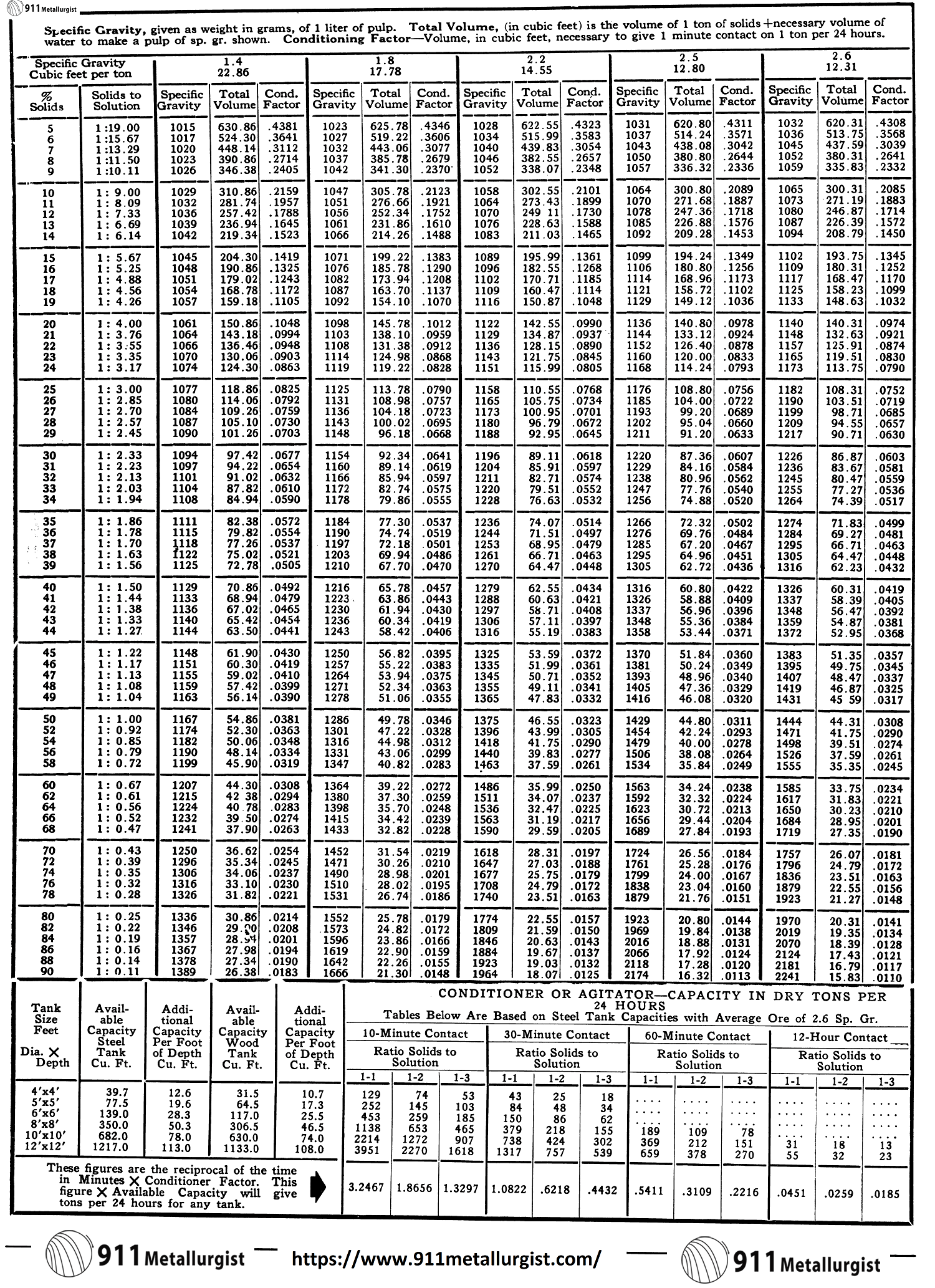
Density Calculations
A pulp sample of approximately 1,000 cc. is cut out of the circuit and weighed in the specific gravity can on a set of gram scales. This sample must always be taken with a container of known weight and volume. One of 1,000 cc. is generally used and the scale adjusted to balance the weight of the dry, empty container.
Specific Gravity of Pulp = Weight of known volume of pulp/Weight of equal volume of water = Weight of pulp/Volume of pulp
The percent solids corresponding to the specific gravity of the pulp is then read directly from a set of tables. A direct reading solids table is of no use except for the particular part of the mill where the solids sample is taken. This is because of the difference in specific gravity of the solids at different points in the circuit. The following formula shows the manner in which a direct solids table is worked out for the grinding circuit:
Percent dry solids = d/p x 100 (p-1)/(d-1)
p—Specific gravity of pulp and is determined as above.
d—Specific gravity of dry solids.
This may be calculated by determining the weight of a feed sample and the volume of water displaced by the same. By taking the average of a number of tests,
d = weight of ore/volume of ore
The table is made up by substituting a figure for the percent solids and calculating the specific gravity of the pulp. The final table should show the weight of pulp for each one percent of dry solids covering the range within which the “density” of the pulp must be held. This table is used to check the percentage of solids in the mill discharge and the flotation feed.
Flotation pH Control & Alkalinity Titration
When ore is ground to a pulp with water, the pulp is usually made alkaline by the addition of either lime or soda ash. Control of the alkalinity is highly important. If for some reason you do not have a simple pH Meter… here is an old fashion alternative.
The lime may be used in the form of quicklime (CaO), or hydrated lime (Ca(OH)2). Lime added as quicklime immediately becomes hydrated lime when mixed with water. Soda ash is impure sodium carbonate (Na2CO3).
An ore pulp is made alkaline for any or all of three reasons:
- To assist in settling the ore after grinding when it is necessary to remove part of the water by thickening before further treatment.
- In flotation to give the alkalinity necessary for most modern flotation reagents and for the chemical effects on both the sulphide and gangue minerals in the pulp, and
- In cyanidation, to give “protective” alkalinity.
In flotation, soda ash is frequently used in one part of the circuit and lime in another. It is therefore necessary to be able to tell how much alkalinity is present in a pulp and in what form.
The control of the alkalinity of a pulp is usually based on what is known as the “free” alkalinity of the pulp water. Part of the lime or soda ash added to a pulp is consumed by the minerals in the pulp; the remainder is “free,” that is, it has not been consumed. It is important in either flotation or cyanidation to keep a certain amount of “free” alkali in the pulp at all times.
“Titration” is the name given to the method of determining the alkalinity of the pulp water. The principle of the method is that the alkali of the pulp water will combine with an acid. A ‘‘standard” acid solution is provided for this purpose. The measure of the amount of alkali present is the amount of acid used. To show just when this exact amount of acid has been added to the pulp water sample, an “indicator” is used which changes color at that point. The strength of the standard acid is based on the volume of pulp water that is to be taken and the amount of alkali to which a given volume of the acid is equal. The result of the titration is usually given as pounds of the alkali present per ton of pulp water.
A sample of pulp is allowed to settle, the pulp water is then poured off and filtered. The volume of pulp water used for titration is ordinarily measured with a pipette but in the case of large volumes, a 100 cc. graduate is used in place of the pipette.
Indicator solutions are weak solutions of chemicals which show by a color change that sufficient acid has been added to the pulp water to combine with all the alkali present. A few drops of the indicator are added to the pulp water to be titrated. The “Standard” acid solution is run slowly from a burette into the measured volume of pulp water in a beaker. Acid is added until a color change indicates that a sufficient amount has been added to combine with all the alkali present.
The usual method of determining free lime alkalinity of a mill pulp is to titrate a given volume of the pulp water with a standard solution of either sulphuric or oxalic acid, using phenolthalein as an indicator. If the pulp water is alkaline, the indicator gives it a red color and when sufficient acid has been added to combine with all the lime present, the red color disappears.
When soda ash is used to maintain alkalinity, methyl orange is used as the indicator. Methyl orange gives the water a yellowish color that changes to a pinkish red when sufficient acid has been added to combine with all the soda ash present.
When both soda ash and lime are present in the water, the mixed alkalinity is given by titration with methyl orange. Call this “B.” Titration with phenolthalein gives all the lime plus one-half of the sodium carbonate “A”. If we multiply this titration by two, we will have twice the lime plus all the carbonate. Then subtracting the former titration “B” from this, we will have the amount of the lime present. The amount of the lime present when subtracted from “B”, the overall mixed alkalinity, gives all the sodium carbonate present.

TO MAKE A STANDARD SOLUTION OF SULPHURIC ACID
Pulp to be maintained at 1-pound per ton. Use 10 cc. of pulp water for titration. Fifty-six parts by weight of lime combined with 98.1 parts of the sulphuric acid. Acid 96.0% pure and specific gravity 1.84. Volume of sulphuric acid to be made up to 1,000 cc.:
Lb. Lime in solution/2000 x No. of cc. used X 98.1/56 x 1/SG of acid
pH Determinations
In some mills, alkalinity is determined by pH indicators. A sample of the pulp water is filtered and a small tube filled with this water up to a mark. A measured amount of indicator is added and the contents of the tube shaken up. The color of the solution in the tube is then compared with that of a series of standard tubes of various shades of the same color. The figure on the tube that most nearly matches the sample gives the “pH” reading. Each indicator covers only a certain range of readings and a different set of standard tubes are provided for each indicator.
Flotation Reagent Mixing and Measuring
In making a solution of a given strength, we consider the weight of the substance to be dissolved in relation to the volume of the completed solution. To make a 10% solution, we dissolve 10 grams of the substance in enough of the solvent to make the final volume 100 cc. A true 10% solution will not be obtained by dissolving 10 grams of a substance in 100 cc. of water.
In making a solution of copper sulphate of a certain specified percentage strength, allowance must be made for the water of crystallization. In making up a mill solution, take the copper sulphate as being in 100-pound packages. The weight of crystals is multiplied by 159.63/249.71 to get the weight of actual copper sulphate, 100 x 159.63/249.71 = 63.93 actual pounds. From a handbook we find that a 10% solution of copper sulphate contains 0.9238 pounds to the gallon. Therefore the number of gallons from a 100-pound package of crystals= 63.93/0.9238 or 69.2 gallons. Crystals dissolved in water and volume of water brought up to this amount. The number of inches each 100-pounds of copper sulphate solution will occupy in a tank is determined and the intervals marked off on a measuring stick.
The amount of liquid reagent to be fed is usually calculated on a basis of pounds of reagent per ton of original feed in the pulp. Measurement from the feeders is made in cc. per minute so that it is necessary to convert pounds per ton into cc. per minute. In the case of a liquid fed in its natural state, the weight of a definite volume can be determined. The total weight required for the dry tonnage is calculated and then changed to volume and to cc. per minute fed from the feeders.
When a reagent being fed is a chemical in solution, the number of cc. per minute will be affected by the percentage strength of the solution.
Take the case of a 10% solution of copper sulphate fed at a certain number of pounds per ton.
- Total number of pounds per 24 hours is determined.
- Handbook gives weight per gallon of a 10% solution of copper sulphate.
- Total gallons are calculated, converted into cc., and then to cc. per minute from the feeders.
In feeding dry reagents, the pounds per ton to be fed are converted into grams per minute fed from the feeders. The amount fed can be measured by catching the discharge from the feeder for a certain time and weighing the contents of the container. This weight is usually in grams.
Tonnage & Flowrate Measurements
Tonnage measurements in a mill are necessary for two purposes:
- To determine the tonnage being treated.
- To adjust the amounts of the various reagents added to the pulp.
Where only a small daily tonnage is being treated, if the belt feeding the mill is conveniently arranged, the ore can be caught directly in a box for a definite period and then weighed direct. When the feed rate is high, or when the ore cannot be caught directly off the end of a belt, the feed rate is usually found by weighing a measured length on the belt. The length of the belt is first measured and then the speed of the belt is determined. A section of five feet or so is measured off on the belt and the feed is carefully scraped into a container and weighed. The time and weight figures obtained are ready to be used in the calculation of dry tonnage after the weight has been corrected for moisture. The usual procedure is to take a number of moisture samples on the feed and thus arrive at an average figure for the moisture content.
To measure the wet pulp in any part of a mill circuit, the pulp is caught in a drum for a measured period of time. A sample is cut in the specific gravity can at the same time and after the specific gravity of the pulp has been determined, the sample is dried and weighed to obtain a figure on the percent solids in the pulp.
Volume of the drum =3.1416 r²h (cu. ft.). Therefore:
Volume X 3600/Time in seconds to fill drum Number of cubic feet of pulp per hour.
Dry tons of solids = 3.1416 r²h x 3600 x 62.4 x Sp. Gr. Pulp x %solids/Time to fill drum x 2000
As long as the same drum is used, the volume is constant and it is possible to calculate a factor so that it is not necessary to work out all the foregoing formula every time a pulp measurement is taken. Such a factor is shown:
3.1416 r²h x 3600 x 62.4/2000
Dry tons per hour = Factor X SG of Pulp X %Solids in Pulp/Time in seconds to fill drum

Laboratory Flotation Testing & Research
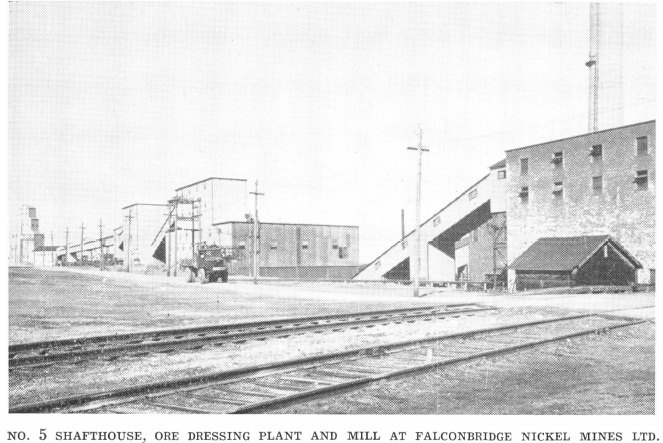
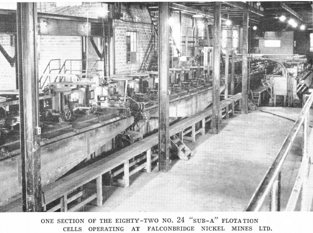
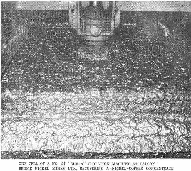
It may seem from the foregoing, that once a flotation plant is operating smoothly, in flotation, control is entirely a routine matter and that a mill superintendent would be engaged in mechanical adjustments and repairs almost entirely. This might be the case if mines continued to deliver similar ores over a period of years. Some mines do, but many do not. Ore bodies change with depth, or at their extremities. Almost without exception, ores from the same mine vary over a long period as to grade, mineral association, or grain size. Hence the metallurgist or research man will always have his place in the mill. A mill superintendent must be constantly checking ore characteristics, testing new reagents, investigating new machines. I have in mind two properties with which I am particularly familiar: The Sherritt Gordon in Northern Manitoba, and Falconbridge Nickel. The Sherritt ore is a mixture of copper, zinc, and iron sulphides, very amenable to flotation concentration. In the first year of operation, ore from the west ore-body alone was treated. This ore graded 3% to 4% Cu, and approximately 2% Zn. Very little difficulty was encountered in making a good grade copper concentrate with low zinc content. Since the property resumed production, ore from the eastern ore- body has been opened up. This carries low copper, higher zinc values and has made it necessary to make minor changes in the mill flowsheet and reagent balance.
While we are not agreed yet to the changes necessary in our treatment plant to take care of this somewhat different ore, we are engaged at present in research work to this end.
I have mentioned these examples to show what happens at an operating mine. A mill staff must be constantly testing ores and studying new methods.
What is the nature of testing or control other than routine? As newer sections of a mine are opened, tests are run to see whether the ore from that section responds to the regular mill treatment. Sizing tests are run on various products from testing to determine whether the minerals grind approximately the same. They may slime more readily.
Microscopes, infrasizers and superpanners are becoming common tools in mills. This equipment, used in conjunction with new mineral staining methods, is proving of great assistance in laboratory investigations.
Source: This article is a reproduction of an excerpt of “In the Public Domain” documents held in 911Metallurgy Corp’s private library.

