Heap leaching of gold and silver ores is conducted at approximately 120 mines worldwide. Heap leaching is one of several alternative process methods for treating precious metal ores, and is selected primarily to take advantage of its low capital cost relative to other methods. Thirty-seven different heap leach operations with a total production of 198 tonnes of gold per year (6,150,000 ounces/yr.) were surveyed to determine operating practice. These operations together produce 7.4% of the world’s gold. When mines not surveyed are taken into account, it is likely that heap leaching produces 12% of the world’s gold. Heap leaching for silver is conducted using the same principles and operating practices as for gold, but heap leach operations produce only a small fraction of world silver production.
Heap leaching had become a fairly sophisticated practice at least 500 years ago. Georgius Agricola, in his book De Re Metallica (publ. 1557) illustrates a heap leach with a 40-day leach cycle, which could pass in many ways for a modem heap leach. The Agricola heap leach recovered aluminum (actually alum) for use in the cloth dying industry. Copper heap and dump leaches in southern Spain were common by about 1700. Gold and silver heap leaching began with the first Cortez heap leach in 1969. While many projects have come and gone, Cortez is still going – their new 63,000 tonne/day South Area leach is scheduled to start up in 2002.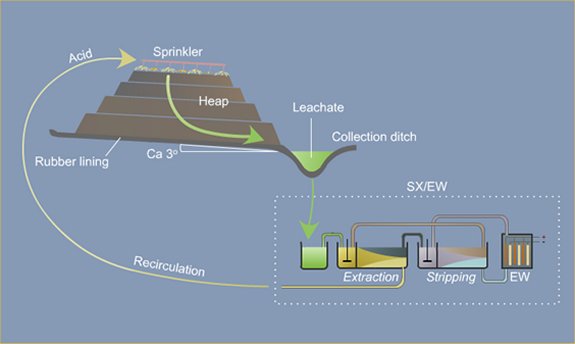
The largest U.S. precious metal heap leach is the Round Mountain, Nevada, operation with over 150,000 tonnes/day of ore going to crushed or run-of-mine heaps, at an average grade of 0.55 grams gold/tonne. This chapter follows the North American convention of “ton” for short ton and “tonne” for metric ton). Worldwide, Newmont’s Yanacocha, Peru, operation holds the record, with a 2002 target of nearly 370,000 tonnes/day, at an average total reserve grade of 0.87 grams gold per tonne. On the other end of the scale, some very high grade ores – up to 15 grams per tonne (0.5 oz/ton) – are being successfully processed at rates of several hundred tonnes/day (Sterling, Nevada; Hassai, Sudan; Ity, Ivory Coast). A cursory worldwide summary in late 2001 was able to identify 78 active precious metal heap leaches worldwide, of which 34 were in the U.S. (22 in Nevada). The survey no doubt missed many operations, so the worldwide total is certainly over 100. To provide a basis for this chapter, technical and/or cost data were gathered from 37 of these operations. Because many operations impose restrictions on the release of detailed data, composite results are presented.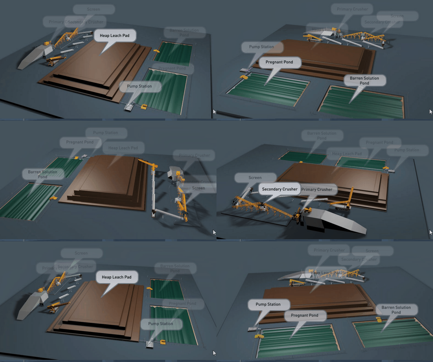
Nevada was the “birthplace” of modem gold heap leaching in the late 1960’s, and is only now giving up its dominance of this technology. Other very large gold districts – notably the pre-cambrian shield areas of Canada, Australia and South Africa – show relatively few heap leaches. There are several reasons for this geographic concentration, but the primary reason is that Nevada gold deposits tend to have been created by low-energy geologic processes – near surface hot…
Heap Leaching Copper Ores
The recovery of copper by leaching from relatively low grade ores containing both oxidized, and sulphide minerals is rapidly gaining in commercial importance. There is an economic limit, below which certain ores can not be treated by concentration methods, and material with values below this limit must be discarded, possibly to be treated later, or the copper must be extracted by wet processes.
Heap leaching has been carried out by the Phelps Dodge Corporation, Copper Queen Branch, for several years, and to-day its plant is a large producing unit. The Ohio Copper Co. at Bingham, Utah, has been leaching in place since 1919. Many other leaching operations are also being carried out in various parts of the United States and in foreign countries. The plant at Rio Tinto, Spain, may be considered the father of heap leaching.
In heap leaching the ore is usually heaped as it comes from the mine without any breaking on crushing treatment. Frequently, pieces of rock 5 or 6 feet across a face are found in the heaps. Solution is added to the ore at the surface and seeps downward by gravity and is collected in a solution sump.
Solution is usually added to one section of a heap and, after a certain quantity has been added the solution is added to another section. Sometimes weeks, or even months elapse between additions of solution to a given section.
Four factors are essential to the successful leaching-of any copper-bearing ore:
- A solution that will attack the copper minerals must get into the body of the ore particles
- the copper minerals must be dissolved by the solution,
- the solution containing the copper must find its way out of the voids into the main solution stream, and
- the copper in solution must be recovered by some means of precipitation.
The United States Bureau of Mines at its Southwest Experiment Station, in cooperation with the department of mining and metallurgy, University of Arizona, has undertaken a study of these fundamental factors involved in the leaching of copper ores. So far, the study has been limited to the first three factors, which are those involved in the leaching operation itself. In leaching a given ore the rate of extraction is not instantaneous but goes on slowly, and the factors of penetration, dissolution, and diffusion, go on simultaneously and not in successive stops. However, these steps can be studied only by segregating them so as to have only one factor entering at a time. The results thus obtained lend themselves to comparisons that can be used in commercial practice.
This paper presents a resume of the results obtained in the heap- leaching studies made at the Southwest Experiment Station, and the general conclusions which have been drawn.
Former papers have described in detail the experimental procedure and the results obtained in the study of:
- The ingress of solutions into ores during leaching,
- the dissolution of various cooper minerals, and
- the removal of soluble copper from leached ores.

Ingress of Solutions into Ores
In leaching an ore, the solution must first permeate the ore in order to come into contact with the copper-bearing minerals. There are, in general, two classes of voids in rocks:
- Fractures and cleavage planes and
- pores of capillary size or smaller.
The crevices and cleavage planes are usually of such a nature that they are open along one side or at both ends. For a solution to enter these openings it must mechanically push the gas out of the voids. As these openings are not in general in a horizontal position, there may be a larger hydrostatic head at one end of the opening than at the other. It is not particularly difficult for solutions to enter large voids. In the second class of voids, the pores may extend through the rock or they may be connected by a network to one another so that they are open at both ends, but pores open at one end only are also present. Even in small pores open at both ends, if solution penetrates simultaneously from both ends, the pores act as though closed at one end. In the case of a pore closed at one end, solution can penetrate only by replacing the gas within the pore. A solution will not penetrate unless the pressure within the pore is less or equal to the outside pressure. The gas in the closed part of the pore must either dissolve in the penetrating liquid or diffuse through it if penetration takes place.
The movement of liquids in rocks through super-capillary openings (circular, openings greater than 0.508 mm. in diameter, or sheet openings greater than 0.254 mm. between walls) is probably governed by the ordinary laws of hydrostatics. Poiseullle’s law probably governs the movement of liquids in capillary openings (circular openings 0.0002 to 0.508 mm. in diameter, or sheet openings 0.0001 to 0.254 mm. between walls). Flow through subcapillary openings would be infinitely slow, as the attraction of solid molecules. extends from wall to wall, and no liquid would be free to move, as it is attracted to the walls as a film.
A description has been given elsewhere of the apparatus and procedure used for determining:
- The rate and volume of penetration of solutions into ores,
- the total volume of voids within particles of ores, and
- the density of ores.
Table 1 shows the rate at which water penetrated into various sizes of a typical porphyry ore of the, Southwest. The data show that the time needed for a given percentage penetration increases markedly with increases in size of particles.

Surface Tension
The general opinion has been that solutions entered the pores of rocks by capillarity. If capillarity is the governing factor, then by changing the surface tension of the penetrating liquid, the rate of entry of solution should also be changed. Tests were made in which the surface tension of water was lowered from approximately 75 dynes to about 25 dynes per centimeter by adding enough sodium bleats to make a saturated solution, but the rate of entry of solution into the ore was practically identical with that of pure water.
Solubility of Gas in Voids
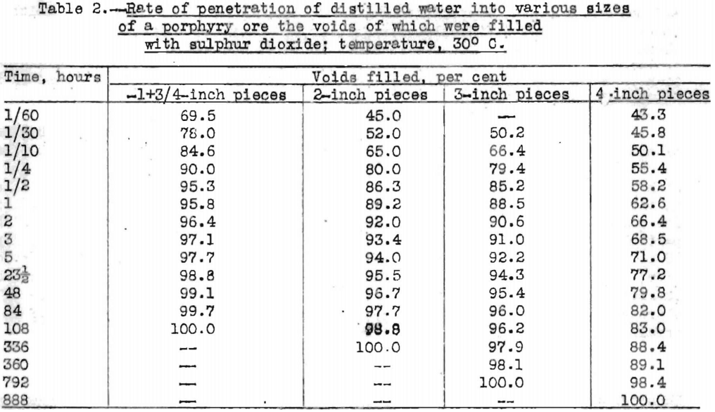
As surface tension has little or no effect upon the rate of penetration of solution into ores, the rate must be governed primarily by some other factor, which is indicated to be the solubility in the penetrating solution of the gas or gases within the voids of the ore. The solubility of sulphur dioxide in water is 3,957 cubic centimeters in 100 cubic centimeters of water at 20°C., whereas the solubility of air is 1.8 cubic centimeters in 100 cubic centimeters of water at the same temperature. Data in Table 2 show the rate at which distilled water penetrated into various sizes of a typical porphyry ore which had been evacuated and the voids filled with sulphur dioxide. The ore was the same as that used in the tests summarized in Table 1. When the voids were filled with sulphur dioxide, water penetrated more rapidly, especially during the early part of the impregnation. Not only was the rate of penetration faster, but the total volume of penetration was also greater.
Temperature
Measurements made at 2 to 3.5° C. and at 35° C. showed that the rate of penetration was more rapid at the lower temperature. For a given ore, 95 per cent of the total penetration that took place was attained in 40 hours at 2 to 3.5° C., whereas 50 hours was required at 35° C. As the solubility of gases in water increases with a decrease in temperature, the solution might be expected to penetrate at a faster rate at the lower temperature.
Various Solutions
There is surprisingly little difference in the rate of penetration of various kinds of solutions into rocks; 5 per cent copper sulphate, 2 per cent sulphuric acid, 2 per cent copper sulphate or ferrous sulphate plus sulphuric acid, 2 per cant ferric sulphate, and distilled water have very nearly the same rates of penetration.
Manner of Penetration
It has been found that in most ores the solution enters along fractures and cleavage planes and that from these larger fractures it gradually seeps into the rest of the rock. The first penetration takes place very rapidly along these crevices and fractures, and the small voids are filled more slowly from these points of initial penetration. Photographs demonstrating this phenomenon can be found elsewhere.
Dissolution of Various Copper Minerals
Leaching Oxidized Minerals
The oxidized minerals of copper—azurite, malachite, chrysocolla, and tenorite—are soluble in sulphuric acid and in ferric sulphate solutions. Approximately 100 per cent of the total copper is soluble in one hour at 35° C. in sulphuric acid or in acidified ferric sulphate solutions when the size of mineral is minus 100 plus 200 mesh. In 1 or 2 per cent neutral ferric sulphate the dissolution is slower, but in nearly every instance the mineral is completely dissolved in 24 hours or less. The rate of dissolution in 5 per cent ferric sulphate is about the same as in sulphuric acid or in acidified ferric sulphate.
Cuprite Leaching
When cuprite is leached with sulphuric acid in the presence of excess atmospheric oxygen, approximately 100 per cent of the copper in pieces up to 4-mesh in size is converted into the soluble sulphate in 20 days at 35° C. With a minus 3 plus 4 mesh product, approximately 94 per cent is rendered soluble in the same time. For pieces 100 mesh or smaller in size, 24 hours is sufficient for complete dissolution. When cuprite is treated with acidified ferric sulphate, particles up to 3 mesh in size are completely dissolved in 8 days and in 3 days 99 per cent is dissolved. For 100-mesh or smaller particles, one hour is sufficient for complete dissolution. When cuprite is leached with sulphuric acid in the absence of oxygen (as, for example, in closed bottles in an atmosphere of m nitrogen) only one-half of the copper is rendered soluble, and one-half of it remains as metallic copper, according to the reaction:
Cu2O + H2SO4 = CuSO4 + Cu + H2O
When cuprite is leached, either in the presence or in the absence of oxygen, a layer of metallic copper forms practically as soon as the mineral comes in contact with sulphuric acid. This metallic copper forms a difficulty permeable layer on the surface of the particles that slows down the dissolution. The metallic copper may be converted to copper sulphate by the aid of an oxidizer. Atmospheric oxygen is a fairly good oxidizer but ferric sulphate is a much better one. On particles 100 mesh or smaller in size this metallic coating of copper does not markedly hinder the rate of dissolution, but it is very harmful for larger sizes.
Leaching Chalcocite
Chalcocite is the principal sulphide mineral encountered in leaching. When it is leached with ferric sulphate, the dissolution takes place in two stages, which may be written:
Cu2S + Fe2(SO4)3 = CuSO4 + 2FeSO4 + CuS, and
CuS + Fe2(SO4)3 = CuSO4 + 2FeSO4 + S.
The first reaction is much more rapid than the second. For particles of mineral 10 mesh or smaller, approximately 50 per cent of the total copper is converted into the soluble sulphate in 24 hours at 35° C., whereas approximately 20 days is required to dissolve the other half. Particles as large as 2 or 3 mesh dissolve at only a slightly slower rate than minerals crushed as fine as minus 150 plus 200 mesh. An oxidizing agent is necessary to dissolve chalcocite. Sulphuric acid in the absence of oxygen or water even in the presence of oxygen have practically no dissolving effect upon the mineral. Sulphuric acid in the presence of excess atmospheric oxygen attacks the mineral, but does so more slowly than ferric sulphate solutions. At 35° C. the rate of dissolution is practically the same in ferric sulphate and in ferric chloride. The rate of dissolution increases with increases in temperature. In 48 hours 50, 59, and 87 per cent of the copper was dissolved from minus 100 plus 200 mesh chalcocite at 23, 35, and 50° C., respectively.
Bornite Leaching
Data on the rate of dissolution of various sizes of bornite, Cu5FeS4, in acidified ferric sulphate are given in Table 3.

The rate of dissolution of bornite is markedly increased by increases in temperature. When minus 100 plus 200 mesh bornite was leached with acidified ferric sulphate 64 per cent of the copper was dissolved in 1 day at 50° C., in 4 days at 35° C., and in 14 days at 23° C. Eighty per cent of the copper was dissolved in 6 hours at boiling temperature. Bornite dissolves more rapidly in ferric chloride than in ferric sulphate. Sulphuric acid plus air attack bornite more slowly than ferric sulphate solutions.
Covellite Leaching
Table 4 gives data on the rate of dissolution of various sizes of covellite in acidified ferric sulphate.
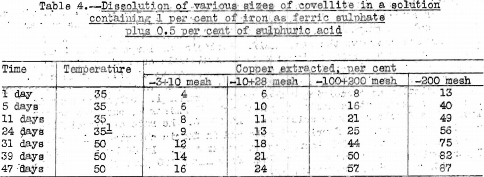
The rate of dissolution of covellite increased with increases in temperature. For a given sample, 81 per cent of the copper was extracted in 14 hours at 98° C., 81 per cent in 22 days at 50° C., and 41 per cent in 24 days at 35° C. The rate of dissolution was more rapid in ferric sulphate than in ferric chloride at 35° C., but the rates were virtually the same at 98° C. Covellite dissolved in sulphuric acid in the presence of excess atmospheric oxygen about half as rapidly as in ferric sulphate.
Chalcopyrite Leaching
Chalcopyrite is frequently found in leaching ores, but it is not appreciably attacked by common solvents at ordinary temperatures.
Chalcopyrite is a closely textured mineral, and its rate of dissolution is greatly increased by fine grinding. Data on the rate of dissolution of chalcopyrite are given in Table 5.
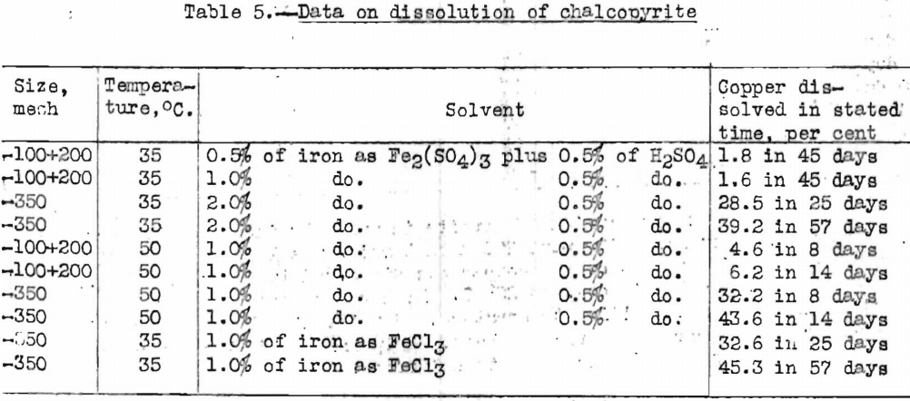

The foregoing data show that the rate of dissolution is faster when the mineral is more finely ground, that the rate increases with an increase in temperature, and that the rate of dissolution is more rapid in ferric chloride than in ferric sulphate.
In heap leaching an appreciable amount of the copper in chalcopyrite may be extracted owing to the long period of contact with solutions, and the possible rise in temperature of the ore during weathering.
When chalcocite is leached with ferric sulphate one-half of the copper dissolves rapidly leaving a residue approximating CuS which dissolves much slower; with bornite the copper is attacked preferentially to the iron; while with chalcopyrite the mineral dissolves as chalcopyrite; that is, at any stage in the dissolution (up to an extraction of approximately 45 per cent of the copper which has been the maximum studied), the ratio of Cu:Fe:S in the residue remains the same as in the original mineral. With covellite at any stage in the dissolution the residue has approximately the same ratio of Cu:S as the original mineral.
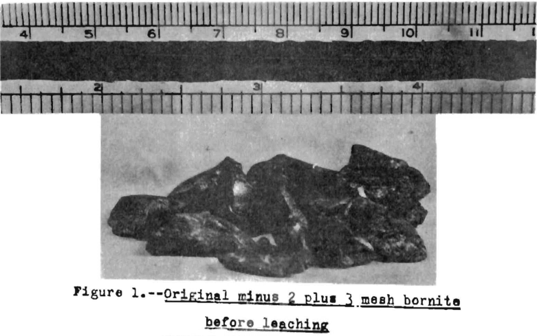
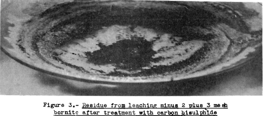
When large pieces of chalcocite, bornite, or covellite are leached with ferric sulphate the particles do not disintegrate and the residue become a powder. The particles, after leaching, nearly retain their original outline, and very little powder is formed. Apparently the sulphur left behind retains the original form of the mineral particles. When carbon bisulphide is added to the residue, the sulphur dissolves and the particles collapse. Figures 1, 2, and 3 demonstrate this phenomenon. Figure 1 shows minus 2 plus 3 mesh bornite before leaching; Figure 2, the residue after leaching for 14 days at 50° C. with acidified ferric sulphate; Figure 3, the residue after treatment with carbon bisulphide. In the 14-day period of leaching 91 per cent of the copper was dissolved.
Removal of Soluble Copper from Leached Ores
In heap leaching, because the solution is added to a given section of the heap and because after a certain quantity of solution has been added the leach solution is added to another section, several months may elapse between additions of solution to a given section. Heap leaching, therefore, results in a process of alternate wetting and drying. When the surface is dried, evaporation pulls solution to the surface where the dissolved salts crystallize as the solutions evaporate, and the next wetting operation removes part of these salts. At the same time that the salts ore removed by washing some solution penetrates into the cavities, cleavage planes, and pores within the ore. If all of the moisture within the ore was removed during the drying cycle, all of the copper salts would be precipitated, partly at the surface and partly within the ore. When the ore is washed, the distance that the solution penetrates into the ore is a function of the time of washing.
The alternate wetting and drying tests carried out in the laboratory could not easily be duplicated in heap leaching. In the laboratory the surfaces of the ore may be completely dried, and it is possible to dry the entire sample.
In heap leaching, a complete drying would be practically impossible. As a heap may contain several million tons of ore complete drying, even of the surface, could hardly be expected. Experiments have shown that the copper can be brought to the surface even though the particles of ore are only partly dried.
With a 0.5-hour period of drying and a 0.5-hour period of washing and the cycle repeated until nearly all of the copper was extracted, 80 per cent of the total copper in solution was extracted from 3-inch pieces of ore in 6 hours, whereas 44 hours was required for 5 to 6, inch pieces. This shows the advantage of employing small pieces of ore.
In heap leaching, very short periods of alternate wetting and drying can not be maintained, but laboratory work has shown the advantage gained by keeping the cycles as short as possible. With 3-inch pieces of ore, an extraction of 80, per cent of the water-soluble copper was obtained in 6 hours with a 0.5-hour period of drying and a 0.5-hour period of washing, whereas 25 hours was required for a 6.0-hour period of drying and a 2.0-hour period of washing. Any advocacy of shorter cycles in altennate wetting and drying presupposes that the heaps are porous and wall, aerated.
The soluble copper can be removed by alternate wetting and drying in approximately 15 to 25 per cent of the time required to remove it by flood, washing, provided the washing and drying periods are as close to each other as possible but long enough to permit a fairly thorough drying of the charge and soaking in of the leaching solution. As an example, it took approximately 150 hours to remove 90 per cent of the water-soluble copper by vat washing from the minus 1 plus ¾ inch size of a porphyry ore saturated with copper sulphate, where as only 31½-hours was required by alternate wetting and drying when the period of drying was 4.0 hours and the period of washing 0.5 hour.
A rapid movement of air past the surface of the ore promotes rapid drying. Anything that interferes with the circulation of air slows down the rate of extraction, thus demonstrating the necessity of having an open heap where free circulation of air is possible. Slime or other material that will coat the surface would also hinder drying. The fate of extraction is also increased by an increase in temperature.
When a rock is saturated with copper sulphate and then dried, the crystallized salt is disseminated throughout the entire rock, especially along the fractures and cleavage planes. A large part of the copper is brought to the surface in the first drying operation. Some of the copper is crystallized in the interior of the rock, especially along larger fractures und cleavage planes. Photographs demonstrating this phenomenon can be found elsewhere.
Conclusions
In leaching, the three factors (1) ingress of solutions, (2) dissolution of minerals, and (3) removal of the soluble copper are interdependent and work simultaneously. The speed of leaching can be no faster than tho slowest step. Enough solution can not enter a rock at one time to dissolve the copper minerals completely unless the copper content of the ore is very low. A sample of ore weighing 2,000 grams may soak up about 40 cubic centimeters of solution. If the ore contains 1 per cent of copper, and the solution coming out of the pores contains 20 grams of copper per liter (assumed), 1,000 cubic centimeters of solution or approximately 25 renewals of the solution within the voids would be necessary. Frequent removals of solution and much time is required to get sufficient solvent into contact with the minerals and to wash out the dissolved copper.
In heap leaching with oxidized ores the slowest step is probably the removal of the soluble salts. If the copper exists as sulphide (chalcopyrite excepted), about 20 days will be required for complete dissolution of the copper, granting contact of mineral and solvent solution during the entire period. In this instance, the slowest step is probably the chemical one or the dissolution of the copper sulphide, granting that conditions found in the laboratory hold in practice.
The rate of dissolution of the copper minerals is a chemical factor; and in heap leaching practice, for a given solvent, the rate can not be markedly changed. Although the rate of dissolution increases with increases in temperature, it is difficult to control temperature in a large heap. Actual temperature measurements within the heaps usually indicate a higher temperature than that of the outside air, which shows that the heat from chemical reactions is fairly well stored within the heap. It may therefore be possible to increase gradually the temperature within the heaps by adding warm solution. In the Southwest the solutions could be warmed by the sun in summer.
Waste smelter gases, if available, might be used with a heap leaching plant. If waste gases are allowed to enter heaps and displace the air present before water is added to a given section of the heap, the solutions should penetrate more rapidly into the interior of the rocks. Also, waste gases would add a reagent that would help to dissolve the copper minerals present.
From a practical standpoint, the method of speeding up the rate of extraction is to crush the ores finer. Crushing the ore particles would not only decrease the time required for saturation but it would also make the ore more amenable to leaching by open cleavage planes and crevices in the ore particles and by shortening the path required for the leaching solutions to come into contact with, the mineral particles and for the dissolved copper to be brought to the surface. Crushing to a smaller size than 2 or 3 inches might produce too many fines, which would tend to counteract the advantages of crushing.
Another means of speeding up the extraction is by recirculating solutions over the heap, frequently mine water containing neither acid nor iron salts is passed over the ore, but owing to the weathering of pyrite and other sulphides there is a considerable concentration of sulphuric acid and salts of bivalent and trivalent iron in the effluent solutions. As chalcocite is amenable to leaching by solutions of salts of trivalent iron, there is good reason for recirculating at least a part of the effluent solutions. To avoid “plugging” the leaching column with flocculent hydrated iron precipitates, the solutions recirculated should contain some free acid.
Heaps should be laid down on prepared footings to prevent the loss of solutions by seepage. This is especially true if pregnant liquors containing copper are recirculated.
HEAP LEACHING COURSE
Heap Leach Pad Design
Because flow is downward in percolation leaching, the leach pad is the most important element of the solution containment system. The leach pad supports the ore heaps, collects solution flowing through the heaps, transports the solution laterally to drainage pipes or ditches, and prevents toxic or hazardous chemicals from penetrating into the ground. The leach pad site and its topography should be selected to be free from flooding or other natural hazards. The foundation must be stable to prevent movement or cracking of the pad liner under the weight of the ore heaps, which may eventually reach heights of nearly 60 m at some multilift cyanide heap leaching operations.
The minimum leach pad system consists of:
(1) a prepared foundation and bedding layer, (2) an impervious liner, and (3) a covering layer of coarse rock (drain blanket) to facilitate drainage of percolating solutions and prevent rupture or tearing of the liner.
Usually the drain blanket will contain a network of plastic pipes, constituting a French drain, to facilitate removal of the leachate. The general features of a heap leach pad are illustrated in Fig. 4.1. The heap leach pad is protected from extraneous water by diversion ditches or berms and on the down slope end it has a solution collection ditch, which also has an impervious liner. The slope and permeability of the drain blanket, which must be adequate to carry away percolating solution, are important factors in determining the actual rate at which leaching solutions penetrate the liner. However, if the slope is too great the heap may be unstable and slump or slide laterally. Proper foundation preparation is necessary to prevent movement and tearing of the liner. The drain blanket will also prevent polymer liner damage by sunlight, prevent evaporation and cracking of clay-soil liners, and protect the liner during heap construction.
Factors to be considered in liner selection and in leach pad and settling pond design are: seepage rate, settlement of the foundation, slope stability for heaps on slopes, weathering, solar radiation, and regulatory requirements.
Two types of impervious liners are in use:
(1) clay and clay-amended soil liners and (2) polymeric sheet materials, sometimes referred to as “geomembranes”.
Combinations of both types are in use and often multiple liners are required. Examples of typical geomembrane impervious liners sections arc illustrated in Fig. 4.2. Asphalt road paving material has also been used in impervious liner systems, especially with reusable leaching pads.

Clay liners and soil liners, with or without clay additives, consist of selected materials placed in thin layers and compacted to prescribed moisture content and density specifications. The soil borrowed to produce the liner must be tested and the optimum additions of water and imported clay need to be determined in advance. The materials must be thoroughly mixed prior to introducing water, followed by further mixing and compaction. Permeabilities of liners are often specified by regulation with the maximum allowable hydraulic conductivity in the range of l()-5-10-6mm/s (1-0.1 ft/yr). Generally, the higher the amount of clay and plasticity of the clay- soil mixture, the lower will be its ultimate permeability for a constant liner thickness (see Fig. 4.3). However, highly plastic soils are difficult to mix because they tend to form clumps. Usually 5% bentonite, cither naturally present or added to the soil, is sufficient to obtain the required low hydraulic conductivity.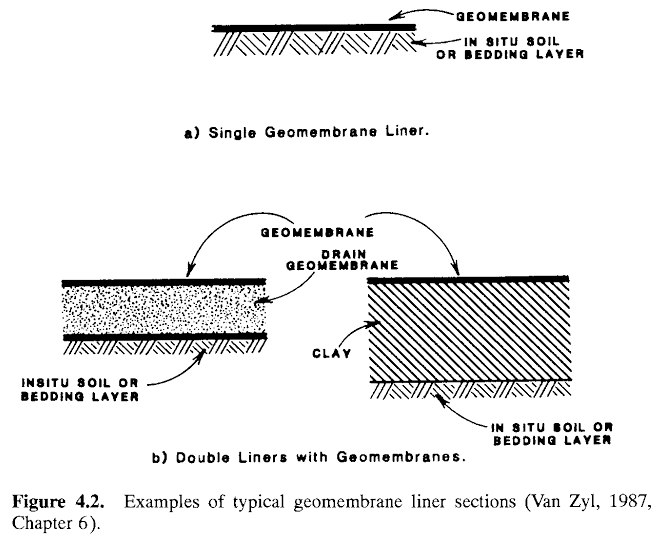
Soils are tested by a standard Proctor Compaction Test. The relationships between optimum water content, dry density, and the resulting hydraulic conductivity are illustrated in Fig. 4.4. After compaction, ideally, all of the clay/soil void space will be filled with water but without any excess water.
Algorithm for Grading Optimization
To optimize the leach pad grading the pad area is discretized into a grid of points, each point representing the elevation of the natural ground surrounding the point (this grid arrangement has direct practical application for building pads, see Welsh. The variables for solution are the cut and fill at every grid point. The objective function is the sum of the cumulative cost of fill or cut (fig. 2) for every grid point; this needs to be minimized. This function is usually non-linear, meaning that one must be cautious in accepting the obtained optima as global optima. If the objective function is not too “wavy” (usually the case in the real world), and the domain is kept tight, e.g. by limiting the cut and fill values to reasonable depths, the solution is likely to be a global optimum. The constraints are the design criteria required for the functioning of the pad. Luckily, in the leach pad problem, many of the most important design constraints can be expressed as linear functions. Any number of design constraints are possible.
Some typical constraints are:
a. maximum /[minimum] longitudinal slope of pad
b. maximum longitudinal slope of pad in the toe area (the toe length is defined by the user)
c. maximum cross slope of cell
d. maximum /[minimum] slope of solution collection channel
e. maximum depth of cut /[fill]
f. maximum volume of imported fill available
The algorithm works on the grid, or matrix, of elevations of natural ground levels within the pad area. These can be obtained from a topographical map either by hand, or preferably, by an automated CAD procedure. The matrix columns are set up to run in the direction of the pad cells, with the first row of each column being the cell lowpoint. The pad can be any arbitrary shape so long as each of the matrix columns is continuous, see fig. 3. (This makes sense physically as for continuity of solution flow one would not want to have disjoint cells). The lengths of each column differs according to the pad shape. The low point (or first row) of each column can be thought of as a point along the length of the solution collection channel; each of these points may be in a different row in each column. The model also requires an initial definition of the desired low point of the graded pad. Obviously, this must be a point somewhere along the low edge of the pad.
The crux of the method is to find a simple way of describing the constraints and objective function so that the power of mathematical programming can be used to find an optimal grading.
Method:
- Set up a matrix of points defining the pad shape and natural ground topography within the pad. The spacing of matrix points and the grid orientation (which sets the cell, or flow, direction) are set by the user. Define the desired low point of the graded pad.
- Create a continuous and smooth function that approximates the cumulative cost of fill/cut with depth, (see fig 2). This function may be derived from the rates, as fig. 2 was derived from fig. 1, or it may be directly defined eliminating any approximation. This function may be non-linear.
- Create an objective function, which is just the sum of the cumulative cost of cut or fill for every grid point within the proposed pad area.
- Specify all constraints mathematically, each constraint must be applied to a specified set of grid elevations. For the constraints listed above (a to f) the procedures for defining the constraints over the specific sets of grid elevations are as follows:
a. For every grid elevation in every column, constrain the upstream grid elevation (if it exists) to at most /[least] the grid spacing times the maximum /[minimum] slope higher than the grid elevation under consideration.
b. For every grid elevation in every column in the region of the toe of the heap, constrain the upstream grid elevation (if it exists) to at most the grid spacing times the maximum toe-slope higher than the grid elevation under consideration.
c. For every grid elevation in every row, constrain the grid elevations to the left and right to at most the grid spacing times the maximum cross slope lower or higher than the grid elevation under consideration.
d. For every grid elevation along the channel (i.e. the first grid elevation in a column), constrain the grid elevation upstream (if it exists) to at most /[least] the grid spacing times the maximum /[minimum] channel slope higher than the grid elevation under consideration. Do this for all channel grid elevations on both sides of the low point.
e. For every grid elevation constrain the cut /[fill] (cut is defined as negative) to greater /[less] than the minimum /[maximum] specified cut /[fill].
f. Constrain the sum of the volumes of cuts plus fills over all grid elevations to less than the maximum available imported volume of fill. - Use standard mathematical programming algorithms, e.g. simplex, or Karmaker to solve for unknowns, i.e. the cut or fill at every grid point, minimizing the objective function, or grading cost.
- Check solution, especially if objective function is highly non-linear.
