Often we hear that copper concentrates have contaminants which affect the incomes to be obtained by commercialization. Well, one of the worst contaminant is bismuth because is difficult to remove during smelting process and the metallic copper to be obtained at the end of the process will be brittle and consequently its mechanical properties will be very bad. Ergo, the objective is focused to minimize the bismuth content in the copper concentrate which is usually chalcopyrite.
The bulk copper concentrate has no only chalcopyrite, also lead as galena and bismuth minerals such as cosalite, bismuthinite, aikinite, and wittichenite. The idea is separate lead and bismuth minerals from chalcopyrite by flotation. Thus, the copper concentrate will not have penalties for bismuth. Ideally, the bismuth content must be less than 1000 ppm.
Considering the fact that lead and bismuth are very close in the periodic table (number atomic: 82 Pb, 83 Bi), they can have similar behaviour during flotation. It means that collection and depression is very similar for both. So, applying the lead-copper separation technique is possible separate bismuth and copper too.
There are several methods for lead-copper separation. But, perhaps, the more common is employing NaCN as depressant for chalcopyrite, and also use a collector for improving bismuth flotation. The collector can be sodium isopropyl xanthate (SIPX). Previously to add sodium cyanide can be added activated carbon which absorbs reagents from mineral surfaces and residual reagents from the slurry.
The flotation gas to be used in roughing and cleaning flotation can be air or nitrogen, but preferently the latter because sodium cyanide is susceptible to be oxidized. If oxygen is present, the formation of cyanates and thiocyanates is favored; also the collector could have any grade of overoxidation. Air can be used, but the NaCN consumption will be higher, maybe twice than the amount added with nitrogen. The NaCN dosage during roughing flotation is about 70 to 80% of the total dosage. Thus, is good choice employ nitrogen as flotation gas.
Use a frother like MIBC is optional because its addition will depend of froth characteristics (i.e. texture, viscosity, bubble size).
Cleaning stages can be done employing mechanical or column cells. The latter one is very useful because washed water can eliminate fine particles of gangue present on the bubbles. During the cleaning stage is very important the NaCN dosage since some chalcopyrite particles can still present in the froth.
A key aspect in the separation is the redox potential. This value has direct relation with the NaCN dosage.
MINERALOGICAL PROPERTIES:
Here are presented some mineralogical properties of galena and some bismuth minerals.
| Property | Galena | Cosalite | Aikinite | Bismuthinite |
| Formula | PbS | Pb2Bi2S5 | PbCuBiS3 | Bi2S3 |
| Hardness | 2.5 | 2.5-3.0 | 2.0-2.5 | 2.0 |
| Specific gravity | 7.6 | 6.4-6.8 | 6.1-6.8 | 6.8-7.2 |
| Streak | Lead, gray | black | Grayish black | gray |
| Color | Lead, gray | gray | lead, reddish | Steel gray |
| Luster | Metallic/opaque | metallic | metallic | metallic |
| Molecular weight | 239.27 | 992.69 | 575.92 | 514.16 |
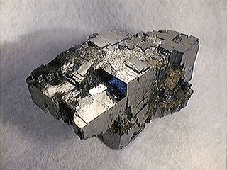
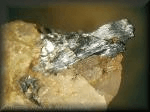
Galena Cosalite
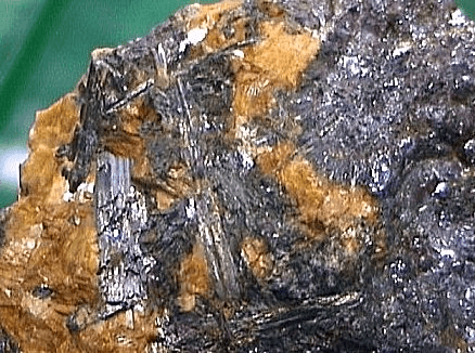
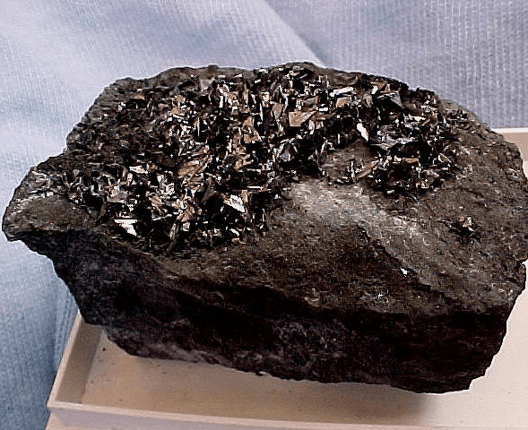
Bismuthinite Aikinite
Lead-bismuth sulphosalts have variable composition and most often occur as well developed, elongated crystal, mainly in central parts of galena sulphosalt concentrations. Creamy in reflected light, sometimes with noticeable blue tint, they reveal different anisotropy in blue, grey and brown colors. They can bear certain amounts of copper, silver and iron.
Galena coexisting with the sulphosalts shows variable bismuth and copper content. Thus, aikinite can form grains finer and frequently intergrown with galena. Figure 5 shows a typical phase diagram outlining the bismuth minerals and its relation with galena and copper.
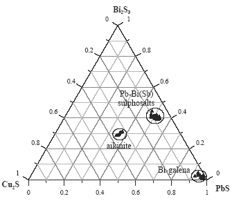
Composition of bismuth minerals
Some times, lead and bismuth minerals are intimately associated with copper minerals and liberation is very difficult. In this case, bismuth-copper separation is problematic and some of bismuth will be reported in the copper concentrate.
The minor element content of sulphide minerals changes regularly according to the type of ore deposits and also has a close connection with the formation conditions of the deposits. In the case of xenothermal type deposits, bismuth is concentrated in main constituent minerals that have the mineralogical structure of high temperature type.
Distribution of some contaminants such as arsenic, antimony, and bismuth is very low in the vein type deposits. However, bismuth is seldom present in the deposits of a copper-chloride vein type or in a copper-lead-zinc vein type. Porphyry type deposits can have present bismuth.
When bismuth is present as a solid solution in the sulphide minerals, it is concentrated in the final products such as copper, lead, and zinc concentrates.
FLOTATION:
The froth color in the flotation circuit is a reasonable parameter to qualify the state and performance of the circuit. Chalcopyrite has green color while galena and bismuth minerals present a bluish color, many times silvery when the performance is excellent.
A bluish froth with silvery iridescences indicates a good reagents dosage and consequently there are an excellent collection of lead and bismuth minerals. See Figure 6. In the first rougher cells, bubbles must be heavy, vigorous and viscous. These characteristics suggest a good recovery in these cells. See Figure 7.


Figure 6 Figure 7
In the last rougher cells, the bubbles must be slight and loose, but the blue color trends to be opaque. See figure 8.
Sometimes a small addition of frother can help to obtain the frothing characteristics mentioned above. Logically, the right addition of nitrogen influences the frothing. The bubble size in the first cells can be small than the last rougher cells. (Approximately, 1” and 3” in each case). See Figure 9.


Figure 8 Figure 9
Obtain black froth and dirty bubbles are an indication of excessive addition of activated carbon. Also, the bubbles will show the same texture in each cell. Most of the bubble size will be small (Approx. 1/4” to 3/8”). Few bubbles can have bigger size (Approx. 2” to 2.5”).
An excessive addition of activated carbon is harmful for lead and bismuth minerals flotation because all the reagents will be absorbed by the activated carbon. This problem will persist until saturate all the carbon and then, the froth can show other appearance. The dosage can be in the range 1 to 1.5 kg/tbulk.
An aspect very important is the NaCN dosage. Even, having a slight excess of activated carbon, the right addition depresses chalcopyrite. However, an excessive addition will make black froths and very heavy. The overdosage can be necessary when the zinc content in the bulk copper concentrate is more than 10%. Thus, for the conditioning tank the addition can be 45 to 50 % of the total dosage. The idea is has a residual cyanide for the next cells and consequently make small additions en last cells. This dosage can be 4 to 5 kg/tbulk. See Figures 10 and 11.

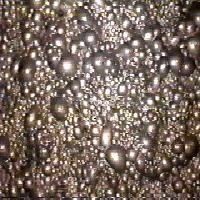
Figure 10 Figure 11
An inappropriate dosage of NaCN does not depress chalcopyrite and the bubbles will have a brilliant green color. If this happen, the sodium cyanide must be added immediately in the problematic cell or in the cell whose tailing is feeding the problematic cell. See Figures 12 and 13.
If suddenly appears the green color in the last cells, it means that lead content is decreasing in the feed (bulk copper concentrate) to the rougher circuit. In this case, the NaCN dosage must be increased and the collector dosage decreased slightly.
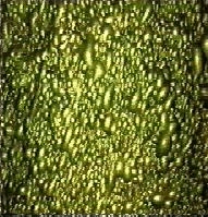
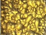
Figure 12 Figure 13
Collector addition in the first two cells must be 40 to 45% of the total addition to the rougher bank. An initial dosage is in the range 1000 to 1500 g/tbulk.
The pH at the rougher circuit must be less than 12, being a good value 11.8 with oxidation-reduction-potential (ORP) in the range -330 to -350 mV (calomel electrode). As the sodium cyanide is consumed by chalcopyrite, the ORP trends to reduce its value in the last cells. Thus, a typical value can be -250 to -280 mV. Work in the first cells with ORP values lower than -300 mV is totally inappropriate because chalcopyrite will float in excessive amount.
It is interesting mention that the froth depth must be higher in the first cells and reduce its value in the last cells but no excessively because the slurry can overflow from the cells and the bubbles formation could be problematic. See Figures 14 and 15.
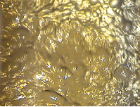
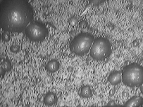
Figure 14 Figure 15
The solid percentage in roughing flotation must be in the range 38 to 40%. Work with diluted slurries can affect the hydrodynamic conditions of the cell and the efficiency of each reagent, mainly activated carbon and sodium cyanide.
With respect to cleaning stage, the columns must work with higher level in the first cleaning and increase the level in the second and third stage. The air flow must be high in the first cleaning stage and lower in the second and third cleaning stage. The addition of washed water to be employed is dependent to the gangue and fine particles present in the froth.
Some times, employ CO2 is beneficial because the froth depth can take lower values and consequently is possible increase until certain value lead and bismuth recoveries. But exist a disadvantage, chalcopyrite recovery will reduce its value.
If the separation circuit has on stream analysis system, the calibration must be checked frequently because mineralogy can change and consequently modify the curves employed during the calibration. An alternative method employs a panning dish to observe the final concentrate and rougher tails. The latter is the most interesting product because the bismuth content must be low. For instance, if we take a sample of rougher tails, approx. one liter. At the end of the washing, we could observe a dark blue sector of 0.5 cm2, this area represents approximately 400 to 500 ppm Bi.
FLOWSHEET:
The bulk copper concentrate from the copper flotation circuit is sent to the bulk concentrate thickener. The bulk concentrate is pumped to the storage tank.
The rougher flotation circuit is fed with the slurry from the storage tank, and treats the slurry through one row of conventional flotation cells. A rougher concentrate is obtained which is sent to the cleaning circuit. The tailings from the rougher flotation circuit are sent to thickening.
The rougher concentrate is cleaned in three stages employing column cells. The last column flotation stage produces the final Pb-Bi concentrate. Tailings from the first cleaning stage are processed in the rougher flotation circuit. Tailings from the second cleaning stage are processed in the first cleaning stage. Tailings from the third cleaning stage are processed in the second cleaning stage. The concentrates from each cleaning stage are fed to the next stage until obtain the final concentrate in the third cleaning stage.
The final concentrate is sent to the Pb-Bi thickener. The concentrate slurry is thickened and, when the thickener underflow density is high (60-65% solids) can be sent to filtration. The filter eliminates water from the thickened slurry and produces a cake that is sent to the storage bin which resends the concentrate to the packing section.
For more details see Figure 16
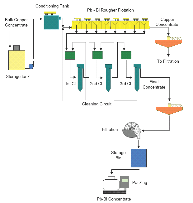
Figure 16. Flowsheet
REFERENCES:
• Cook, N. Bismuth Sulphosalts from Hydrothermal Vein Deposits of Neogene Age, N.W. Romania. Mitt. Osterr. Miner. Ges, 143, pp. 19-38. 1998.
• Golewbioska, B., and Pieczka, A. A Polymetallic Assemblage with Pb-Bi(Sb) and Cu-Pb-Bi Sulphosalts from Redziny in the Eastern Metamorphic Cover of the Karkonosze Granite. Mineralogical Society of Poland – Special papers, Zeszyt 20, 2002; Vol. 20, pp. 94-96. 2002.
• Wakamatsu, T. and Nakahiro, Y. Flotation Behaviour of Some Minerals bearing As, Sb, and Bi in Mineral Processing. Metallurgical review of MMIJ, Symposium Proceedings. Vol. 3, No 2, pp. 76-89. November1986.
• Binqing, Y. and An, Y. A Study of New Comprehensive recovery Technology of Bismuth and Molybdenum from tungsten tailings. GME’99. Proc. Global Metals Environmental Conference, pp. 484-488. May, 1999.
• Meech, J.A., Paterson, J.G. Improvements in Copper/Lead Separation with Activated Carbon. Society of Mining Engineers. Transactions, Vol. 264, 1758-1767, 1978.
• McQuiston, F.W. Pb-Zn-Cu: How Flotation’s Most Difficult Separation Is Being Done. Mining World. 49-52. February, 1958.
• Cabri, L., Petruk, W., Gilles, J. and Robitaille, J. Quantitative Mineralogical Balances for Major and trace Elements in Samples from Agnico-Eagle Mines Limited, Quebec, Canada. Analytical Technology in the Mineral Industries. Edited By Cabri, L., Bucknam, C., Milosavljevic, E., Chryssoulius, and Miller, R. The Minerals, Metals & Society, pp. 177-192. 1999.
• Gurkan, V., Arslam, F., Tufekci, S., and Tahsin, K. Beneficiation of Murgul Copper Ores. Innovations in Mineral and Coal Processing, Atak, Onai & Celik (Eds), pp. 661-666. Balkema, Rotterdam, 1998.
• Bogdanov, O.S. Yeropkin, Yu. I. & Leonov, N. B., The Use of Antioxidants and Nitrogen in Complex Sulphide Ore Separation, XVIII Int. Min. Proc. Congress, Dresden, Vol. II, 83-92, 1991.
