Table of Contents
In conventional gold and silver heap leaching systems, crushed or uncrushed ores are generally placed in a large rectangular pile on a pad surface and sprinkled with weak cyanide leach solutions. The solutions leach the ore particles in their downward migration through, the heap. Effluent solutions are usually stored, sent to a metal recovery system and thence, with added reagents, recycled to the heap. In some cases, a permanent pad is used and in others, a reusable pad is used where from the tailings are removed after leaching and a new heap is formed on the pad.
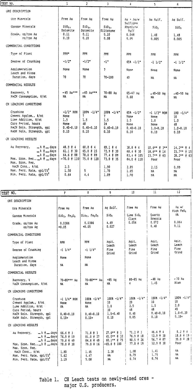
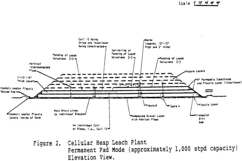
CH Leaching Plant Design
A CH Leaching plant is expected to consist of the following characteristic design components:
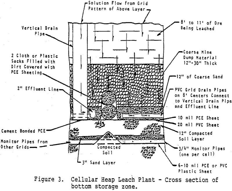
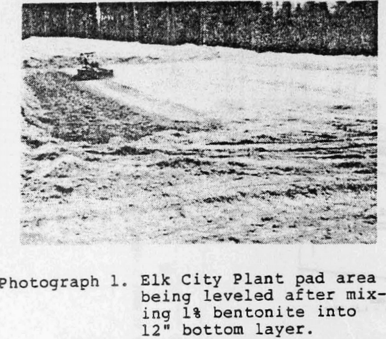
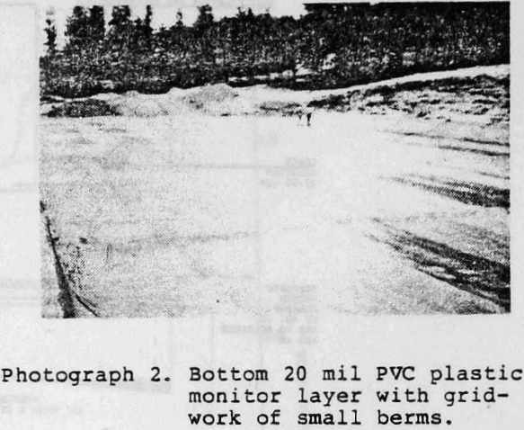
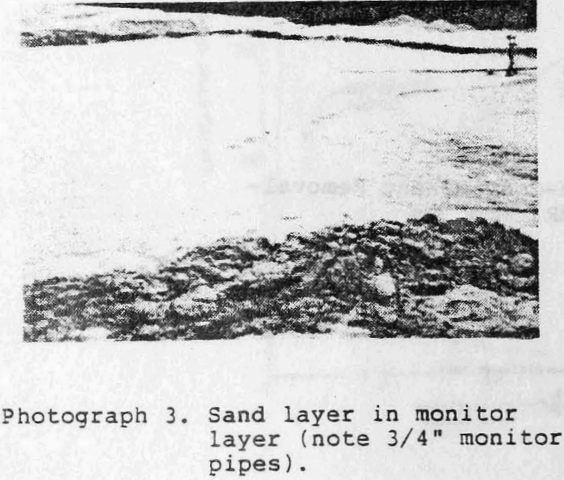
- A series of plastic, clay and sand layers that act as a monitor layer to detect the existence, size and location of leaks and act as a base layer to the heap.
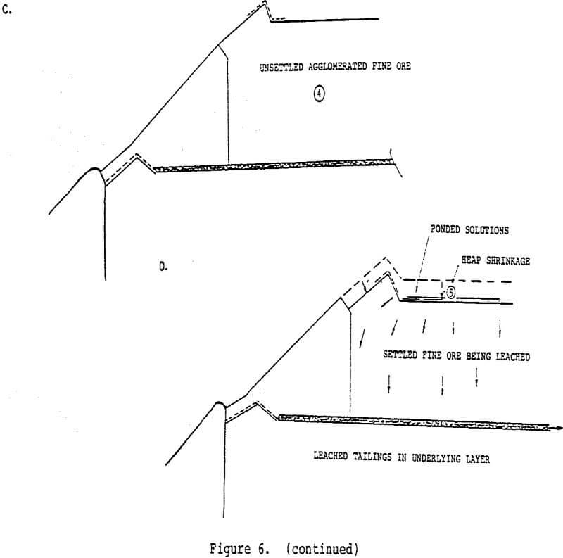
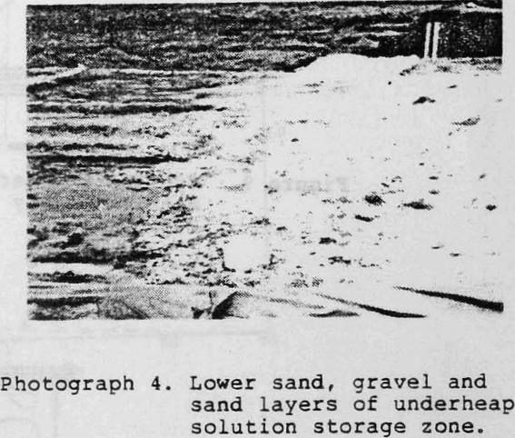
- A bermed gridwork of cells on top of the monitor layer, filled with thin top and bottom layers of sand and a thick intermediate layer of screened rock. Each of these cells acts as an individual solution collection and storage zone for the overlying leach cells.
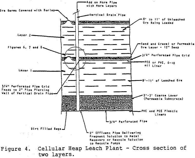
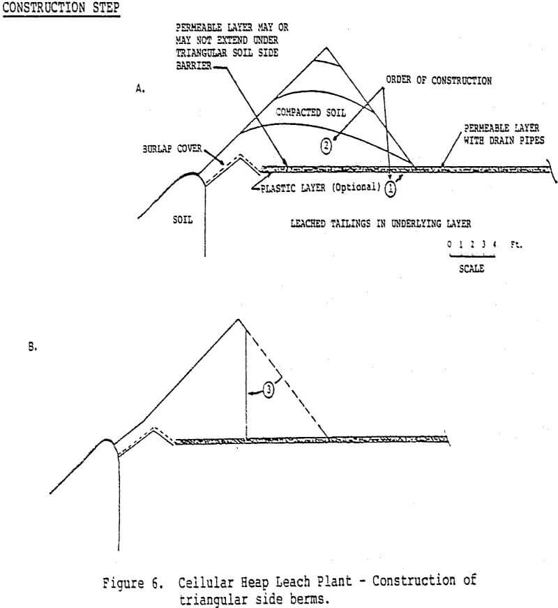
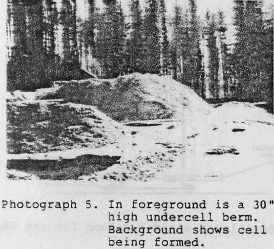
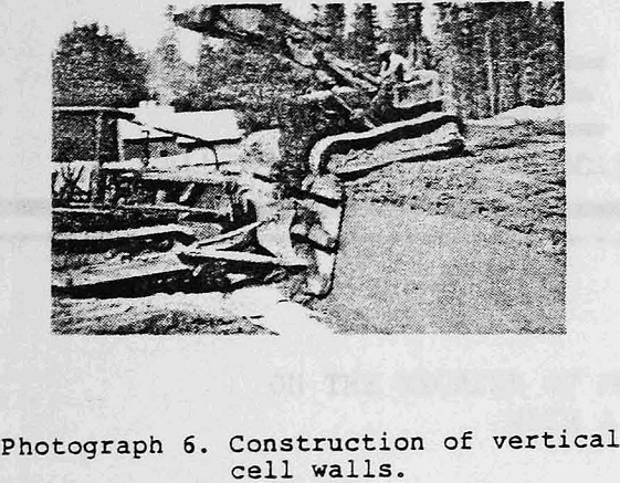
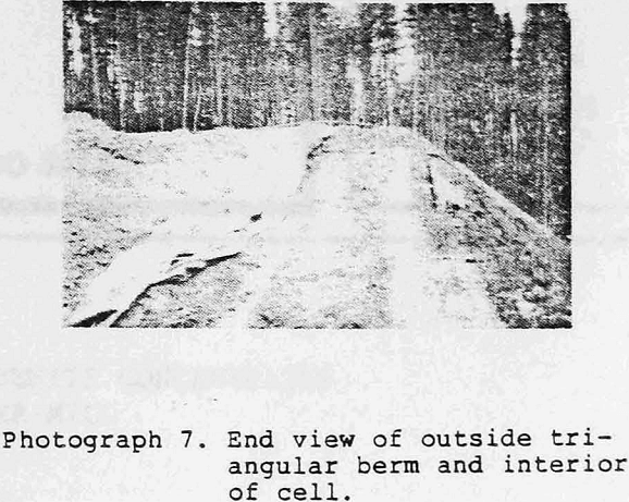
- Triangular earth berms on the exposed sides of each layer of the heap which act to contain the wetted ore within each of the individual cells, eliminate the need for leaching the heap sides by sprinkling and provide a heap side cover.
- Several heap layers, 1.8 m to 3 m (6′ to 10′) deep, with numerous over-lapping, individually formed and isolated, rectangular cells that contain the ore that is being, or that has been, leached. Each layer, and the cells therein, are successively formed and leached co-current with the mining operation. Thus, cells in the top layer of the heap are continuously being formed, leached in several stages, rinsed and sealed from further solution entry, and then covered over by a new cell in the advancing top layer.
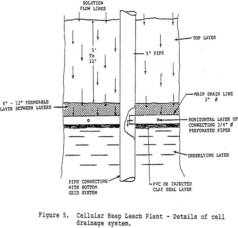
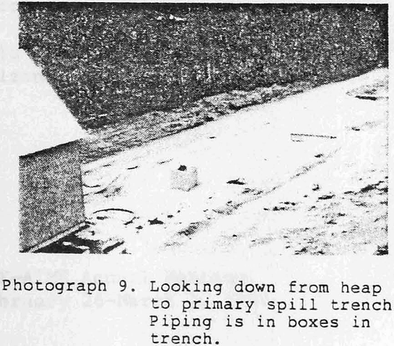
- The appropriate undercell permeable drainage zones and piping systems to drain effluent solutions from a cell being leached to an independent, underheap, cell storage zone; from this storage zone to a metal recovery system or to recirculation; and to effect the flow of influent solutions to the heap.
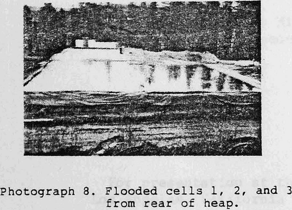
- Appropriate environmental safe-guards, i.e., spill trenches and drainage ditches.
- Access ramps to the top layer of the heap.
The heap is designed to have a top area that will give sufficient leach time to the desired plant capacity. For example, if a plant capacity of 1000 stpd is desired with a leach and rinse time of 60 days (determined to be the maximum economic recovery by lab testing), and each cell represents two days leaching time, the plant will need a minimum of 30 active cells plus about 4 inactive cells.
The preparation (agglomeration, screening and layering, addition of lime, etc.) of the ore prior to its addition to the cell is usually done in such a manner as to effect a leach percolation rate within a desired range (generally between 0.1 and 1.0 gph/ft²).
Laboratory Testwork
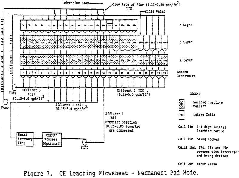
With but a few exceptions, CH Leaching lab tests on newly-mined ores showed better (3 to 17%) CH Leach metal recoveries than are currently being obtained on the same ores by large, conventional heap leach plants. Also, in some of the test cases, equal or slightly lower, but probably much more economical, CH Leach metal recoveries were obtained on ores that are currently being processed in large, high capital and operating cost, agitation leach plants.
A CH Leach plant was built at a cost of about $100,000 in the summer of 1983 near Elk City, Idaho and operated for about two months before being shut down for the winter. This plant is designed to treat about 100 short tons-per-day of old, finely-ground, stamp mill tailings that contain an average of about 0.129 oz of gold and 0.9 oz of silver per short ton. About one-half of the old tailings pile (a total of about 25,000 short tons) that exists at this property consists of coarse tailings that do not require cement agglomeration and are expected to yield maximum economic CH Leach gold recoveries of about 75% in 75 days of leaching. The finer, outside, portions of the tailings pile, which require cement agglomeration, leach much faster (30 days) and to a greater degree (90% recovery of the gold).
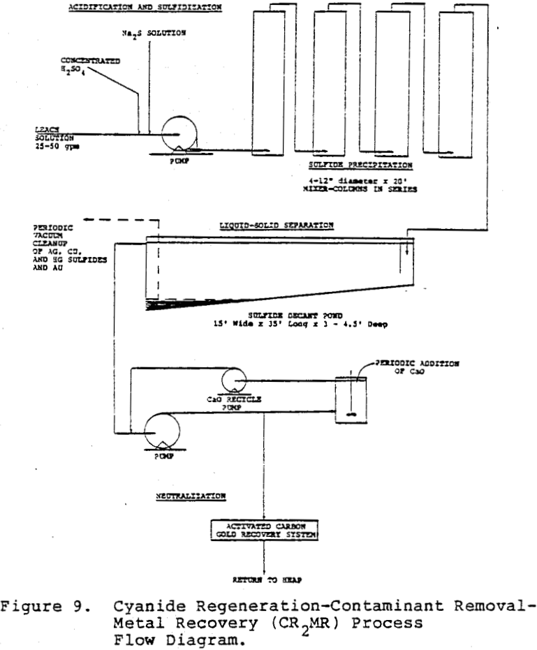
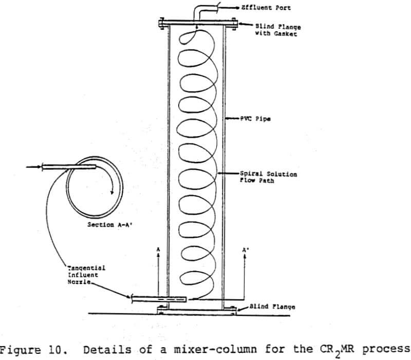
The Cyanide Regeneration Contaminant Removal and Metal Recovery Process
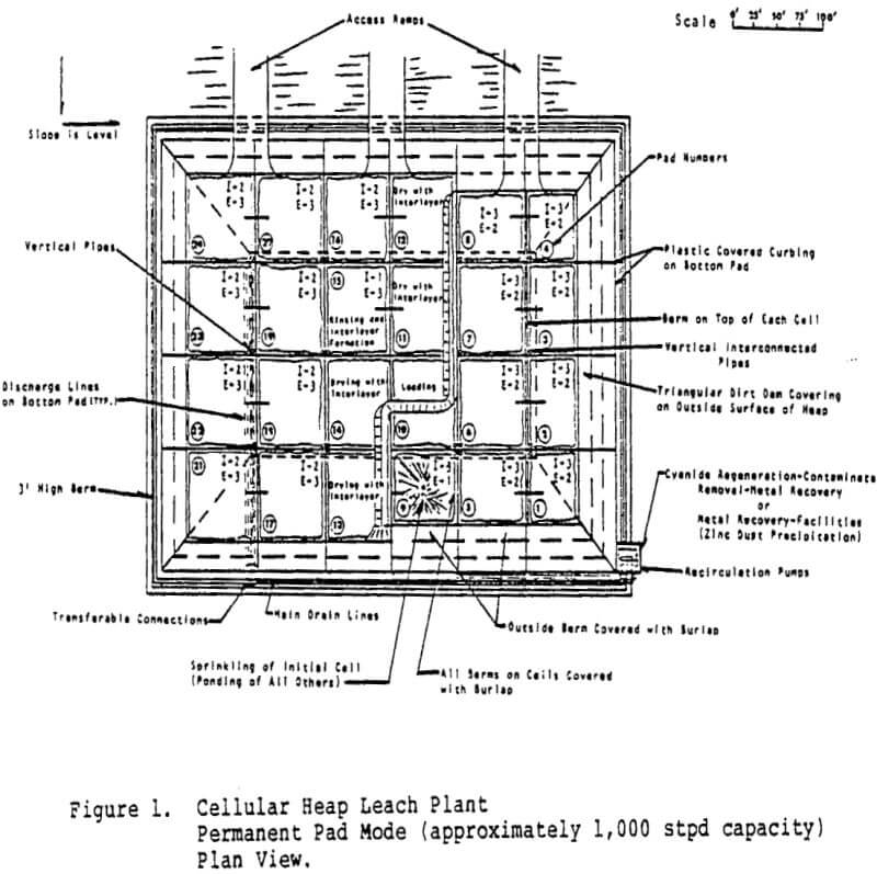
The principle processes that are in use today for recovering gold and silver from cyanide leach liquors are the Merrill-Crowe and the carbon adsorption processes. The Merrill-Crowe process is usually used on relatively high metal content gold and silver solutions containing a high proportion of silver. This process displaces a large amount of zinc into the leach solution as a complex zinc cyanate ion that may eventually foul the leach solution or end up as interstitial solution in the tailings.
Generally, the procedure used in these tests was to place 300 ml of leach solution in a separatory flask with a rubber-stopper and then add, by syringe injection through the rubber-stopper, the desired amounts of concentrated H2SO4. and Na2S solution. After shaking the sample for 10 minutes, the precipitate was settled and separated. A sample of the supernatant solution was analyzed for its metal content, and sometimes, after neutralization, for its NaCN content.