Table of Contents
To help assure an adequate supply of raw materials to meet national economic and strategic needs, the Bureau of Mines undertook research to devise technology to efficiently and economically recover titanium from low-grade domestic deposits. The objective of this research was to devise a means for producing chlorination-grade feedstock from low-grade ilmenlte rock concentrate made from ore mined in New York (Elger, Tress and Jordan, 1931). This resource was investigated as a possible substitute for imported titanium raw materials such as natural and synthetic rutile and high-grade llmenite, which are used to produce titanium tetrachloride (TiCl4) by chloride process technology.
Low-grade rock ilmenite contains Ca, Mg , and Mn oxide impurities that inhibit normal, smooth operation of TiO2 chlorination reactors. These impurities form high-boiling-point liquid chlorides, which accumulate as a liquid phase in the fluidized-bed reactors. Powdered charge materials often stick to these liquid chlorides and thus form solid masses. These solid masses continue to grow and may eventually force termination of reactor operation. This problem prompted the Bureau to devise technology for converting low-grade ilmenite rock concentrate to chlorination-grade high-titania slag.
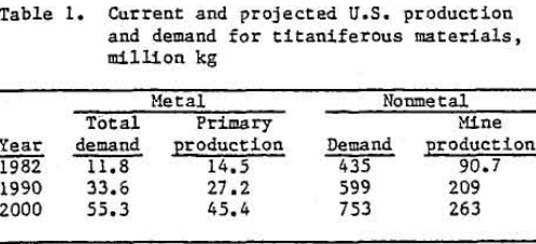
Table 1 shows a current and a predicted short-fall between U.S. titanium production and demand. Manufacture of titanium dioxide, primarily for paint pigments, accounts for 90 pct of domestic consumption of titanium raw materials.
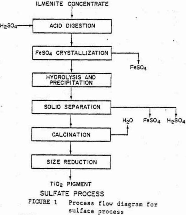
Plants using the sulfate process (fig, 1) treat ilmenite concentrate or titanium-rich smelter slag in sulfuric acid. In order to remove ferrous compounds and other impurities from the titanium oxides. This is followed by hydrolysis of titanium oxides, which are then calcined to TIO2. This process generates appreciable quantities of iron sulfate and spent acid wastes, which create serious pollution problems. The waste disposal problems have forced the closure of several domestic plants recently.
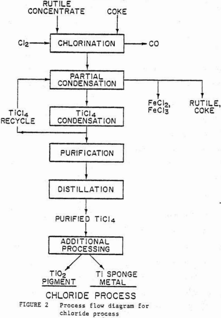
Newer chloride process plants manufacture about 65 pct of the domestically produced TiO2 and generate fewer waste problems than the older sulfate plants. The process is shown in figure 2 and is based on chlorination of titanium oxides to TiCl4. In a fluidized-bed reactor at temperatures of 1173 to 1373 ft, with a mixture of chlorine gas and coke. The TiCl4 is separated from other impurities, and the purified TiCl4 is either oxidized to TiO2 or reduced to titanium sponge metal with sodium or magnesium.
Although titanium-bearing minerals are found in sand and rock deposits throughout the world, the current demand for chlorination feedstock is primarily satisfied by two mineral sand concentrates. Rutile concentrates contain 95 wt pct TiO2, and ilmenite (primarily FeO·TiO2) concentrates contain more than 55 wt pet TiO2. Although the United States has large reserves of ilmenlte and other low-grade titaniferous rock minerals, these minerals contain oxide impurities that render them unsuitable for use as a chlorinator feedstock without further chemical processing.
Imported rutile, ilmenite, or titanium-enriched slags account for about two-thirds of the raw titanium requirements for the domestic manufacture of TiO2 paint pigments, welding-rod coatings, and titanium metal. Most natural and synthetic rutile, ilmenite, and titanium slag feedstocks are imported from Australia, the Republic of South Africa, and Taiwan (Lynd, 1983).
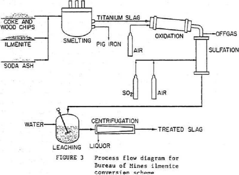
A simplified flow diagram is shown in figure 3 for a process developed at the Albany Research Center to prepare chlorination-grade feedstock from ilmenite. The titanium is separated from the iron by smelting the concentrate in an electric arc furnace. The high-titania slag then undergoes partial oxidation in a rotary kiln, followed by sulfation in a shaft reactor. Next, the reacted slag is leached with water, and the soluble sulfates are separated from the rutile by means of a continuous, solid-bowl centrifuge. The upgraded slag can then be chlorinated and TiCl4 recovered. The TiCl4 can be further processed into TiO2 for use in producing paint pigments or can be reduced to make titanium metal.
Smelting
Starting Materials
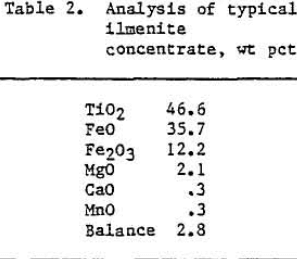
The ilmenite concentrate that was used in the test program was obtained from a rock deposit in New York. Chemical analysis of the concentrate is shown in table 2. A mixture of coke and woodchips was used as a reductant, and soda ash (Na2CO3) was used as a slag fluidizer.
Equipment
The smelting tests were performed in a stationary furnace with three graphite electrodes located in a delta configuration. The 907-kg- capacity furnace had a carbon brick lining in-stead of a conventional magnesite lining to prevent possible slag contamination with the furnace refractory. The experimental equipment used was identical to that used in previous Bureau studies (Nafziger, 1981). Figure 4 shows the furnace chat was used in the test program.
Operating Procedures
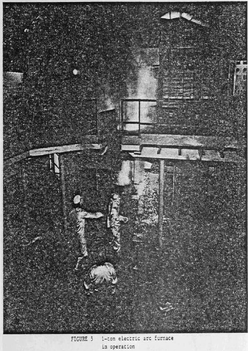
In commercial smelting of ilmenite, 10 to 13 wt pct FeO is left is the slag to preserve bath fluidity. Soda ash was added to the feed charge in the present tests during the smelting step to fluidize the slag. A target FeO concentration for this slag was approximately 5 wt pct FeO. The soda ash also served as a sulfation promoter for subsequent sulfation-leaching. A low-iron (less than 10 wt pct FeO) slag was necessary foe removal of MgO and MnO impurities in the oxidation-sulfation-leaching processes. Wood-chips were added to the feed charge as a reductant to insure uniform flow of charge material into the molten pool in the furnace and to increase charge porosity, which aids in the release of product gases. The furnace was started on the charge mixture without woodchips. As soon as a molten pool was formed, the furnace was filled with the charge mixture including woodchips. Metal and slag samples were taken during tapping; slag samples were taken on a regular basis in order to monitor FeO and Na2O content of the bath. The furnace is shown in operation in figure 5.
Results
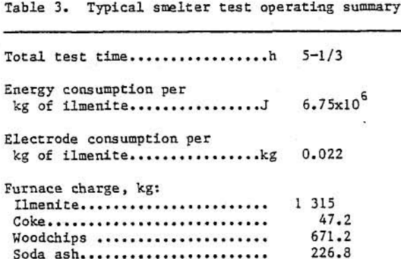
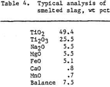
Approximately 7080 kg of ilmenite concentrate were smelted in six separate tests to yield 4000 kg of low-iron titaniferous slag. Table 3 shows some typical operating variables and results during a 907-kg smelting test. Table 4 contains a typical analysis of this titaniferous slag product. X-ray diffraction data indicated that the slag produced under the above operating conditions contained a pseudobrookite-type structure, a sodium titanium oxide phase (Na0.23TiO2), and a silicate-type glass. The pseudobrookite-type structure is illustrated below:
(Mn²+, Mg²+, Fe²+, Ti²+)0.2TiO2
and/or (Fe³+, Al³+, Ti³+)2O3.TiO2
Oxidation-Sulfation-Leaching
Chemical Reactions and Theoretical Considerations
Conversion of MgO and MnO impurities in the titaniferous slag to soluble sulfur oxide salts by chemical reaction with SO2 and O2 gases depends on oxidation of the pseudobrookite-type crystalline structure to rutile (TiO2> (Elger, 1976, 1981; Oden, 1973 ). The pseudobrookite type phase appears as black acicular crystals embedded in the glassy matrix. The Na2O and CaO impurities, which are not found in the pseudobrookite-type phase, are readily converted to soluble sulfur oxygen salts by chemical reaction. The pseudobrookite-type phase forms in titanium, slags during smelting and results in impurity substitution of Fe, Mg, Mn, and for divalent and trivalent titanium oxides. When Ti2O3 is oxidized to TiO2, the pseudobrookite-type structure is converted to rutile, which has a low solubility for these impurities.
Chemical reactions and thermodynamics involved in titanium slag sulfation-oxidation are difficult to analyze since Ca, Mg, Mn, Fe, Na, and Ti exist as complex compounds in solid solution with other materials rather than as simple oxides. The identity of these sulfation products and determination of their corresponding thermodynamic properties are beyond the scope of this research. The exact sulfur-oxygen salt that is formed during sulfation is undetermined. For the purpose of calculations, Ca, Mg, Mn, Fe, Na, and Ti were assumed to be either sulfates or oxides at their highest oxidation potential. Following are the chemical reactions that are thought to occur in the sulfation-oxidation pilot plant:
Sulfation reactions:
CaO + ½ O2 + SO2 → CaSO4
MgO + ½ O2 + SO2 → MgSO4
MnO + ½ O2 + SO2 → MnSO4
tia20 + ½ O2 + SO2 → Na2SO4
Oxidation reactions :
C + O2 → CO2
FeO + ¼ O2 → 1/2 Fe2O3
Ti2O3 + ½ O2 → 2TiO2
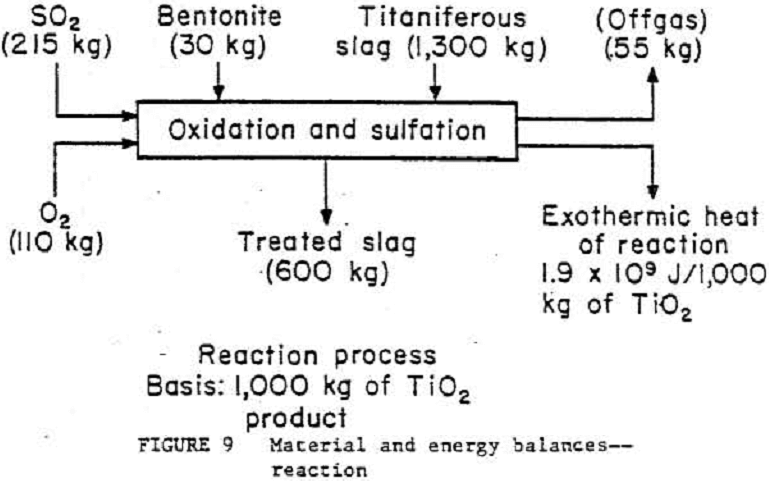
Gibbs energies for the above reactions at 973 to 1173 K show that the reactions are thermodynamically feasible. The total heat of reaction that is generated at these temperatures is highly exothermic, about 1.9 MJ/kg of reactant oxide. Approximately 40 pct of the total heat of reaction is generated by oxidation of C, FeO, and Ti2O3.
Equipment
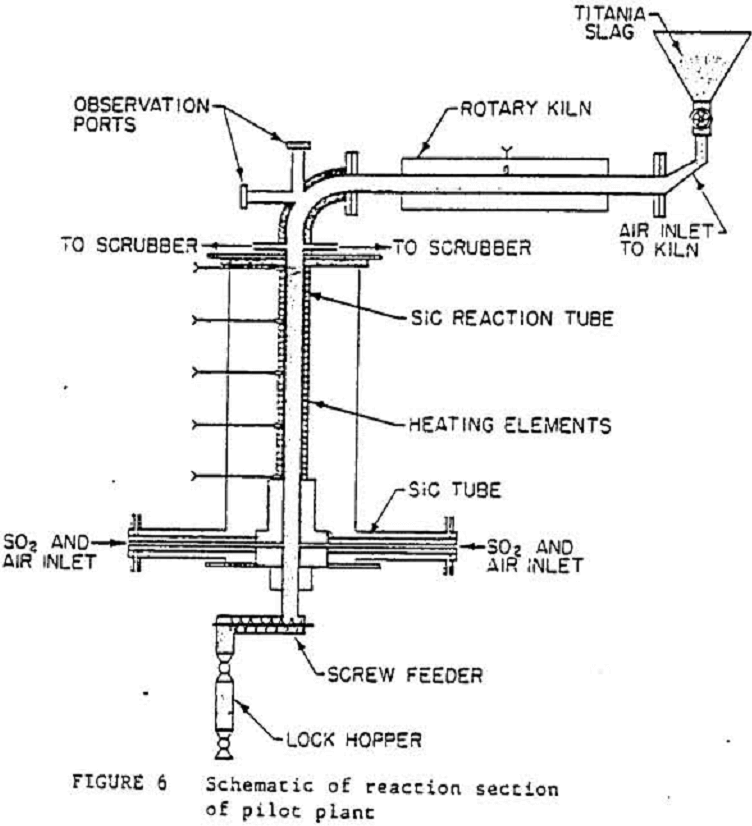
Figure 6 shows a detailed drawing of the pilot plant used in this work.
A laboratory pellet mill was used to convert the minus 35-mesh mixture of slag, bentonite, and water into 0.01-m-diam cylindrical pellets.
The oxidation kiln, which was horizontally oriented, consisted of a 1.52-m-long, 0.1-m-ID stainless steel tube rotating inside a 7.59-kW tube furnace. An alumina-lined elbow directed the slag to the vertical sulfation reactor.
As shown in figure 6, the vertical sulfation chamber consisted of a 1.6-m-long, 0.1-m-ID, 0.02-m-thick SiC tube that was held in place by ceramic castings. The 1.2-m-long, 18-kV heated section of the reactor was surrounded by auxiliary, electrically heated elements. The gas mixture entered the moving pellet bed below the heated section of the reactor. The entire assembly was surrounded by an insulated containment shell. A screw conveyor withdrew the sulfated pellets from the reactor and emptied them into a lock hopper. A scrubbing column was used to neutralize the offgases with an Na2CO3 solution. A continuous bowl centrifuge was used to separate the leached slag and the leach liquor containing the sulfated impurities.
Operating Procedures
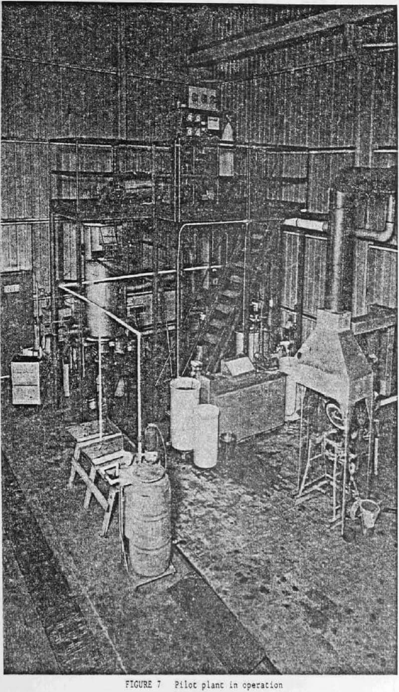
Figure 7 shows the pilot plant in operation.
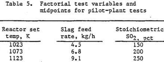
A test of the reaction system usually lasted 8 to 10 h. The SO2-air mixture was introduced into the system shortly after the kiln and reactor heaters were energized. Reactor upper and lower heater set-points ware adjusted to keep the mid-points of the heated areas below 1173 K. At slag flowrates of 4.5 kg/h, the pellets experienced approximately 4 h residence time in the heated zones. Product samples were taken every half- hour. Typical reactor system operating variables are shown in table 5.
The reacted titanium slag was leached in a stirred water solution, using a hatch process, in a 189-L tank. A 9.1 wt pct (10-to-1 water-to- slag ratio) slurry was leached in 2 h. The leached slag was available for further processing into TiO2 or Ti sponge metal.
Results
A two-level, three-variable, partial factorial experiment was conducted to determine the effects of slag feedrate, reactor set-point temperature, and amount of SO2 used, as compared with the assumed sulfation reactions stoichiometric requirements. The two levels are 1023 and 1123 K for reactor set temperature, 4.5 and 9.1 kg/h for slag feedrate, and 150 and 250 pct for gas flow-rate, as shown in table 5. A single test was conducted at the midpoints—1073 K, 6.8 kg/h, and 200 pet of stoichiometric SO2 requirement, (table 5), Because of material and time constraints, it was impossible to complete the number of tests required for a full factorial design, i.e., repetitions of identical run conditions were not made.
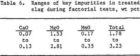
As can be seen from an examination of the data in table 6, the sulfation-oxidation-leaching operation yielded slags containing 0.07 to 0.13 wt pct CaO, 1.53 to 2.81 wt pct MgO, and 0.17 to 0.35 wt pct MnO, depending upon the experimental parameters used for each test.
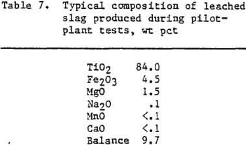
The MgO was by far the major troublesome impurity in the slag. Since the MgO level was cast affected by changes in experimental conditions, it was chosen as the dependent variable in the analysis. It was determined that at the 95 pct confidence level reactor temperature and amount of SO2 (within the confines of the variables tested) had negligible effects on the product MgO levels. The slag feedrate was significant. Decreasing the slag feedrate from 7.7 to 4.5 lb/h lowered the MgO levels by an average of approximately 0.9 wt pct. As shown in table 7, the slag was upgraded by reducing the total impurities (CaO, MgO, MnO) from 7.0 wt pct prior to treatment to an average of 1.7 wt pct after oxidation- sulfation-leaching.
Discussion
The removal of impurities from titaniferous slags can be a difficult task due to the location of these impurities within the slag phases matrix. The Ca impurity was located mainly in a glass phase, and its removal was relatively easy, but the Mg and Mn compounds were substituted within the pseudobrookite structure, caking their removal difficult. Analyses of the samples from each test showed that 90 wt pct or more CaO was removed, yet the best MgO and MnO removals were only 70 pct. The relative level of MnO followed the MgO level in the slag, although at a smaller magnitude.
The removal of MgO and MnO is difficult because of the pseudobrookite structure’s ability to take these impurities into a solid-solution series with iron and titanium oxides. Oxidation of the pseudobrookite structure to rutile results in the removal of these impurities, since rutile has a low solubility for MgO and MnO. Conversion of the pseudobrookite structure to rutile is best achieved with slags containing less than 5 wt pct FeO.
A primary concern was the determination of the affects of reaction some temperatures, reactant gas flowrates, and slag feedrates.
The sulfation temperatures reached during the pilot-plant tests were sometimes completely independent of the temperatures set into the instruments controlling the reaction zone heaters. These temperature buildups occurred because of the exothermic heat of reaction evolved during slag oxidation and sulfation. Temperature differences sometimes were in excess of 373 K between adjacent thermocouples, which were only 0.31 m apart in the sulfation reactor. Because of this nonuniform temperature throughout the reaction zone, it was not surprising that the reactor temperature was not a significant variable in the two-level factorial design.
Excessive heat buildup in the sulfation reactor could result in the closing of the pores of individual slag pellets. Thus, the reactant gases would not have been able to fully penetrate into the slag pellets. This would have caused the stopping of any further sulfation of the impurity compounds with the consequent impurity retention in the leached slag.
The second variable investigated was the flow-rate of SO2 used. Changing the flowrate to furnish between 150 and 250 pct of the theoretical SO2 requirement had negligible effect on increasing the removal of MgO and MnO. The effects of using greater flowrates (>250 pct of the theoretical requirement) have not been determined in the pilot plant.
The slag feedrate was the only variable of the three that had a definite effect on the product impurity levels. The longer residence time of the pellets at a feedrate of 4.5 kg/h in the reaction tone caused an increase in the amount of sulfation compared which a shorter residence time using a feedrate of 7.7 kg/h. Residence times in the 1,2-m reaction zone ranged from 150 to 97 min at the two extremes of slag flowrate.
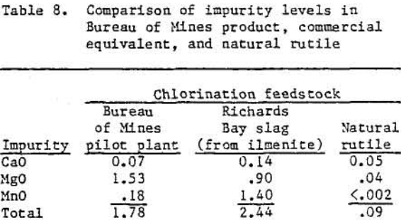
The bureau’s pretreated slag is comparable with other chlorination feedstocks, as can be seen from table 8. The rutile composition used comes from a National Stockpile Purchase Specification, which is used for metal production. The Richards Bay slag was obtained by smelting a sand ilmenite.
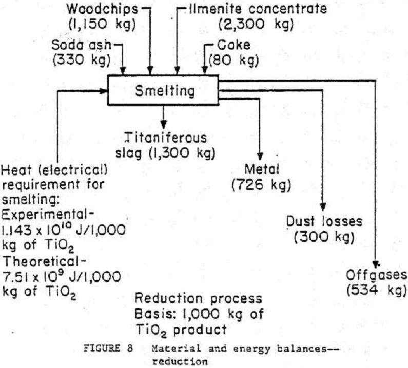
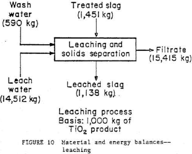
Material and Energy Balances
The ilmenite conversion process has been broken down into three general unit operations¬-reduction, smelting, and leaching—as shown in figures 8, 9, and 10. To see what actual flow-rates and energy requirements may be expected in a production plant, material and energy balance data from the 4.5- to 9.1-kg/h pilot plant were scaled to a basis of 1000 kg of TiO2 product. A typical commercial plant will produce around 136 000 kg/d of TiO2 product. Theoretical smelting energy requirements were calculated on the basis of pure ilmenite (FeO·TiO2) undergoing reduction at 1323 K. An accurate material balance based on the smelting step is impossible owing to a lack of exiting stream weight data. These exiting streams were calculated by individual component (TIO2, Ti2O3, FeO, etc.) material balances and by using exit stream component analyses. The leaching waste will be lime-neutralized, and the liquid then will be recycled back to the leaching seep. More research on liquid-solid ratios is needed before the leaching unit operation can be scaled to commercial size. Wash rates in the solid separation step were based on a rotary drum filter rather than a centrifuge, which was actually used in the test program.
Conclusions
The problem of exothermic heat buildup in the sulfation reactor may be solved both by oxidation of the titaniferous slag and by heat exchange between the incoming reactant gases and the reactor pellet bed. This would require introducing- gases at different locations along the reactor heated zone.
Pilot-plane tests demonstrated the Bureau’s pretreatment process effectively upgrades titanium slags made from a low-grade domestic ilmenite to a potential chiorination feedstock containing about 84 pct TiO2. Response of the slags to pretreatment by SO2 and O2 mixtures depends on FeO contents, reaction residence time, and use of a chemical additive to enhance impurity sulfation. Efficient removal of the Mg and an impurities is dependent on oxidation of the pseudobrookite-type phase to rutile.