
Table of Contents
The Federal Bureau of Mines has developed a flue gas desulfurization (FGD) process that uses a carboxylate solution, such as citric acid, to absorb sulfur dioxide (SO2) from industrial waste gases. The absorbed SO3 is subsequently reacted with hydrogen sulfide (H2S) to precipitate sulfur and regenerate the solution for recycle. This process is known as the citrate process and was developed as a result of research on the recovery of sulfur from gypsum. Briefly, the recovery of sulfur from gypsum involves reduction roasting of gypsum with coal or natural gas to form calcium sulfide. Subsequent processing of the calcium sulfide produces H2S, which is converted to elemental sulfur. In the laboratory, elemental sulfur was produced by reacting H2S with SO2 at ambient temperature in a liquid medium.
In 1968, the Bureau of Mines Salt Lake City (Utah) Metallurgy Research Center started research on FGD with emphasis on control of SO2 emissions from the nonferrous smelting industry. Initially, high-boiling organic liquids were tested as the medium for SO2 absorption and the sulfur-forming reaction as proposed in the patent literature. The relatively low SO2 absorption capacity and the high cost of pure organics led to the consideration of aqueous solutions as also proposed in the literature. Many reagents were screened for suitability. An aqueous solution of citric acid neutralized with soda ash to a pH of 4.5 was selected for further investigation because it best met the criteria desired of an absorbent solution. Among the factors affecting the choice of citrate were chemical stability, low vapor pressure, adequate pH buffering capacity, high water solubility, high SO2 loading capacity, ability to be regenerated easily and completely with H2S gas, and the purity and physical character of the precipitated sulfur. The initial laboratory research demonstrated the feasibility of removing SO2 from stack gas by absorption in a liquid medium and subsequent reduction of the SO2 to elemental sulfur in the same medium by reaction with H2S. This research was reported in 1970 and 1973. The Federal Clean Air Act of 1970 encouraged the Bureau of Mines to consider the citrate process for removal of sulfur from a variety of stack gases including those from nonferrous smelters, oil- and coal-fired electric and steam-generating plants, and oil and gas refineries.
Successful laboratory tests by the Bureau of Mines led to a pilot-plant project at the copper smelter in San Manuel, Ariz. The San Manuel pilot plant was constructed and operated jointly by Magma Copper Co. and the Bureau of Mines. This plant treated 300 scfm of copper reverberatory flue gas containing 1.0 to 1.5 vol-pct SO2 , and resulted in SO2 removal efficiencies from 90 to 99 pct. However, mechanical problems and intermittent operation prevented a complete evaluation of the process. The operation of the San Manuel pilot plant was reported in 1971 and 1973.
The major problem in the operation of the San Manuel plant was the separation of precipitated sulfur from citrate solution by thickening, centrifuging, and melting. Subsequently, a new method of sulfur separation by hydrocarbon flotation and melting was developed in the laboratory.
After the encouraging preliminary results, two new pilot-plant projects were undertaken. The purpose of these projects was integrating sulfur flotation, other process improvements , and some modifications to obtain data for engineering evaluation. One pilot plant using the citrate process was operated at a Pfizer, Inc., coal-fired steam-generating station near Terre Haute, Ind. This plant was built and operated by a private industrial group consisting of Arthur G. McKee and Co., Peabody Engineered Systems, and Pfizer, Inc.
It processed 2,000 scfm of flue gas having an average SO2 concentration of 1,000 ppm by volume. Sulfur dioxide removal efficiencies in excess of 95 pct were reported. The other project, a Bureau of Mines second generation pilot plant, was located at the Bunker Hill Co.’s lead smelter in Kellogg Idaho. At that smelter, lead concentrates are sintered in a Lurgi updraft sintering machine. Strong and weak SO2 gases are emitted from the sintering operation. The strong gas containing from 4 to 5 vol-pct SO2 is sent to a contact sulfuric acid plant for SO2 recovery. The weak gas containing from 0.5 to 1 vol-pct SO2 is filtered in a baghouse and vented through a stack to the atmosphere. In an effort to improve air quality, the Bunker Hill Co. expressed interest in testing the citrate process on the sintering machine gas At the same time, the Bureau of Mines needed an industrial cooperator to further develop the citrate process. On October 2, 1972, the Bunker Hill Co. and the Bureau of Mines executed a cooperative agreement to pilot-test the citrate process at the Bunker Hill lead smelter.
The Bunker Hill Citrate-Process Pilot Plant
General Process Description
The following process steps are shown in figure 1 which is a simplified flowsheet of the citrate process after modifications that evolved from both laboratory and pilot-plant testing:
- The SO2-bearing gas is cooled to between 113° and 149° F and cleaned of sulfuric acid (H2SO4) mist and solid particles.
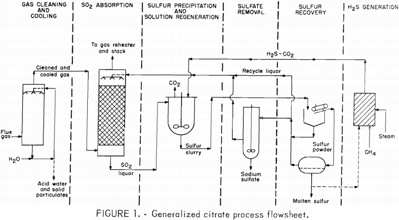
- The SO2 is absorbed from the cooled and cleaned gas by a solution of sodium citrate, citric acid, and sodium thiosulfate.
- Absorbed SO2 is reacted with H2S at about 149° F and atmospheric pressure to precipitate elemental sulfur and regenerate the solution for recycle.
- Sulfate is removed from a slipstream of regenerated recycle citrate solution by cooling the solution and crystallizing glauber’s salt (Na2SO4·10H2O), which is removed by filtration and then washed.
- Sulfur is separated from the solution by oil or air flotation and melting.
- The H2S for step 3, if not otherwise available, is made by reacting two-thirds of the recovered sulfur with natural gas (CH4) and steam.
Process Chemistry
Three steps of the citrate process include the following chemical operations:
- Absorption of SO2 in a buffered citric acid solution.
- Reaction of sulfur, CH4 , and steam to produce H2S.
- Reaction of the dissolved SO2 with H2S to produce sulfur.
The absorption of SO2 in water may be expressed as follows:
SO2 + H2O ↔ H+ + HSO3…………………………………..(1)
The salt of a weak acid (buffer) such as sodium citrate, glycolate, or maleate dissolved in the system reacts accordingly
H+ + HSO3 + Na+ + glycolate- ↔ Na+ + HSO3 + glycolic acid………………(2)
The hydrogen ion produced by absorption of SO2 in reaction 1 combines with a glycolate ion in reaction 2, to form glycolic acid, an un-ionized acid. This increases the capacity of the solution for SO2 absorption. The effect of SO2 loading on solution pH for three buffer concentrations is shown in figure 2.
H. W. F. Wackenroder investigated the reaction between H2S and SO2 in H2O in 1847. The chemistry of these reactions is complex. Polythionic acids and thiosulfate ion, as well as sulfur may be formed. The stoichiometry is usually expressed as follows:
SO2 + 2HgS → 3S + 2H2O…………………………………………(3)
This reaction does not proceed to elemental sulfur above pH 6. The reaction is favored by a low pH. However, below pH 3 the sulfur tends to be colloidal.
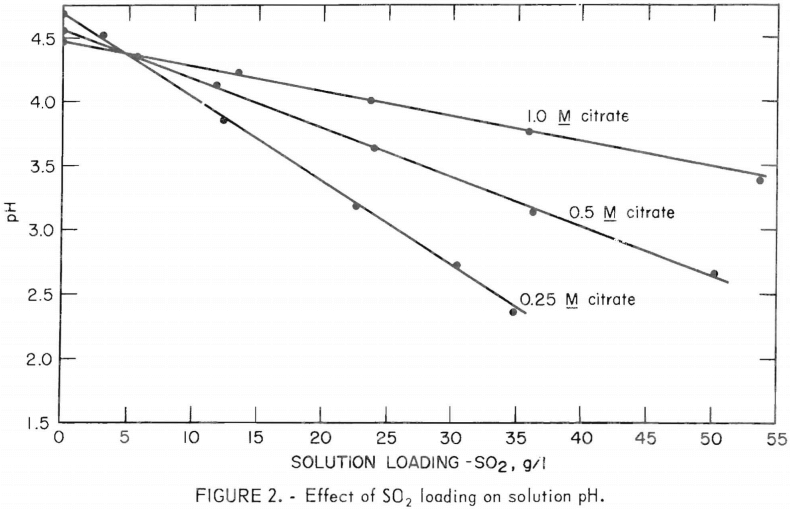
Half-molar citric acid solution buffered with a sodium base to a pH between 4.5 to 4.7 is satisfactory for the reactions 1-3. During SO2 absorption, the solution pH decreases as illustrated in figure 2. When the SO2 has been reduced to sulfur, the solution pH returns to the starting value prior to SO2 absorption. Thus, pH is one indicator of the degree of regeneration. However, sulfuric acid is formed by oxidation of SO2 to SO3 in the solution and by absorption of SO3 from the waste gas, Thus, base must be added to maintain the pH of the buffer because H2S will not reduce sulfuric acid. Eventually sodium sulfate must be removed to prevent crystallisation in the process. Sodium thiosulfate inhibits the oxidation of SO2 to SO3 . However, the pH of the buffer should be maintained around 4.5 because thiosulfate will decompose with acid and contribute to the sulfate problem.
The regeneration temperature was chosen to be 149° F for the following reasons: (1) The regenerated liquor would carry sufficient heat to the kerosine flotation section for satisfactory sulfur recovery, (2) it did not require excessive heating or cooling between regeneration and absorption, and (3) in laboratory studies the reaction was about 30 pct faster at 149° F than at 113° F
The hydrogen sulfide for reaction 3 was produced by two modes at the Bunker Hill plant.
Natural gas (CH4) was reacted with sulfur vapors at 1,202° F (16) over a proprietary catalyst
CH4 + 4S → CS2 + 2H2S……………………………………….(4)
The carbon disulfide (CS2) in the product was hydrolized with steam in a second stage at 608° F,
2H2S + CS2 + 2H2O → 4H2S + CO2……………………………….(5)
The final product was about 80 dry-vol-pct H2S and 20 dry-vol-pct CO2 .
A small amount of undesirable carbonyl sulfide (COS) may be present,
CS2 + H2O → COS + H2S………………………………………(6)
In the second mode, reactions 4-5 were effected simultaneously in one reactor as shown (3),
CH4 + 4S + 2H2O → 4H2S + CO2…………………………..(7)
The reaction is exothermic. Ten kilocalories per gram mole of H2S is produced at 40 psi and 1,202° F.
Absorption of SO2 was monitored and controlled by an “in-line” commercial SO2 analyzer on the feed and offgas streams. Also, SO2 in the scrubber solution was determined by standard iodometric titration.
Gas chromatography was used to determine the H2S content of the feed and offgas streams in the regeneration reactors. Iodometric titration for SO2 and thiosulfate , plus pH measurements were used to follow regeneration of the SO2-loaded solution.
H2S generation was controlled by gas chromatographic analyses for H2S, CO2 , COS, and CH4.
Design and Construction
The Bunker Hill pilot-plant design was based on the 300-scfm pilot plant at Magma Copper Co. and laboratory investigations. Contracts to design, fabricate , and install the plant were awarded to Morrison-Knudsen Co., Inc. , of Boise , Idaho. A major subcontractor, Home Oil Co., Ltd., of Canada designed the H2S generator section. This plant was designed to treat 1,000 to 1,500 scfm (60° F and 1 atm) of 0.5 vol-pct SO2 from either one of two possible sources —either acid plant feed gas diluted with air approximately eightfold or weak gas from the lead smelter sintering machine that was reported to be about 0.9 vol-pct SO2.
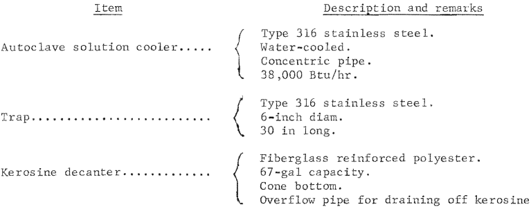
Generally, only materials known to resist the corrosive effects of the SO2-loaded gas and liquid streams were used in the plant. Fiberglass reinforced polyester (FRP) , polyvinyl chloride (PVC), or bitumen-lined carbon steel were used to fabricate process piping and vessels where temperature permitted. Type 316 stainless steel was used where high temperature or structural strength were factors. Carbon steel was used where the gas temperatures were above the sulfuric acid (H2SO4) dewpoint. The H2S generator process piping and vessels were all fabricated from suitable stainless steels because of high temperature and corrosive effects of feedstocks and products.
The Bunker Hill pilot plant was constructed in the following three phases:
Phase 1. SO2 absorption, solution regeneration, and sulfur recovery section.
Phase 2. H2S generator section.
Phase 3. Flue gas cooling and cleaning section.
Phase 1 of the project was constructed between March and December 1973, and acceptance testing began on January 9, 1974. The plant operated on H2S from a 13-ton-capacity tank trailer during construction and operational check-out of the H2S generator section. Construction of Phase 2 was started in December 1973, and after some design modifications the H2S generator was ready for acceptance testing in April 1975. Phase 3 of the pilot plant was constructed during 1974. It was brought on-stream to supply a cool and clean lead sintering machine dilute gas to the absorber in January 1975. By the end of April 1975, the completed plant was in operation and the tank trailer of H2S was no longer needed. Appendix A contains photographs of most of the essential items of equipment contained in the citrate process pilot plant. Appendix B lists the major items of process equipment.
https://www.youtube.com/watch?v=zDxhta3ER0c
Pilot-Plant Description and Operation
The block diagram in figure 3 shows the process when all three sections of the plant were operating. Variations from figure 3, which would be required in a full-scale plant, and recommendations based on pilot-plant operation, are discussed as the different process steps are considered. Figure 3 is a simplification of and a basis for the detailed process flow diagram and the material balance given in appendix C. The Bunker Hill pilot plant began operation in January 1974, logged over 5,400 hr, and produced about 55 net short tons of sulfur until completion of testing in May 1976. During that time, the H2S generator was operated to supply H2S gas to the citrate process for 3,090 hr. The gas cooling and cleaning section was operated as needed to test the respective components and to provide cool, clean, humidified gas to the SO2 absorption section. Appendix D gives a complete summary of the total operating time and downtime.
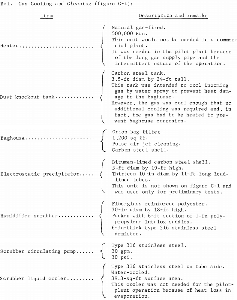
Gas Cooling and Cleaning
The SO2 absorption, solution regeneration, and sulfur recovery section of the pilot plant operated for about 1 year starting in January 1974, on a pre-cleaned sulfuric acid plant feed gas diluted about 8:1 with air to obtain the required 0.5 vol-pct SO2 feed gas. After installation and acceptance of the
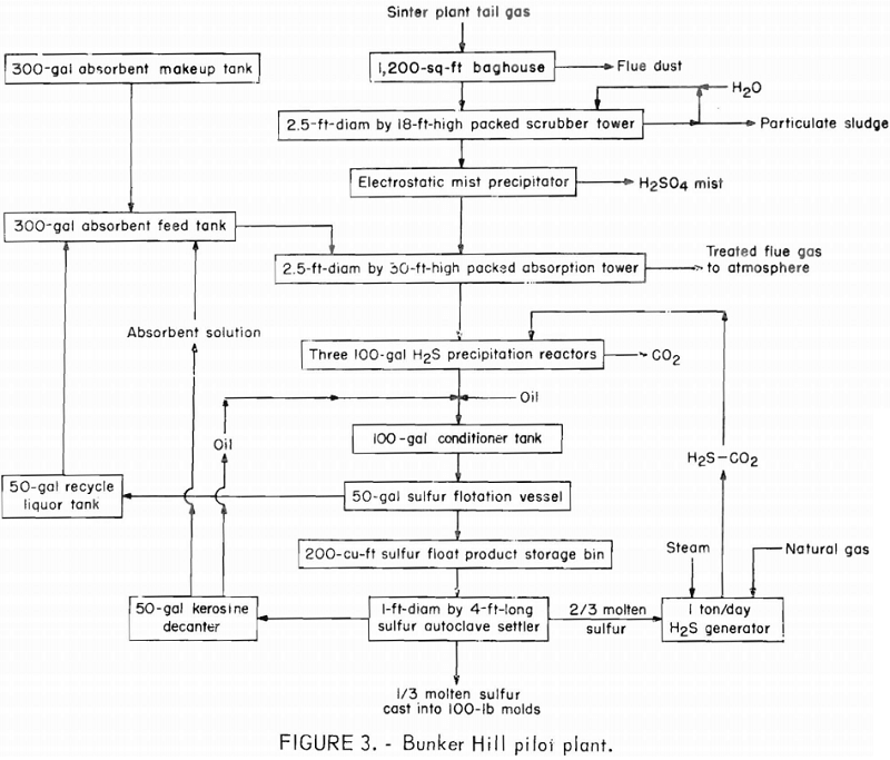
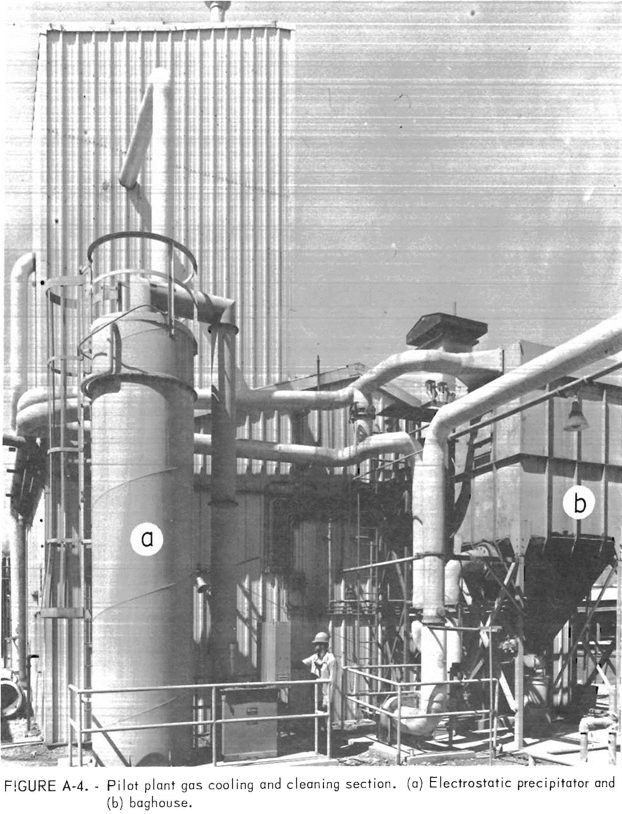
gas cooling and cleaning section, shown in illustrations A-2 and A-4, the source of the pilot-plant feed gas was switched to the weak gas from the Bunker Hill Co.’s lead smelter sintering machine. An induced draft fan was used to move the gas through the gas cooling and cleaning section and into the SO2 absorber. The weak gas flow was controlled by a valve located at the main weak gas duct and was drawn through about 150 ft of 10-in insulated carbon steel pipeline to the first unit in the pilot plant, a 3.5-ft-diam by 24-ft- high dust knockout tank that was originally intended to cool and condition the weak gas with a water spray for subsequent sulfuric acid mist removal. However, the weak gas temperature averaged only 266° F and heat losses from the weak gas pipeline and dust knockout tank were such that the weak gas had to be heated to prevent acid mist condensation and corrosion of carbon steel pipe-lines and process equipment. A natural gas-fired preheater was installed in a branch pipeline before the dust knockout tank to heat the weak gas. The weak gas also proved to be higher in SO2 than was reported and more variable in concentration, thus it was necessary to dilute weak gas with air and combustion gas to achieve on average 0.5 vol-pct SO2 feed gas for the pilot plant. Some of the SO2 fluctuation was reduced by adjusting the valve at the weak gas duct takeoff point. As the valve was closed, more dilution air was drawn in at the gas preheater.
The next unit in the gas cooling and cleaning section was a carbon steel baghouse containing 1,200 sq ft of Orion bags that were periodically cleaned by a pulsed air jet. The gas-fired preheater was automatically controlled to keep the baghouse inlet temperature at about 248° F. The baghouse dust hopper was periodically discharged to remove accumulated dust and determine dust loading in the weak gas. The baghouse dust removal efficiency averaged 99.6 pct resulting in an exit gas dust loading of about 0.26 mg/cu ft when the inlet gas contained 65 mg/cu ft.
The baghouse was backed by a 2.5-ft-diam by 18-ft prescrubber tower constructed of FRP and packed with a 6-ft bed of 1-in polypropylene Intalox saddles. This prescrubber removed about 95 pct of the remaining dust in the gas, resulting in exit gas containing about 0.013 mg/cu ft. Also, the prescrubber removed about 91 pct of the sulfur trioxide (SO3) from a prescrubber inlet gas containing 0.23 mg SO3 per cubic foot, resulting in an outlet gas containing about 0.02 mg SO3 per cubic foot. The countercurrent scrubber solution flow was 25 gal/min. A small purge flow of about 0.2 gal/min was maintained to keep the solution pH above 1.5 and avoid solids buildup. A level controlled solenoid valve replaced the purge with plant water. This purge joined other neutralized wastes from the smelter acid plant. In a full-scale plant this acid waste would have to be neutralized with lime or limestone and ponded to prevent contamination of water supplies.
The prescrubber tower was used for all operations except for a 1-month test. During this test, the sulfate accumulation increased slightly from about 1.2 to 1.4 wt-pct. However, this was not considered significant. There was no other noticeable effect on the rest of the pilot-plant operation.
Although operation without the prescrubber caused no problems at the Bunker Hill pilot plant, it was a special situation because of the low gas temperature and high efficiency of the bag filter. In a commercial installation it is expected that a baghouse or a dry electrostatic precipitator followed by a wet prescrubber would be the minimum requirement for gas cooling and cleaning. The presence of SO3 mist in the gas may also require a wet electrostatic mist precipitator following a wet prescrubber. A commercial plant would also require a cooler for the circulating dilute sulfuric acid to the prescrubber. Although such a cooler was installed in the pilot plant, it was never used.
The induced draft fan was installed downstream of the prescrubber. The fan impeller was fabricated of type 316 stainless steel and the fan casing was fabricated of cast iron and coated with Bisonite. Although the location of the induced draft fan at the pilot plant was satisfactory, some corrosion of the Bisonite-coated casing did occur. A better fan location would have been downstream of the baghouse where most particulates had been removed but the gas temperature was still hot enough to prevent acid condensation and corrosion. By moving this fan the need for corrosion-resistant alloy construction or casing lining would be eliminated.
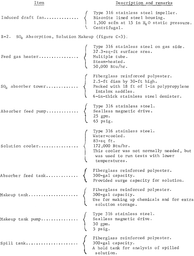
Finally, to control the temperature of the SO2 absorber tower for testing and process evaluation, it was necessary to humidify and heat the gas after leaving the prescrubber. This was done by adding steam directly and then passing the gas through a shell and tube steam heat exchanger to achieve enough superheat to prevent condensation in the gas flowmeter. This ability to humidify and heat the gas permitted evaporation and temperature control in the SO2 absorber.
SO2 Absorption
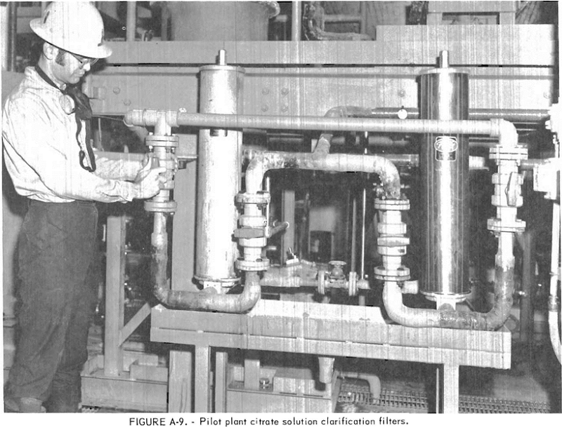
The main unit in the SO2 absorption section of the pilot plant was a 2.5-ft-diam by 30-ft-high absorber tower. This tower was constructed of FRP and was packed with 18 ft of 1-in polypropylene Intalox saddles. Entrainment of absorber solution in the gas was controlled by a type 316 stainless steel mesh demister in the top of the tower. The absorber solution was pumped to a distributor above the packing by a sealless magnetic drive pump at rates ranging from 5 to 15 gal/min. The solution was clarified by a dual backwash, porous type 316 stainless steel filter having a surface area of about 6 sq ft. The solution was cooled with water, when necessary, by a type 316 stainless steel shell and tube heat exchanger. The solution flow was measured by a float-type flowmeter and automatically controlled to the desired flow-usually 10 gal/min.
Among the conditions varied in the pilot-plant tests were type and concentration of the absorbent solution, liquid flow rate and resultant SO2 loading, feed gas SO2 concentration and flow rate, and feed gas and solution temperatures. Operation of the absorber was generally satisfactory and trouble-free. Some problems did occur in the auxiliary system, however. The most troublesome of these were blinding of the clarification filters and plugging of the transfer pumps. This was due to upsets in the sulfur recovery section, which at times allowed more sulfur to carryover with the solution than could be handled by the filters. Blinding of the filters also occurred when too much kerosine was used in the flotation step and allowed to get into the filters. These problems were minimized when the solution regeneration and sulfur recovery sections were operating properly. The normal amount of sulfur carryover (less than 1 pct of the sulfur float product) was handled by occasional backwashing of the filters. The backwash sulfur slurry was returned to the conditioner tank in the sulfur recovery section of the pilot plant.
SO2 Absorption Results
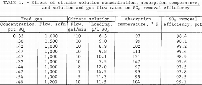
The results of operating tests listed in appendix 1 are summarized in tables 1-4. Table 1 shows the effect of citrate solution concentration, absorption temperature, and solution and gas flow rates on the SO2 removal efficiency. The SO2 removal efficiencies were based on feed and offgas analyses . The tests were made using pure H2S to regenerate the solution in a single 100-gal reactor operating at an agitator speed of 220 rpm and a temperature of about 149° F. Citrate solution concentrations of 0.25 M and 0.5 M were tested. The absorption temperature was varied from 95° to 147° F. The solution and feed gas flow rates were varied from 5 to 10 gal/min and from 1,000 to 1,500 scfm, respectively. The concentration of SO2 ranged from 0.30 to 0.54 vol-pct, the regenerated solution pH ranged from 4.2 to 4.7, and the solution SO2 loadings ranged from 6.3 to 21.3 g/l. These loadings represent from 50 pct up to 95 pct of the equilibrium loading values, which are shown in appendix F. Only in tests where the absorption temperature was 147° F or the solution flow rate was 5 gal/min did the absorption efficiency decrease to any extent. The design SO2 loading for the pilot plant was 10.8 g SO2 per liter when treating 1,000 scfm of 0.5 vol-pct SO2 gas with 10 gal/min of 0.5 M citrate solution at a temperature of 113° F. This design loading represents about 60 pct of the equilibrium loading. The test that came closest in loading and conditions to this design resulted in a 99.4-pct SO2 removal efficiency.
Although the pilot plant was designed to test SO2 feed gases in the 0.5-vol-pct SO2 range, a few tests were run with SO2 feed gas concentration of 0.10 vol-pct or less. Such a gas might be typical of the flue gas from a coal-burning powerplant firing medium sulfur content coal (1 to 2 pct sulfur).
Table 2 shows the effect of low SO2 feed gas compared with results using higher SO2 feed gas. All tests in table 2 were run using 78 dry-vol-pct H2S gas from the H2S generator to regenerate the solution in two 100-gal reactors operating at an agitator speed of 220 rpm and a temperature of about 149° F.
The citrate solution concentration was between 0.4 and 0.5 M. The most significant results of these tests was an SO2 loading of 4.1 g SO2 per liter, which represents 83 pct of the equilibrium loading value, and an SO2 removal efficiency of 95 pct. The results in table 2 show that the process is applicable to flue gases from coal-fired powerplants.
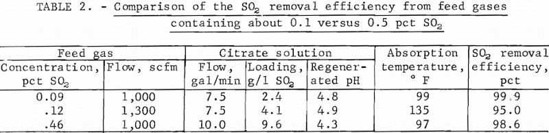
Table 3 shows the effect of H2S excess on the SO2 removal efficiency and pH of the regenerated solution. The term “H2S excess, pct” in table 3 means that the stoichiometric H2S feed rate plus the stated excess was fed to the solution regeneration section. Although this excess was lost to the incinerator, it raised the partial pressure of H2S in the reactors.
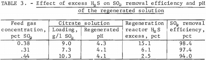
Tests were made using 78 dry-vol-pct H2S gas from the H2S generator to regenerate the solution in either two or three 100-gal reactors operating at an agitator speed of 220 rpm and a temperature of about 149° F. Ten gallons per minute solution flow was used and the solution concentration ranged from 0.45 to 0.60 M citrate. The absorption temperature was between 93° and 97° F. The flow rate of the feed gas, which was either lead smelter sintering machine weak gas or commercial SO2 containing from 0.31 to 0.44 vol-pct SO2, was about 1,100 scfm.
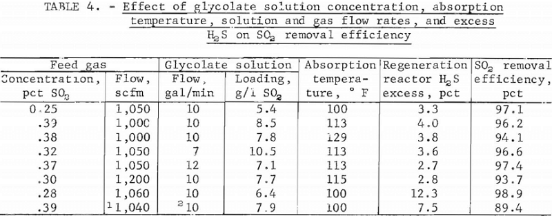
Table 4 shows the effect of solution concentration, absorption temperature, solution and gas flow rates, and excess H2S on the SO2 removal efficiency when using an absorbent made-up with glycolic acid instead of citric acid. Tests were made using 78 dry-vol-pct H2S to regenerate the solution in two 100-gal reactors operating at an agitator speed of 220 rpm. The regeneration reactor temperature was about 149° F. The flow rate of the feed gas, which was commercial SO2 except for one test on lead smelter sintering machine weak gas, was varied from 1,000 to 1,200 scfm and the feed gas concentration ranged from 0.25 to 0.39 vol-pct SO2. The solution flow rates were varied from 7 to 12 gal/min and the regenerated solution pH ranged from 4.1 to 4.6. The glycolate molarity, except for one test in which a 0.23 M glycolate was used, was between 0.8 and 0.9 M. The results shown in table 4 confirm two important process parameters:
- Glycolate solution may be substituted for citrate solution.
- From 3 to 4 pct excess H2S is required for efficient operation.
SO2 Absorption Rates
The overall mass transfer coefficient, Kg a, is often used to express gas absorption rates. The Kg a value for the absorption of SO2 in citrate solution may be used to design gas absorption equipment of a different size to do the same job. The coefficients usually have the units of pound moles of SO2 absorbed per hour per volume of absorber packing per atmosphere driving force and are corrected for atmospheric pressure. A few mass transfer, coefficients for tests at the Bunker Hill pilot plant are shown in table 5. The method for calculation is outlined in the following discussion.
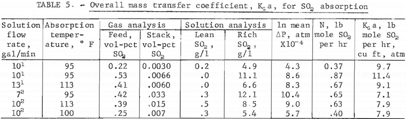
The first requirement is an equilibrium SO2 loading curve for the temperature, pressure, and the solution concentration being used. These curves are shown in appendix F. Interpolation and pressure correction is necessary if the conditions of the test vary from conditions for which the curves were made.
For the Kg a values given in table 5, the citrate solution concentrations were 0.5 M citric acid, 1.0 M caustic soda, and about 0.25 M thiosulfate. The glycolate solution concentrations were 0.9 M glycolic acid, 0.8 M caustic soda, and about 0.25 M thiosulfate. As stated previously, the absorption tower packing height was 18 ft. The absorption tower cross section area was 4.91 sq ft. The atmospheric pressure at the Bunker Hill pilot plant was 0.92 acm. The gas flow rate for all the examples given in table 5 was about 1,000 scfm.
The formula for calculation of Kg a as described in reference 5 is
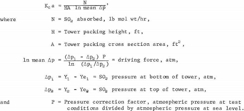
p1 and p2 are driving force factors; that is, the difference between actual SO2 concentration, Y1 , in the gas and the concentration at equilibrium, Ye1, (for the tower bottom) and Y2-Ye2 (for the tower top). Units used are atmospheres partial pressure of SO2. Usually, Ye2 is assumed to be zero since the solution going back to the tower top is completely regenerated.
In table 5, the average Kg a of 10.1 for citrate solution is greater than the 7.6 for the glycolate solution. However, this is not indicative that glycolate solution is less desirable than citrate because the molar concentration of glycolate used was lower in buffering capacity. In buffering capacity, 1.5 M glycolate is comparable with 0.5 M citrate.
Solution Regeneration
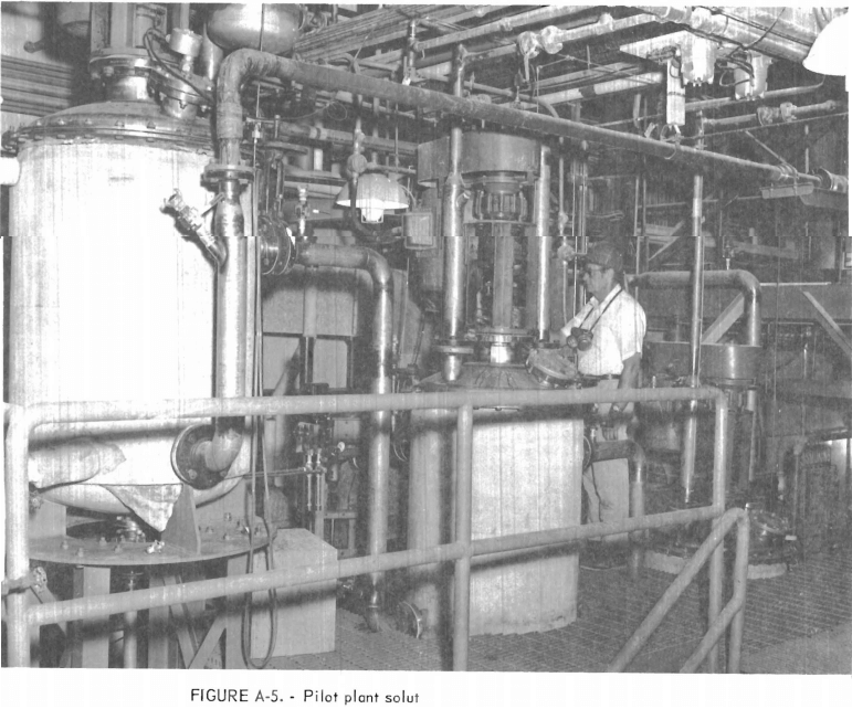
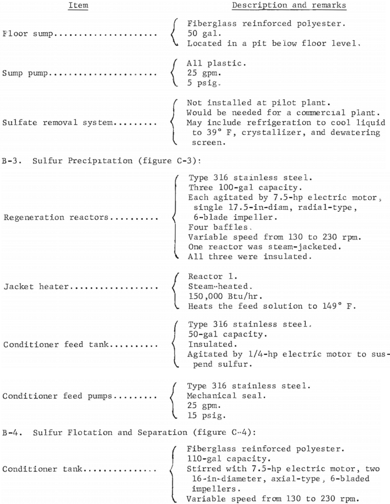
The solution regeneration section is shown in illustration A-5. It consisted of three 100-gal, baffled, type 316 stainless steel reactors. Each was stirred with a 17.5-in-diam, 6-blade radial turbine-type impeller. These variable-speed agitators were capable of 230 rpm and a tip speed of 1,050 ft/min.
The first reactor was fed by gravity through a variable level control and siphon breaker from the absorber tower bottom. The three reactors were cascaded for gravity flow of sulfur slurry. The H2S could be fed into any of the three reactors countercurrent to the flow of slurry and was introduced under the reactor impeller through an open 3-in pipe. Reactor 1 was steam-jacketed for temperature control. The other reactors were insulated to conserve heat.
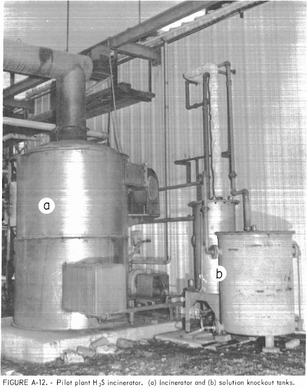
When using one reactor and pure H2S, H2S was supplied on a demand basis. That is, the H2S supply system was automatically controlled to maintain 0.5 lb/sq in of H2S pressure over the solution. This mode of operation did not waste H2S. However, at startup, it was necessary to vent the reactor to displace the air from the system to an H2S incinerator shown in illustration A-12.
When using H2S generator product (78 pct H2S), the H2S requirement was determined by following the degree of solution regeneration and analyzing the reactor offgas for H2S. During operation, it was necessary to vent the reactor to displace the CO2 and unreacted H2S from the system to the H2S incinerator.
Table 6 presents some typical regeneration data with glycolate and citrate scrubbing solutions. Agitation was the same in all tests, 1,050 ft/min impeller tip speed. The SO2 loadings are concentrations in the reactor feed. They are not steady-state SO2 concentrations in the reactors. The final reactor effluent solutions averaged less than 0.5 g of SO2 per liter. The pH of the loaded solutions in these tests averaged 4.4 for the glycolate and citrate solutions. These solutions also contained 0.25 M Na2S2O3.
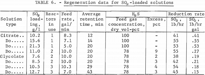
The data indicate that 100 gal of reactor volume are sufficient to treat 50 lb of SO2 per hour with pure H2S. With 78 pct H2S, 200 gal of reactor volume were required. Glycolate scrubber solutions regenerated as readily as the citrate solutions. Therefore, glycolate was assumed to be a satisfactory scrubber solution for the process.
One of the most serious problems in this section of the plant was the formation of sulfur plugs in the gas vent lines and slurry lines between the reactors. Although this problem remained unsolved, these plugs were usually removed and flow restored by injecting steam at various points along the lines.
A second and less serious problem, from the operational standpoint, involved the presence of dissolved H2S and some colloidal sulfur in the regenerated solution. The H2S would evolve, from solution, in the sulfur flotation cell and contaminate the air. The colloidal sulfur could not be removed by flotation.
The problem was solved by injecting about 5 pct of the SO2-loaded solution from the absorption tower into the conditioner tank. This eliminated the excess H2S and dissolved the colloidal sulfur.
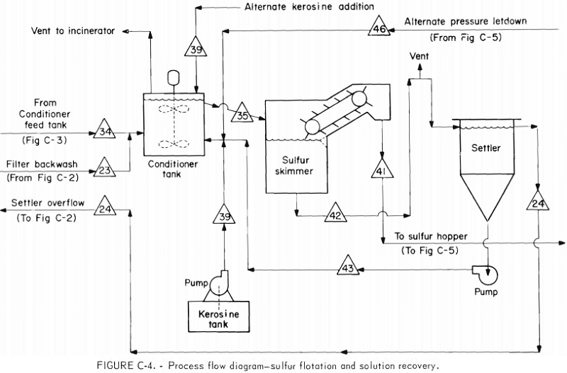
Sulfur Separation and Solution Recovery
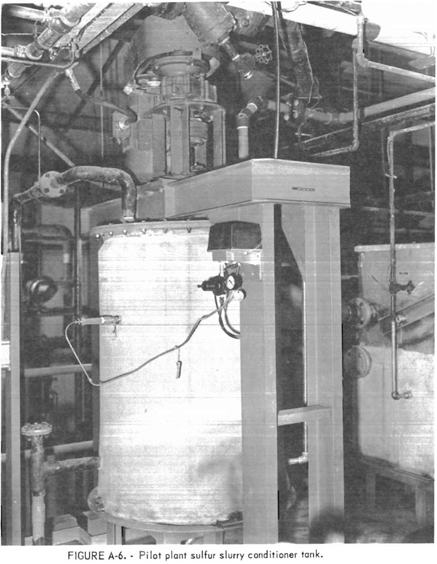
After the reactors, the regenerated solution containing about 1.5 pct sulfur overflowed to a 50-gal stirred, type 316 stainless steel conditioner feed tank. From this tank the sulfur slurry, at a temperature of about 127° F was pumped to a 100-gal FRP conditioner tank shown in illustration A-6. The conditioner tank was stirred by a variable-speed agitator equipped with two 16-in- diam axial impellers. The lower impeller mixed the hydrocarbon flotation reagent and the upper impeller, located just below the surface, broke up the accumulations of floating sulfur. The mixture of floating sulfur and regenerated solution overflowed through a 3-in-ID sloping line to the sulfur flotation vessel. An agitator tip speed of 700 ft/min was sufficient for good sulfur flotation.
By design, 6 to 12 g of kerosine per minute were added to the conditioner by a chemical feed pump. This quantity of kerosine amounted to about 1 to 2 pct of the gross sulfur production. The average sulfur content of the float product was 48 pct solids under these conditions. Later the kerosine addition point was changed from the bottom of the conditioner tank to a point just above the overflow line. At the same time the kerosine feed pump was replaced with a smaller pump. These changes improved kerosine dispersion. The kerosine consumption using this new addition point was only about one-fifth of the previous requirement or 0.2 pct of the gross sulfur production. The percent solids of the float product was the same when using the new addition point and less kerosine.
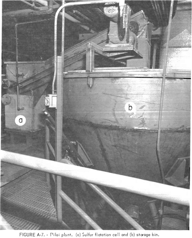
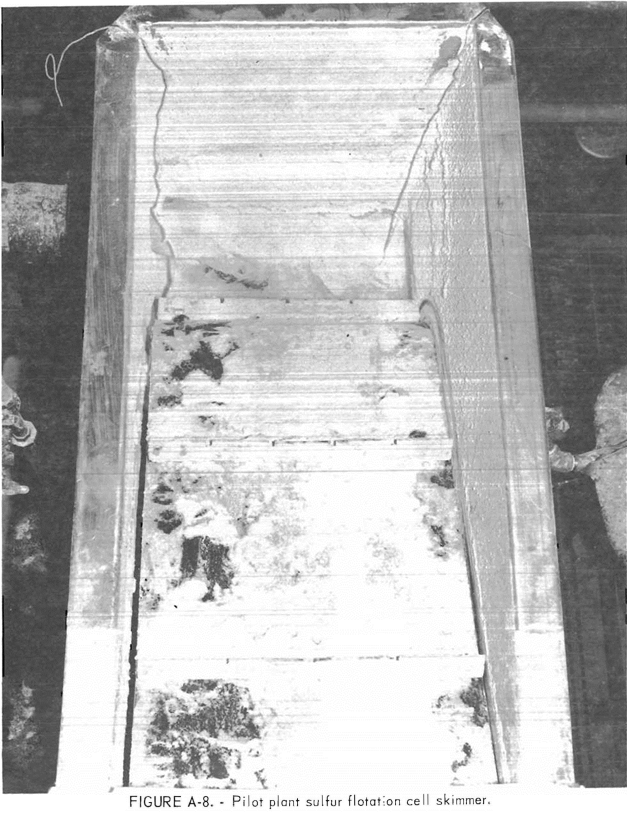
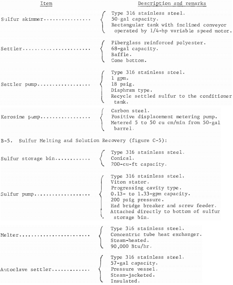
The sulfur flotation vessel was a 50-gal-capacity, rectangular, type 316 stainless steel tank with a bottom outlet and an inclined chute with a drag-type belt conveyor shown in illustration A-7. The sulfur, in the form of 40 to 50 pct solids powder, floated on top of the vessel and was continuously skimmed off by the blades of the conveyor shown in illustration A-8. The end of the conveyor discharged into a 200-cu-ft capacity, type 316 stainless steel storage bin. The clear solution flowed from the bottom of the sulfur flotation vessel through a level controller into a 65-gal-capacity cone bottom FRP settler tank. Here, a small amount of sulfur that failed to float (usually less than 1 pct) was settled and recycled to the conditioner tank by a slurry pump. A vertical baffle in the settler tank separated a small amount of floating sulfur that escaped from the sulfur flotation vessel. This floating sulfur was periodically removed manually and added to the sulfur storage bin. The carryover of floating and sinking sulfur indicated deficiencies in the design of the sulfur flotation circuit. The clarified solution, after leaving the settler tank, overflowed by gravity into a 300-gal capacity FRP absorber feed tank, thus, completing the cycle for the mainstream of absorbent solution.
Flotation of sulfur with air , alone (no addition of kerosine to the conditioner) was tried because it resulted in improved product sulfur purity. Sulfur produced with air flotation contained 0.04 pct carbon, but that produced with kerosine flotation contained 0.15 pct carbon. Flotation with air also reduced reagent costs and eliminated the need for a kerosine recovery system. The flotation of sulfur with air involved the addition of 5 to 10 liters of air per minute through a porous stainless steel diffuser tube located in the bottom of the sulfur flotation vessel. The sulfur pickup conveyor worked just as well as with oil-floated sulfur and the clarity of the underflow solution was also very good. However, the percent solids of the separated sulfur was from 8 to 20 pct. Assuming an average percent solids of 14, the weight of solution that would have to be heated in the process of melting sulfur is increased by about six times. The cost of the additional heat, plus the decomposition of citrate and formation of sulfate that occurs in the autoclave must be weighed against the advantages of the air-flotation method.
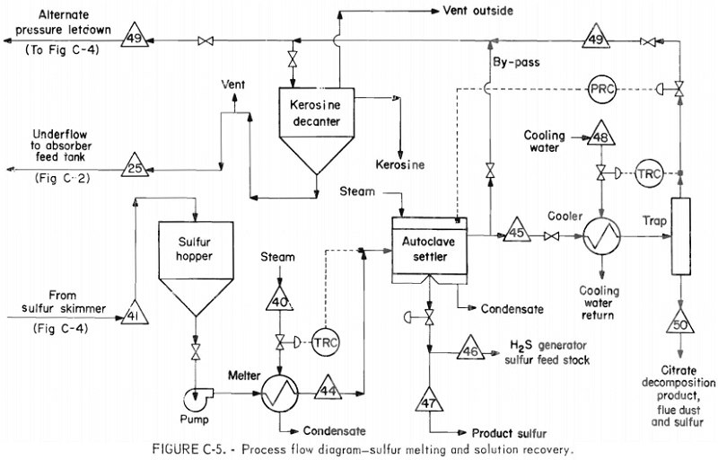
Sulfur Melting and Solution Recovery
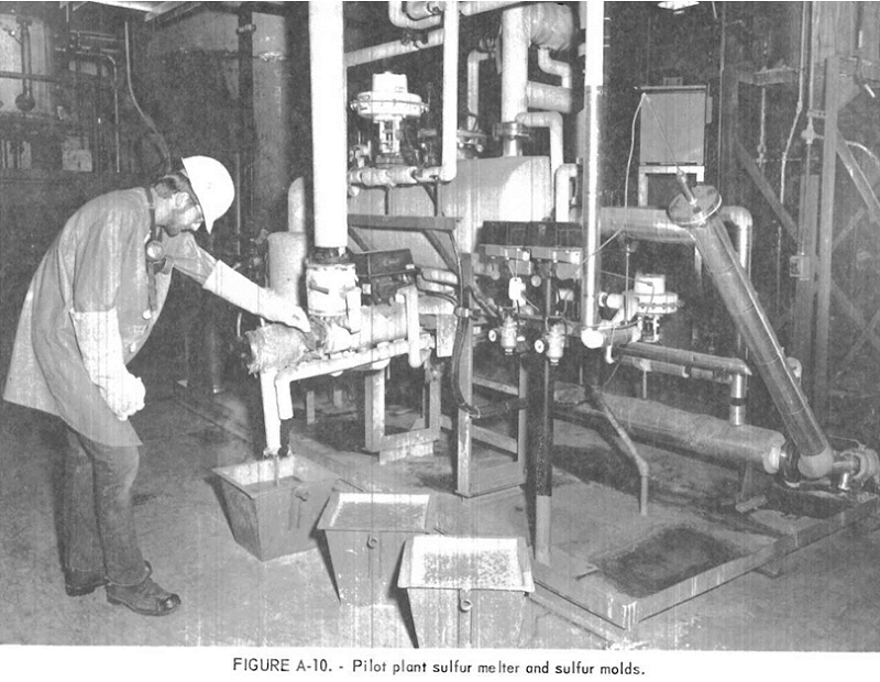
The sulfur melting was done during day shift only. The sulfur float product accumulated in the 200-cu-ft storage bin for the other 16 hr. This mode of operation allowed the use of a commercial-size progressing, cavity-type slurry pump for moving the sulfur into the melter. This pump was installed directly on the bottom of the storage bin and was fed through an 8-in gate valve into the bridge-breaker of the pump. Feed to the pump was aided by a bin vibrator and by a timed blast of air that discharged into the sulfur every 30 sec near the bottom of the bin to prevent bridging. Downstream of the pump, the sulfur was melted with steam at a rate of 300 to 400 lb/hr in a 14-sq-ft- area concentric tube heat exchanger. After exiting from the heat exchanger the melted sulfur was separated from the remaining absorbent solution in a 57-gal-capacity, type 316 stainless steel autoclave settler , shown in illustration A-10, operating at a pressure of about 35 psig, and a temperature of 284° F. The pressure in the heat exchanger and autoclave settler was controlled by automatic release of solution from the top of the autoclave settler, through a water-cooled concentric tube heat exchanger and a knockout pct into a 50-gal-capacity cone bottom FRP kerosine separator tank. The cooled solution was withdrawn from the bottom of this tank through a level controller and flowed by gravity to the absorber feed tank. Kerosine that floated to the surface was allowed to accumulate and then was periodically floated out through an overflow line to a tank for reuse. In practice, there was little recovery of kerosine when its usage was held below 1 pct of the gross sulfur produced because of vaporization losses. The kerosine dissolved in the sulfur was about 20 pct of the total kerosine based on carbon analysis of the sulfur product. No attempt was made to recover kerosine lost out of the tank vents because of the small amount involved—about 15 lb/day. However, some could be recovered by collecting and chilling the vent gases or bypassing them through a cold absorption tower.
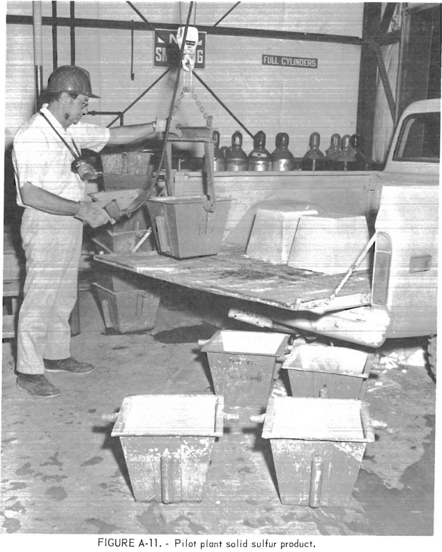
Sulfur withdrawal from the autoclave settler was accomplished by a steam-jacketed, automatic level control valve on the bottom of the settler. Two- thirds of the sulfur produced was transferred by pressure of the settler through steam-jacketed lines to the H2S generator sulfur storage tank where it was maintained as a molten liquid for use. The remaining sulfur was cast into 100-lb blocks and stored, as shown in illustrations A-10-A-11. Since the melting was only done for 8 hr out of the 24 hr, all sulfur was drained from the autoclave settler each day, leaving the autoclave settler free of sulfur and preventing the buildup of impurities that could have caused plugging of the drain valves. This mode of operation led to a small unaccounted loss of solution each time the autoclave settler was drained.
The sulfur melting operation required the close attention of an operator. The sulfur float product occasionally bridged in the bin and failed to pump. Also, the pressure letdown valve, lines, and solution cooler heat exchanger would plug due to kerosine-dissolved sulfur that crystallized upon cooling. This material analyzed about 91 pct sulfur, up to 1 pct lead and zinc, and smaller percentages of iron, copper, cadmium, silicon, and aluminum. The minor components are a carryover of flue dust into the system. Most of the material eventually ended up in the kerosine separator tank where it collected in the cone bottom, requiring cleanout of about 40 lb per month. An alternate route for pressure letdown from the autoclave settler was to the bottom of the conditioner tank. This route was used when the line to the kerosine separator tank became plugged and had to be cleaned. It also could be used to bypass the pressure letdown cooler and control valve when these needed cleaning. The plugging problem was minimized by operating with less kerosine for flotation and was largely eliminated when no kerosine was used.
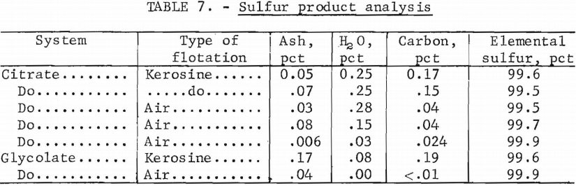
The product from the autoclave was high-purity, bright yellow sulfur, and it was used successfully for H2S generation. However, the carbon and other impurities combined with sulfur and formed a black flake-like material that caused sticking of the sulfur pump check valves. This condition caused loss of sulfur flow and frequent backflushing was required to keep the sulfur pumps operating. Probably a filter before these sulfur pumps would have solved this problem. Table 7 shows the quality of sulfur made with kerosine and with air flotation. As shown, the solution used—citrate or glycolate-had little effect on sulfur quality.
Solution Makeup
The absorbent solution was prepared in a 300-gal stirred FRP absorbent makeup tank. The ingredients and order of mixing for a 250-gal batch of 0.5 M citrate solution were as follows: water, 150 gal; citric acid, 200 lb; soda ash, 100 lb; sodium thiosulfate, 128 lb; and water to final volume. The soda ash was added slowly to prevent boilover due to CO2 release and the thiosulfate was added last to prevent decomposition. About 1,000 gal were needed to fill the pilot-plant system. The drain lines of the two tanks, makeup and feed, were also interconnected to provide extra system surge capacity.
Chemical Usage—Inventories
 The important chemical makeup requirements for the SO2 absorption, solution regeneration, and sulfur recovery section of the pilot plant included citric or glycolic acid, sodium carbonate, and kerosine. The pilot plant was designed so that solution losses from spills, leaks, etc., could be collected in a common sump. The plant concrete floor was sloped to trenches which, in turn, drained into the sump. The sump pump was set to pump to a 300-gal stirred FRP spill tank where all spilled solution was measured and sampled for analysis before dumping to the chemical sewer. Any future plant should provide for the cleanup and recycle of known major spills of absorbent solution. Solution inventories and samples were taken at the end of operating periods (usually about every 2 weeks) and citric or glycolic acid losses were calculated.
The average of many citrate loss tests during runs when upsets or solution losses were minimized showed that about 20 lb of citric acid were lost per net ton of sulfur produced. The average glycolic acid consumption was less than 10 lb per net ton of sulfur. A sodium carbonate addition of about 90 lb per net ton of sulfur was required to neutralize sulfuric acid and to make up fresh citrate solution.
Toward the end of the pilot-plant operation the kerosine requirements were reduced to about 2 gal per net ton of sulfur produced.
H2S Generation
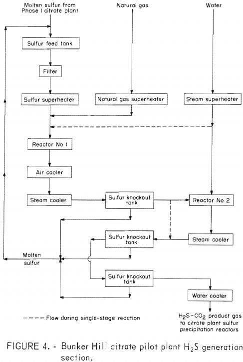
The H2S generator indicated as a single block in figure 3 is depicted in some detail in the flow diagram in figure 4. Solid lines in this diagram indicate flows for a two-stage reaction considered to be a proven process. The dashed lines indicate provision to bypass reactor 2 for later experimentation with a single-
stage reaction. The design capacity of the plant was 0.4 to 1.25 tons of H2S per day.
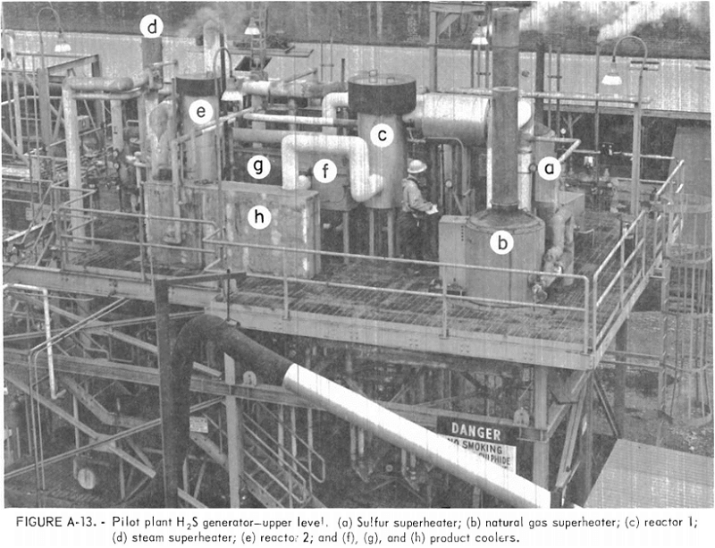
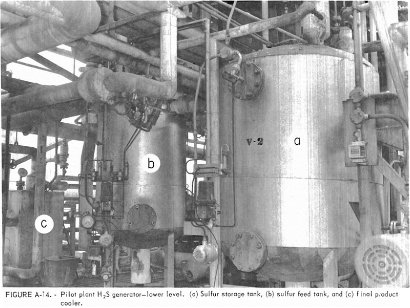
Molten sulfur produced in the pilot plant was transferred to a sulfur feed tank from which it was pumped through a filter to remove carbon and ash impurities and to a gas-fired superheater. The sulfur was vaporized and superheated to about 1,350° F. Natural gas containing about 92 pct methane at 1,200° F from a second superheater was combined with the hot sulfur vapor ahead of reactor 1. The sulfur-methane reaction produces H2S and CS2 over a catalyst in this reactor according to reaction 4.
The H2S-CS2 product gas was first air-cooled to about 800° F and then further cooled in a steam-cooled heat exchanger to about 300° F. Excess sulfur was condensed in the reactor product cooler and was removed from the gas mixture in the first sulfur knockout tank.
Steam at 800° F from a third superheater was combined with the cooled H2S-CS2 gas prior to entering reactor 2. In this reactor, the CS2 was hydrolyzed to H2S and CO2 in a catalyst bed at 700° F according to reaction 5.
A side reaction occurs during CS2 hydrolysis to form COS according to reaction 6. In the laboratory it was determined that reaction 6 was depressed by feeding excess steam and favored by high reaction temperatures.
A steam-cooled heat exchanger cooled the reactor 2 product gas to 300° F to condense free sulfur. The condensed sulfur was removed in two additional knockout tanks. Sulfur collected in all three knockout tanks was periodically drained to the sulfur feed tank. Product gas from the second reactor, containing H2S, CO2 , and some water vapor, was cooled to about 149° F in a water-cooled heat exchanger and then fed to the solution regeneration section of the citrate pilot plant.
The major problem experienced during the pretesting of the H2S generator was the inability to heat reactor 1 to the desired temperature. Thus, the sulfur vaporizer piping was damaged when attempting to provide the necessary heat for the reaction. This was solved by shortening the process piping between the superheaters and reactor 1, adding insulation to process piping and reactor 1, and feeding excess sulfur to carry more heat to reactor 1.
After pretesting, the operation of the H2S generator was integrated with the operation of the SO2 absorption, solution regeneration, and sulfur recovery section. Two operating problems developed during continuous operation. The first, and probably the most chronic, was plugging of the cold H2S product lines and valves with sulfur. This was partially solved by modifying the final sulfur knockout tank to cool the product gas with a water jacket. This mode of operation required periodic steam heating to clear the knockout tank of sulfur. The second problem, plugging of the sulfur superheater coil with metal sulfides, was due to high temperature corrosion.
Reactor 2 was bypassed as indicated in figure 4 after achieving reliable operation with two stages. This allowed reaction 7 to take place in reactor 1. The operation proceeded without any additional problems; the only noticeable difference was that the product H2S contained more COS and CH4.
Next, both the steam and natural gas superheaters were eliminated. All reactant feed materials were superheated in the sulfur superheater. Again the plant worked satisfactorily; the only noticeable difference was that the temperature of the superheater could be reduced about 100° F without affecting the H2S product quality. This difference is probably due to an increase in the overall reaction time. The advantages of single-stage operation would be the elimination of capital equipment and possibly reduced corrosion in high-temperature equipment.
Between April 1975 and May 1976, the H2S generator operated for about 3,090 hr and provided the H2S required for SO2 reduction in the citrate process. During the latter 2,369 hr of this time, the one-stage operation was used.
Table 8 summarizes results of the H2S generator operation under reasonably steady-state continuous operation. During this time sulfur was fed to the H2S generator while varying the natural gas and steam flows to change the H2S production rate. Throughout most of the H2S generator operation, the sulfur flow was about 160 lb/hr. This flow provided between 150 and 300 pct excess sulfur, which was recovered and recycled. The large amount of excess sulfur was used to prevent overheating of the sulfur vaporizer coil and to transfer heat to the first reactor. During the two-stage operation, a 25-pct excess of steam was used to prevent COS formation. During the one-stage operation, where the CS2 hydrolysis occurs at a higher temperature, a 50-pct excess of steam was necessary to achieve low COS in the product gas. The first reactor inlet and outlet skin temperatures both averaged about 1,050° F While operating with two stages, the second reactor inlet and outlet temperatures averaged 430° F and 655° F, respectively. In addition to the principal gas analyses listed in table 8, the H2S product gas contained about 1 pct N2 and traces of CS2, CO, and O2.
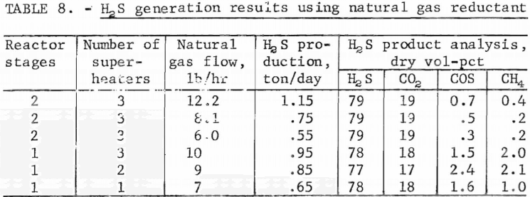
The test results show that the two-stage operation of the pilot plant makes the most efficient use of natural gas and produces the least amount of undesirable COS. The decrease in CH4 utilization during one-stage operation, as indicated by the higher CH4 in the product gas, may be caused by the increased space velocity through the first reactor. The COS in the H2S product gas was vented from the sulfur precipitation reactors and incinerated to SO2 and CO2. By all methods of operation, the H2S generator produced a gas that analyzed between 77 and 79 pct H2S and was suitable for the SO2 reduction.
The quantities of sulfur, CH4 , and steam required for the H2S generator for each short ton of H2S produced were
- Sulfur, 1,900 lb.
- CH4, 5,600 std cu ft.
- Steam, 1,000 lb.
These quantities include 1 pct COS, 0.5 pct CH4, and 50 pct excess steam in the H2S product.
Sulfur dioxide reduction was tried with a gas of lower H2S content. This gas could be produced with a CO-H2 mixture from a coal gasifier. This would eliminate the need for natural gas reductant in the citrate process. The H2S reactor 1 was operated at 900° F which reduced the reaction rate. This produced a gas that contained on a dry volume-percent basis, 56 H2S, 15 CO2 , 24 CH4 , 1 COS, 0.5 CS2 , 2 N2 , and trace CO and O2, that was suitable for SO2 reduction.
Under a cooperative agreement, Morrison-Knudsen Co., Inc., briefly tested other gaseous reductant feeds to replace natural gas for H2S generation.
Table 9 summarizes results of the H2S generator operation using propane, methanol, and carbon monoxide as reductant feeds. The tests used the one-stage operation in which the sulfur superheater vaporized and heated the sulfur, reductant, and steam. The test conditions were similar to those used in producing H2S from sulfur, natural gas, and steam.
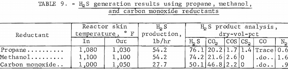
The test results showed that all processes resulted in the production of an H2S gas that could be used in the citrate process. The lower temperatures needed for H2S production from sulfur, carbon monoxide, and steam may reduce the energy requirement and the corrosion in the sulfur superheater coil and
high-temperature process piping.
In general, the H2S generator worked reasonably well after initial shakedown problems were eliminated. With additional refinements it should be able to produce suitable H2S at a rate to match the normal requirements of the citrate process. However, corrosion and plugging of lines may be a continuing maintenance problem, even though probably reduced in a larger scale operation.
Safety
Safety was an overriding consideration in design, construction, and operation of the pilot plant. Trace quantities of hydrogen sulfide may not be harmful and are easily detected by the characteristic foul odor. However, high concentrations destroy the ability to detect the odor and concentrations of only 0.1 pct H2S are lethal. For this reason, the pilot plant emergency ventilation system was designed and installed for a complete air change in the building every 2 minutes. The emergency ventilation fan took suction from a ducted hood in the immediate vicinity of the reactors where H2S leaks were most likely to occur.
The pilot plant was equipped with an H2S detector alarm system that consisted of remote H2S detection sensors, one in the solution regeneration reactor area, two in the H2S storage tank areas, three in the H2S generator area, and one in the control room adjacent to the central H2S alarm system control panel. An audible bell system was set to alarm at an H2S concentration of 10 ppm followed by a wailing horn that sounded if a concentration of 25 ppm was reached. The emergency ventilation fans were set to start and an automatic valve was set to close if the 25-ppm level was reached in the process area. During actual pilot-plant operation, the H2S concentration rarely reached a level that set off the alarms. However, smaller concentrations in the range of 0 to 4 ppm were frequently encountered. These concentrations were rarely high enough to show on the H2S sensors; nevertheless, they were objectionable. A program was instituted for regularly checking H2S concentration in the plant by visual inspection of H2S indicating cards that are sensitive to a fraction of 1 ppm H2S. These cards enabled us to detect very small leaks and repair them before the alarm system ever became activated. A commercial syringe-type detector, which involves drawing an air sample through a sensitized material in a glass tube and observing the length of stain produced, was also used for pinpointing H2S and SO2 leaks. This monitoring was not as sensitive as the indicator cards and was more time-consuming. A simple substitute for the cards consisted of small strips of filter paper saturated with lead acetate solution that were also sensitive to a fraction of 1 ppm H2S.
Several types of air breathing masks were available for working where a serious leak could occur. For small jobs such as disconnecting lines containing residual H2S, a 30-min backpack unit having a full face mask was used. A 7-min, self-contained, over-the-shoulder-type escape breathing mask was carried at all times for routine inspection of the H2S storage and vaporization area or the H2S generator. It was not worn unless there was a known or suspected leak of H2S. This type of mask could also be used for a longer period of time by attaching the mask to the hose on a larger compressed breathing air container. A refill station was provided so that when empty, the air containers could be recharged with breathing air.
The control room and laboratory section of the pilot plant, which was a modified 40-ft trailer, had a separate ventilating system. It consisted of a fan, a heater, and a carbon-filled air purification filter on the fan suction. The carbon filter removed SO2 and smelter dusts from the air.
Provisions must be made for disposing of H2S during upset periods in plant operations. Also, a small continuous stream of carbon dioxide containing 5 to 15 vol-pct H2S was discharged from the reactor vent when using 78 vol-pct H2S for regenerating the absorbent solution. This gas was vented through a fan acting as a flame arrester to a natural gas-fired incinerator. The H2S was burned to SO2 before being discharged to the stack. In a larger plant striving for zero air-pollution, it would be necessary to feed the offgas from the incinerator back into the gas cleaning system. The incinerator was supplied with two burners as a safety factor. Only one was required during routine operation; however, both were used to bring the incinerator up to operating temperature. The entire H2S generator product could be burned in the incinerator. This permitted operation of the H2S generator when the SO2, absorption section was down.
Personnel Requirements
Four persons per shift were required for the pilot-plant operation, maintenance, and testing. One operated the SO2 absorption, solution regeneration, and sulfur recovery section and one operated the H2S generator. A shift foreman was responsible for both sections and helped operators when needed. On day shift, an operator was needed to run the sulfur melting section. A plant supervisor was present on day shift. Instrument repair and general troubleshooting was done by the contractor’s representative, but most routine maintenance was done by plant operators. At times it was necessary to schedule a person for swing shift to finish sulfur melting and help with plant maintenance.
Corrosion Testing
Except for corrosion already mentioned and some problems with FRP joint leaks, all materials of construction used for the gas cooling and cleaning and the SO2 absorption, solution regeneration, and sulfur recovery section were satisfactory. To evaluate other stainless steels and alloys, corrosion test specimens were placed in various locations in the Bunker Hill pilot plant prior to the start of operation in January 1974, and were examined after the plant was shutdown in May 1976. Appendix G shows the location of test specimens in the process. Appendix G also shows the corrosion in mils per year for the various metals in the locations specified. For equipment handling citrate or glycolate solution, it appears that type 304 stainless steel would be the most economical choice of metals, even in the sulfur melting equipment. Materials to avoid in the sulfur melting equipment appear to be the Hastelloy G, Hastelloy C-276, and type 316 stainless steels. Although none of the metals was severely attacked, the most corrosive service was the humidifier-scrubber where both the type 304 and type 316 stainless steels showed pitting. The best resistance to corrosion in this area was shown by the Hastelloy G, Hastelloy C-276, Inconel 617, Inconel 625, Inconel 617 sensitized, and type 317 stainless steels. As stated before, ‘FRP and PVC plastics were satisfactory where temperature and mechanical strength requirements permitted. It should be mentioned that the presence of fluorides , chlorides, or other ions not found in the pilot-plant solutions might result in different requirements for other installations.
Summary and Conclusions
Prolonged pilot-plant testing has shown the Bureau of Mines citrate process is capable of substantially complete removal of SO2 from the lead smelter sintering furnace tail gases.
Operational problems during pilot-plant testing of greatest concern are as follows:
- Plugging of the sulfur slurry overflow pipelines between reactors with sulfur, which required periodic cleanout,
- Plugging of the H2S generator product pipeline with sulfur, which required periodic cleanout.
- Corrosion of the sulfur vaporizer coil and high-temperature pipeline in the H2S generator.
The plugging of pipelines with sulfur may be solved in larger scale plants. The corrosion of the sulfur vaporizer coil and high-temperature pipelines may be reduced in larger scale plants, but will continue to be a maintenance problem.
The operation demonstrated that
- Ninety-nine percent of the SO2 could be removed from lead smelter sintering machine waste gases containing from 0.1 to 0.6 vol-pct SO2.
- Regeneration of the solution with H2S and precipitation of sulfur in conventional stirred vessels was readily controlled.
- Precipitated sulfur could be continuously recovered as a 99.5-pct- pure product by kerosine or air flotation and melting.
- Only 1.5 pct of the SO2 was converted to sulfate, regardless of the SO2 and oxygen content of the feed gas.
- Seventy-eight dry volume-percent H2S could be readily produced from pilot-plant sulfur, natural gas, and steam.
- A 56-dry-vol-pct H2S gas, that might be produced using a synthesis gas (CO-H2) derived from coal, could be used for solution regeneration.
- H2S gas may be produced using the reductants methanol, propane, or carbon monoxide.
8. Materials of construction for S02 absorption, solution regeneration, and sulfur recovery equipment were satisfactory.
The ability of the process to capture over 95 pct of the SO2 with conversion to storable sulfur of potential economic value justifies continued study and development.
A goal of the Federal Bureau of Mines is to minimize the undersirable environmental conflicts and impacts associated with mineral processing operations. To help reach this goal the Bureau operated a citrate-process pilot plant for the removal of sulfur dioxide from lead smelter sintering machine waste gases to test the process. The process uses a carboxylate solution such as citric acid to absorb sulfur dioxide from waste gases. The absorbed sulfur dioxide is subsequently reacted with hydrogen sulfide to precipitate sulfur and regenerate the solution for recycle. Nominal capacity of the pilot plant was 1,000 scfm of 0.5 vol-pct sulfur dioxide gas. The pilot plant was operated for over 5,400 hr and produced about 55 net tons of sulfur. The operation demonstrated that (1) 99 pct of the sulfur dioxide could be removed from lead smelter sintering machining waste gases containing from 0.1 to 0.6 vol-pct sulfur dioxide, (2) sulfur precipitation and solution regeneration with hydrogen sulfide in conventional stirred vessels was readily controlled, (3) precipitated sulfur could be continuously recovered as a 99.5-pct-pure product by flotation and melting, and (4) 78 dry-vol-pct hydrogen sulfide gas could be produced from pilot-plant product sulfur, natural gas, and steam.
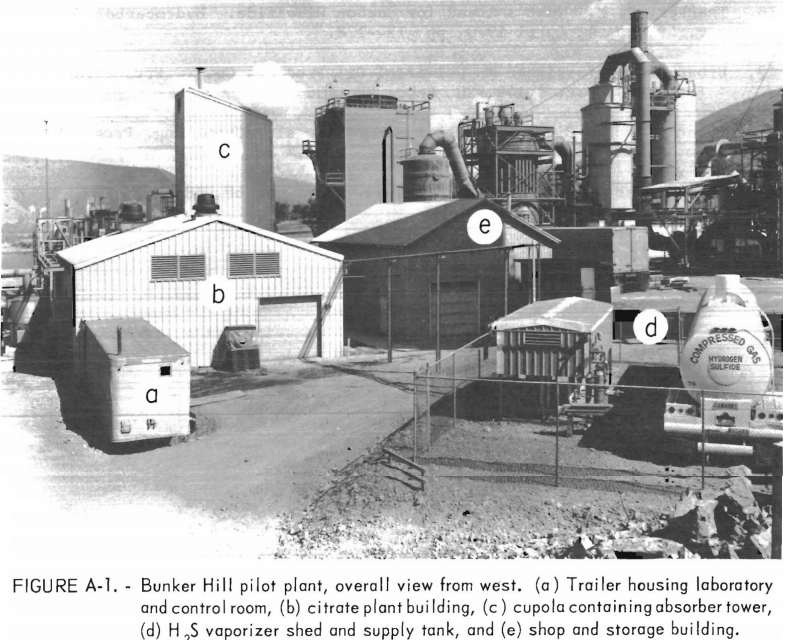
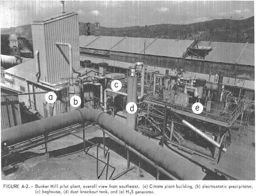
Appendix A. — Bunker Hill Pilot-Plant Process Equipment
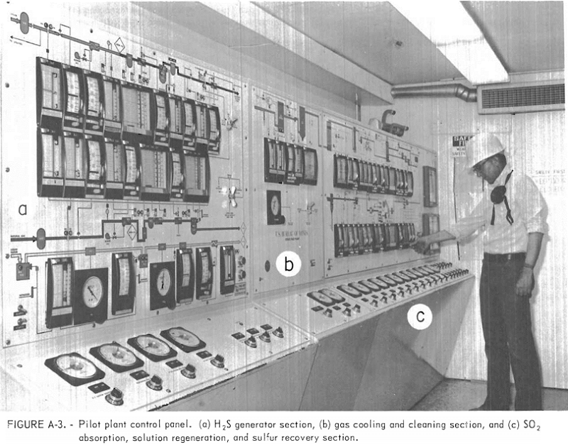
Essential items of equipment contained in the citrate-process pilot plant are shown in the photographs of Appendix A.
Appendix B—Bunker Hill Pilot-Plant Equipment List
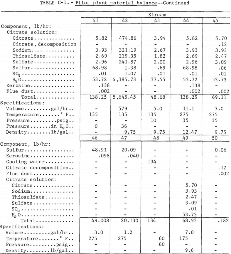
Appendix C—Bunker Hill Pilot-Plant Material Balance
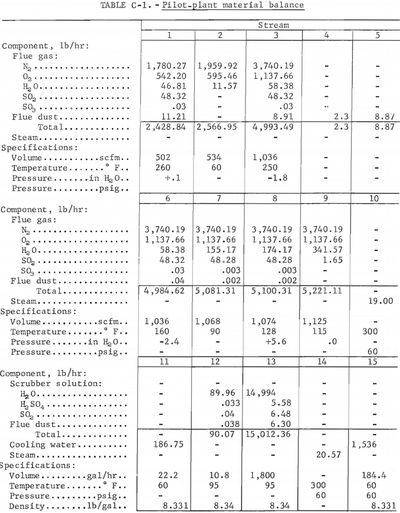
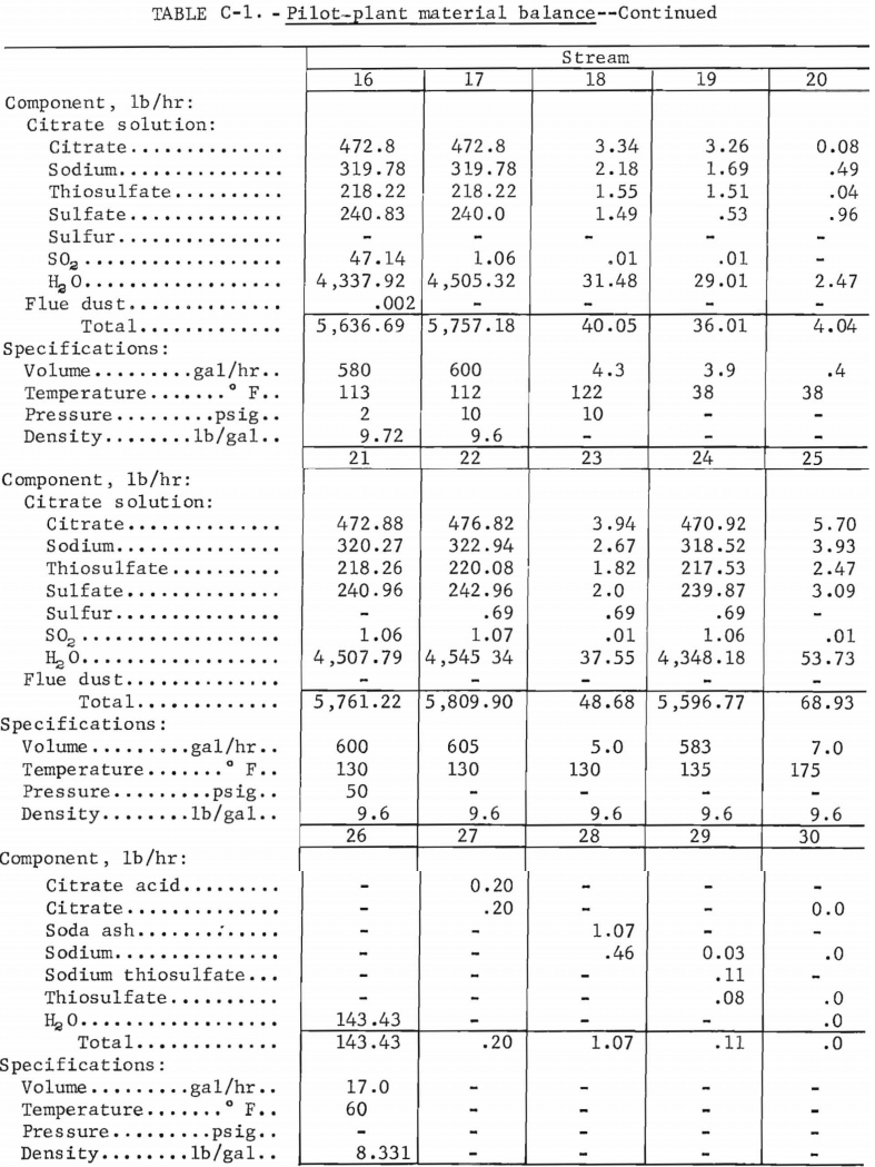
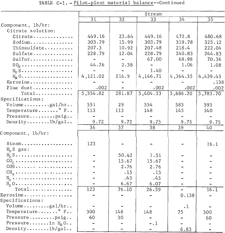
Figures C-1—C-5 present the detailed process flow diagrams of the Bunker Hill pilot plant. These diagrams show the stream numbers for the material balance that is presented in table C-1. The material balance calculations are based on the best available estimate of average performance at the Bunker Hill pilot plant rather than using any one specific time period. The conditions specified include gas flow to the absorber of 1,074 scfm (32° F and 1 atm) of 0.420 pct SO2 feed gas containing 3.42 pct water. For this material balance, 96.5 pct SO2 absorption efficiency was used, which is the average for all pilot-plant tests. The absorbent solution used was 0.5 M citric acid, 0.5 M Na2CO3 and 0.39 M Na2S2O3 , and the flow to the absorber was 10 gal/min. The regenerated solution contained 0.22 g SO2 per liter and the rich solution contained 9.55 g SO2 per liter. The chemical requirements were, in pounds per net ton sulfur produced, 20 citric acid, 107 soda ash, and 11 sodium thiosulfate. The soda ash consumption is based on a 1.5-pct oxidation rate of SO2 to sulfate in the system. Fourteen percent of this sulfate formation is assumed to occur in the autoclave due to thiosulfate decomposition and the thiosulfate makeup is calculated from this value. The remaining oxidation for simplicity is assumed to take place in the absorption tower. Water addition at the makeup tank is needed to complete the water balance for the temperatures shown on the flow sheet. The decomposition loss of citrate is assumed to take place at the sulfur melter recycle solution trap for convenience since the mechanism of citrate loss is unknown. This loss plus that lost in the sulfate removal step totals the overall citrate loss of 20 lb per net ton of sulfur.
Kerosine loss is shown leaving with the sulfur product and recycle sulfur for H2S generation. This kerosine consumption was found to be adequate toward the end of the pilot-plant run after the addition point was changed to a point in the conditioner just above the overflow. The amount of dust and SO3 was measured by an Anderson stack gas sampler using the U.S. Environmental Protection Agency (EPA) method 5 for particulates , and a sample train similar to EPA method 8 for SO3. The dust escaping the gas cleaning equipment measured at 0.013 mg/cu ft. Ninety five percent of the dust was assumed to be picked up in the product sulfur as impurities. This value checks fairly close with average impurities recovered from the sulfur melter recycle solution trap or kerosine decanter. The values used in the material balance closely match the conditions for the period December 2 to December 12, 1974, as far as temperatures and liquid and gas SO2 loadings are concerned. Other periods that closely match the conditions, except for the temperature, are the periods of July 18 to August 17, 1975, and August 24 to September 3, 1975.
Several simplifying assumptions were made relating to flotation efficiency. These assumptions are that (1) 2 pct of the sulfur escapes the flotation system, (2) 1 pct of the sulfur being settled and returned to the conditioner by a pump, and (3) 1 pct of the sulfur escaping the settler to the absorber feed tank where the sulfur is recovered by the clarification filters and also returned to the conditioner. Also, 40 gal per shift of flush solution is assumed for both flotation system recycle streams since there was no actual measurement made.
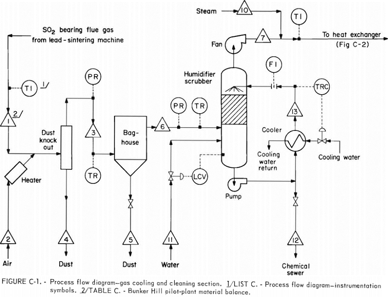
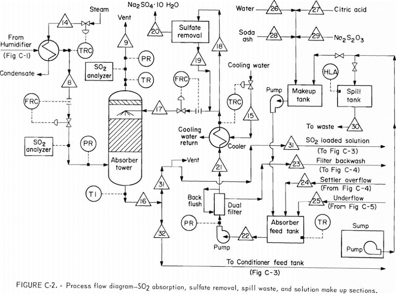
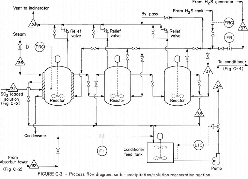
List C-1. – Process Flow Diagram Instrumentation Symbols
TI—Temperature indicator,
TR—Temperature recorder.
TRC—Temperature recorder-controller.
PR—Pressure recorder.
PRC—Pressure recorder-controller.
LIC—Level indicator-controller.
LCV—Level control valve.
LRC—Level recorder-controller.
FI—Flow indicator.
FR—Flow recorder.
FRC—Flow recorder controller.