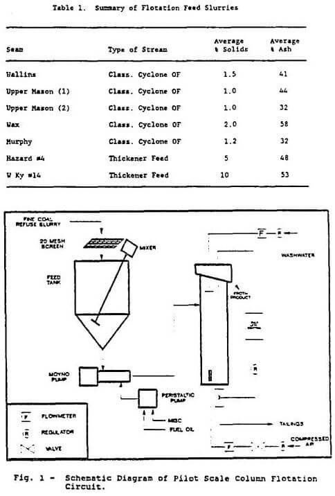
Flotation feed was obtained at the various preparation plants by diverting slurry from either the thickener feed, classifying cyclone overflow or fine refuse sump depending on the plant circuit. In each case, the slurry was obtained from a waste stream prior to any flocculant addition and stored in a 650 liter (170 gallon) agitated mix tank. The slurry was then pumped into the flotation column (0.15m or 6 inch ID x 5.79m or 19 ft. high) by a variable speed pump. Appropriate reagents were added on the inlet side of the pump. The feed inlet to the column was located 2.44m (8 ft.) below the froth overflow; washwater was added through a simple shower head while air bubbles were produced by forcing air through a stainless steel sparger. Flotation tailings were discharged by gravity and the discharge flow was controlled by an automatic air controlled valve interfaced with a pulp level sensor. A schematic diagram of the testing layout is shown in Figure 1.
All sample collection was conducted by simultaneously collecting samples of the clean coal froth, tailings and flotation feed after the column operated at steady-state conditions for a minimum of 20 minutes. This provided more than three times the retention time of slurry in the column. When any charges were made in operating conditions samples were again collected only after 20 minutes of operation at steady-state conditions.
The flotation characteristics in terms of combustible recovery and concentrate grade were established using a Denver Model D12 batch flotation machine and varying amounts of fuel oil and frother. Optimum fuel oil dosage for most seams was 0.25-0.5 lb/ton (0.12-0.25 kg/mt); the exception was the W. Ky 14 seam which required a fuel oil dosage of 1.5 lb/ton (0.75 kg/mt). The frother concentration required for all seams was 0.12 kg/mt (0.25 lb/ton) despite the wide range of feed solids investigated.
Pilot scale column flotation tests were conducted with a 0.15m (6 inch) I.D. column to recover a clean coal product from refuse streams produced by several preparation plants. A total of 7 seams were investigated varying from 1.0 to 15.0% solids containing 32-64% ash.
Increasing washwater addition rate was shown to improve concentrate grade for all of the seams tested with no effect on recovery while some of the seams showed reduced recovery with higher washwater addition rates presumably due to froth breakage.
Good combustible recovery (80-90%) was obtained with each seam tested when sufficient retention time was provided. The minimum retention time required to achieve this recovery increased as the feed solids, also increased. This could be partially due to the different hydropholic properties of each seam but may also be attributed to the need for additional bubble surface area when a larger amount of hydrophobic particles are present. Increasing the airflow rate to produce more bubbles increased recovery when higher feed solids slurries were processed. When the feed solids was constant, recovery was diminished as the airflow rate was reduced with no significant effect on concentrate grade.
|
|
 |
Pilot Plant Description
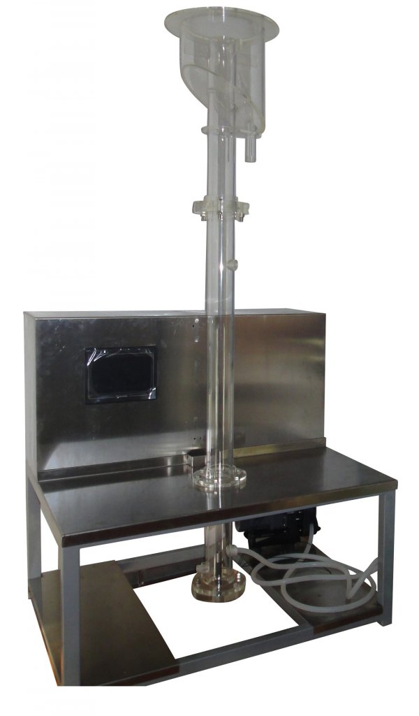
The pilot plant consists of three clear acrylic flotation columns 16 cm diameter by 5.5 m high as well as a four cell bank of Denver 7 mechanical cells. The bank of mechanical cells has approximately the same volume as one of the columns. Solids processing rate of the pilot plant is 1.5 to 4 t/d, depending on the feed stream. Fabric and rubber are both used for gas sparging. Slurry is pumped using high capacity peristaltic pumps, with manual control of pump speed on feed pumps and remote control of pump speed on column tailings pumps. In total, the pilot plant has thirteen slurry pumps and seven sumps and mixers. The plant is a self sufficient and self supporting structure occupying a floor space of 3m by 3m and a height of 6.5m when assembled.
The pilot plant is controlled by the Minnovex column control system, ColumnEX. This system uses zone density measurements for level control and has full expert system capabilities to incorporate other control strategies such as wash water and air control from zone densities and alarm diagnostics.
Pressure measurements are made with 0-6 and 0-15 psi flush mount pressure transducers requiring a 5 V supply and having a linear 0-100 mv output. The transducers are located on the columns such that one transducer (measuring gauge pressure P1 at distance H1 from the top of the column) is in the froth zone and the other two are within the collection zone: one near the top of the collection zone (measuring pressure P2 at distance H2 from the top of the column) and one near the bottom (measuring pressure P3 at distance H3 from the top of the column). These three measurements provide the following information on each column:
- froth zone density
- collection zone density
- interface (or froth) depth Hf.
Hf is calculated from (Dirsus, 1988)
Hf = P2 – H2((P3-P2)/(H3-H2))/P1/H1 – (P3-P2)/(H3-H2)
(Pressure values are in units of water head.) The system allows for an offset factor for measured level, such that the measured level is usually within 5 to 10 cm of the true level.
Built-in PI control software for each column is used to maintain froth depth set point (by regulating tailings flow).
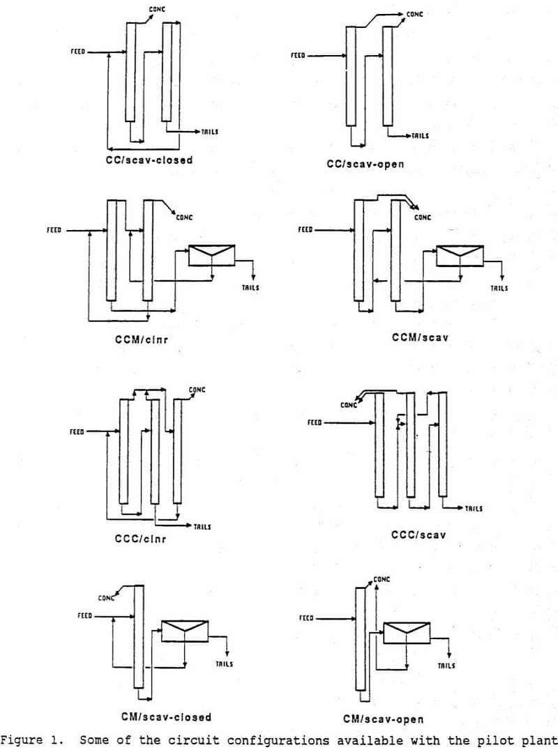
Some of the circuit configurations available with the pilot plant are summarized in Figure 1. The coding of circuit arrangements is noted in this Figure. For an example of the coding, CCM/cleaner refers to the circuit consisting of two columns plus the bank of mechanical cells, with tailings from the first column feeding the mechanical cells, combined concentrate from the first column and the mechanical cells feeding the second column (2nd cleaner) and second column tailings recycled to first column feed.
Pilot Plant Operation
The program began with testing on zinc final concentrate and then shifted to zinc rougher concentrate, copper rougher concentrate, and finally zinc rougher feed. The data reported here is from work on the zinc and copper rougher concentrates. The zinc rougher concentrate was typically 40 to 45% Zn, with pyrite as the principal contaminant. The existing mechanical cell zinc cleaning circuit consists of three stages of open circuit cleaning. Copper rougher concentrate varied from 10% to 20% Cu, with sphalerite, pyrite and silicates as contaminants. Existing copper cleaning is performed by three stages of conventional counter-current cleaning. Feed flowrate to the pilot plant was 3 to 6 L/min of slurry.
- Flotation columns are suitable for applications such as zinc or copper cleaner scavenging. In these applications wash water is not generally required.
- Flotation columns can operate well without wash water addition in the first cleaning stages of a recleaner circuit.
- A three-column cleaning circuit will give at least equivalent performance (and probably slightly better) than a circuit with two columns and one bank of mechanical cells (of similar capacity to one column).