Table of Contents
This method may be economical for certain low-grade deposits by minimizing the transport of material to the surface for the recovery of valuable mineral. Application of the in situ stope leaching technique is site specific and would require detailed site characterization studies for preparation of an environmental impact statement and permitting for its design, construction, and operation. In situ stope leaching consists of fragmenting ore, introducing chemicals to extract metal, and collecting and processing the metal-bearing solution
Bulkhead Design Methodology
Several factors should be considered prior to the design of a bulkhead. The following section describes the methodology and equations used. The factors considered for design and construction of a reinforced concrete bulkhead include bulkhead pressure gradient, shear strength, reinforced concrete flexure, reinforced concrete beam bending stress, critical section bulkhead shear strength, shrinkage and temperature reinforcement, and low-pressure grout thickness.
The pressure gradient across a bulkhead, Pg, is the ratio of the hydrostatic pressure, P, measured in psi and the bulkhead thickness, t, in ft. The pressure gradient for a bulkhead is calculated as follows:
where Pg = pressure gradient, psi/ft,
P = hydrostatic pressure, psi,
γw = solution density, lb/cf,
h1 = stope height (distance between roof of lower drift and floor of upper drift), ft,
h2 = drift height (distance between floor and roof of lower drift), ft,
and t = bulkhead thickness (distance between exterior and interior reinforced concrete wall), ft.
f’s = 2√f’c……………………………………………………………………………………(3)
where f’s = concrete shear strength, psi,
and fc’ = concrete compressive strength, psi.
For the 2,500 psi compressive strength concrete used for designing the stope leach bulkhead, the calculated shear strength allowed is 100 psi. Assuming that shear would occur just inside the concrete/rock interface, the bulkhead thickness can be determined using this equation:
t = Pab/2(a+b)fs’…………………………………………………………………….(4)
where t = bulkhead thickness for a specific rock shear strength, ft,
a = drift width (distance between drift walls), ft.
b = drift height, ft,
P = hydrostatic pressure (eq. 2), psi.
and fs’ = lesser of shear stress for rock or concrete, psi.
Reinforced Concrete Flexure
The ratio is calculated as follows:
Pmin = 200/fy…………………………………………………………(5)
where Pmin = proportion of steel area to yield strength,
and fy = yield strength for steel, psi.
The ratio of “nonprestressed tension reinforcement” can be calculated using the following equation:
Pw = As/bwd…………………………………………………………………(6)
where pw = steel area to effective beam area ratio,
bw = web width, ft,
and d = extreme compression fiber distance from bar centroid, ft.
As = area of reinforcing steel in the beam, in².
Reinforced Concrete Beam Bending Stress
In situ stope bulkhead design to support the bending moment developed in the reinforced concrete bulkhead follows the reinforced concrete code criteria developed by ACI (ACI 318 R92, Sec 9.3.2.1, Sec 10.5.1, Sec 11.8; Wang and Salmon, 1985; Einarson and Abel, 1990). The flexure strength of the equivalent rectangular compressive stressed concrete block according to Whitney (Wang and Salmon, 1985) can be estimated as follows:
C = Φ fc’bwa……………………………………………………………….(7)
T = As fy……………………………………………………………………..(8)
where C = compressive force in concrete, lb,
Φ = concrete strength reduction factor (0.85),
fc’ = concrete compressive strength, psi (2,500 psi),
bw = width of compression face of member, in,
a = depth of equivalent rectangular stress block, in,
T = tensile force in steel, lb,
As = area of tension steel, in²,
and fy = specified yield strength of nonprestressed steel reinforcement, psi (60,000 psi).
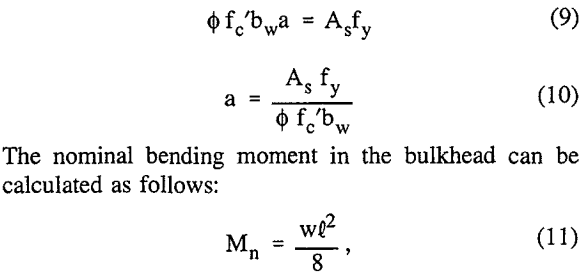
where Mn = nominal beam moment, ft.-lb,
l = drift width, (note notation for drift width in equation 4 is presented as a”), ft,
and w = bulkhead load, lb/ft.
The factored bending moment in flexure is defined as
Mu = Mn/Φ……………………………………………………………….(12)
where Mu = factored beam bending moment, ft-lb,
and Φ = steel strength reduction factor (0.90).
The beam bending moment about the center of the compressive stress area is
Mu = T(d-a/2)…………………………………………………………..(13)
Critical Section Bulkhead Shear Strength
The factored shear load, Vu, and bending moment, Mu, for a 1-ft-wide beam at the critical section at a distance, d, from the face of support (drift-rib side) for a simply supported, uniformly loaded, one-way beam, are calculated as follows:
w = u = ΦPg (144)…………………………………………………………………………….(14)
where w = uniform load, lb/ft,
u = required strength, lb/ft,
Φ = strength reduction factor (1.4),
P = pressure gradient (from equation 1), psi/ft.
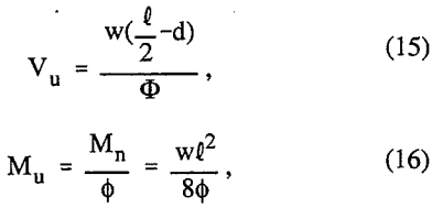
where Vu = factored shear force, lb,
t = drift width (note notation for drift width in equation 4 is presented as,”a”), ft,
d = distance, extreme compression fiber to rebar centroid, in,
Φ = strength reduction factor for concrete shear (0.85) and for steel in tension (0.90),
Mu = factored bending moment, ft-lb,
Mn = nominal beam moment, ft-lb,
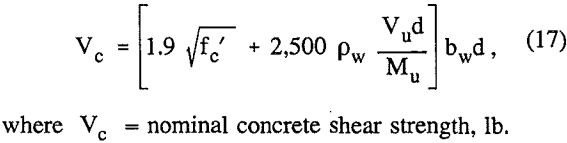
For a safe design, the ratio of Vud to Mu should not be greater than one. The nominal shear strength, Vc, of a nonprestressed bulkhead subject to shear and flexure only, provided by concrete, tension reinforcing and shrinkage, and temperature steel (ACI 318R, Sec. 11.1, Sec. 11.3.2.1) is calculated as follows:
When shear reinforcement perpendicular to the axis of the member is used, the following steel shear strength, V, equation applies:
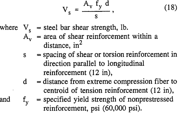
For safe design, the steel shear strength is limited to
Vs ≤ 8√f’c bw d………………………………………………………………(19)
where fc’ = specified compressive strength of concrete (2,500 psi),
bw = web width (12 in),
and d = distance from extreme compression fiber to centroid of tension reinforcement (12 in).
Shrinkage and Temperature Reinforcement
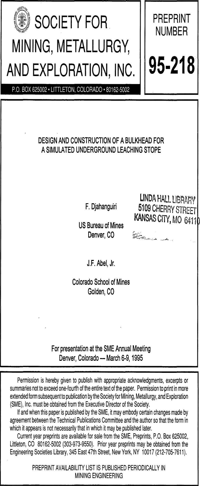
Non load-bearing shrinkage and temperature reinforcement of No. 6 bars on 12-in centers at upstream face to gross concrete area, p, of upstream half of bulkhead slab must equal or exceed 0.0018 [ACI318R-92, Sec 7.12.2.1 (b)] for Grade 60 deformed bars. No. 6 bars on 12-in centers provide a steel area of 0.44 in²/ft.
No. 6 bars provide adequate shrinkage and reinforcement.
Low-Pressure Grout Bulkhead Thickness
The maximum allowable bulkhead pressure is calculated as follows:
PB = γw/144(h1 + h2)……………………………………………………………………………..(21)
where PB = maximum bulkhead pressure, (note eq. 21 is identical to eq. 2), psi,
h1, = stope height, ft,
h2 = drift height, ft,
and γw = water density, 62.4lb/ft³.
The required bulkhead thickness, tr is given by the following equation:
tr = PB/PL………………………………………………………………….(22)
where PL = allowable hydraulic gradient, psi. The length of the concrete bulkhead was increased to 14 in (1.17 ft (0.36 m)) for ease of anchoring the reinforcing bars into the drift walls.
Bulkhead Construction and Concrete Placement Procedure
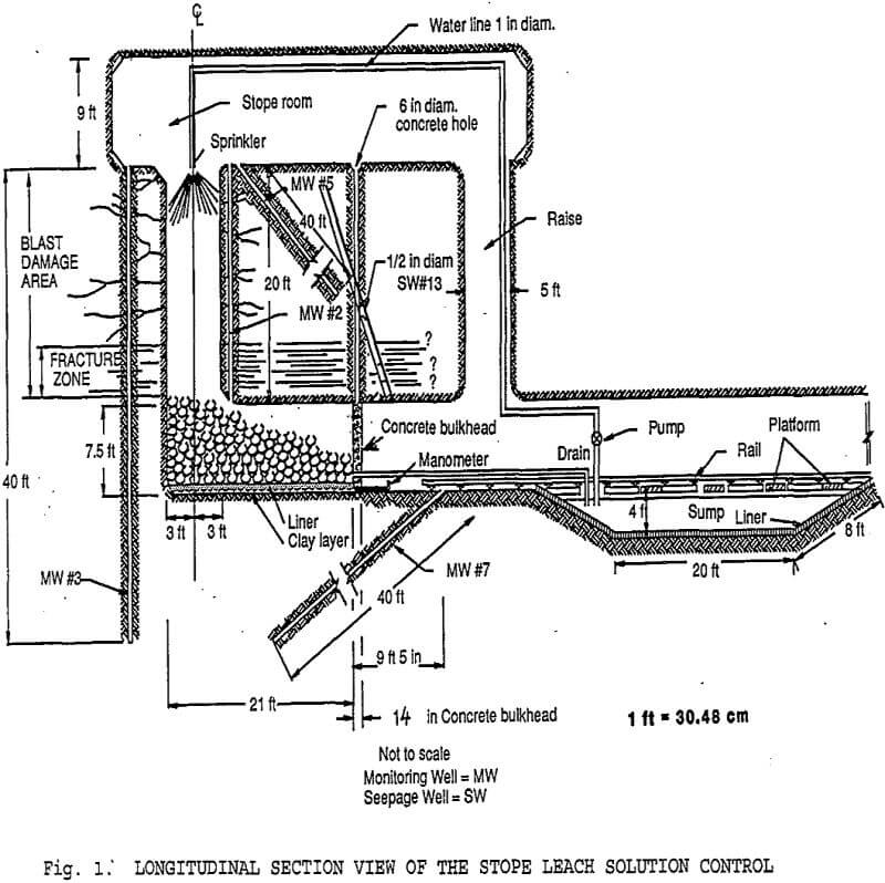
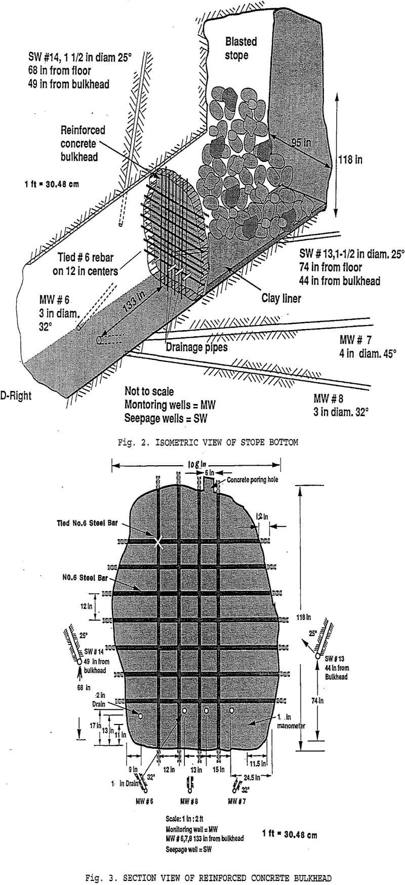
SULS served to impound and control the in situ stope leach solution during flooding and hydrologic site studies. A 14-in (0.36-m) reinforced concrete bulkhead was designed and constructed in the D-right drift approximately 12 ft (3.7 m) from the drift face at an overburden depth of 590 ft (180 m). Initially, the contact between the bulkhead and the wall/rock was not grouted. The bulkhead was tested by partial flooding of the stope site, and leakage developed at a rate of approximately 10 gpm (38 Lpm). The test site was subsequently drained.
Bulkhead Depth Based on Hydraulic Pressure
Formation breakdown pressure (Bp) is estimated by the following equation (Bredehoeft, et al, 1976; Einarson and Abel, 1990):
Bp = Ts + 3Smin – Smax – Pf………………………………………………………….(23)
where Ts = tensile strength, psi
Smin = minimum stress normal to borehole, psi
Smax = maximum stress normal to borehole, psi
and Pf = formation pore pressure, psi
The equation can be simplified by making the assumption of hydrostatic in situ stress (Smax = Smin) and that the formation is dry or drained (Pf = 0), such as is present at the leach stope bulkhead site.
Bp = 2σv…………………………………………………………………………….(24)
where Bp = breakdown pressure, psi,
σv = overburden stress, psi.
The overburden pressure is calculated as the density times depth of the overlying rock:
σv = γH/144 = 165(590)/144 = 676 psi (47 MPa)……………………………………………………(25)
where γ = overburden density, psf,
and H = overburden depth, ft.
Therefore, the calculated hydraulic pressure to produce hydrofracturing is
Bp = σv/2 = 676/2 = 338, psi (2.3 MPa)………………………………………………………….(26)
Corrosion Resistant Design
The corrosion rates and resulting probable life of piping of various stainless steels and pipe diameters were evaluated for approximate acid mine water concentrations and temperatures. The maximum surface corrosion rate reported by the manufacturer of Carpenter 20Cb-3 stainless steel pipe was less than 0.005 in/yr (0.127 mm/yr) for the maximum solution concentration, the maximum pressure, and the highest temperature (Einarson and Abel, 1990). One- and two-in-diam pipes were selected and analyzed for penetrating through the concrete bulkhead for the stope leaching project.