
Dikes for River Control.—Dredging and the maintenance of dredged depths is intimately related to the subject of the characteristics and regulation of rivers. This, however, is much too broad and far reaching in its scope to be included within the narrow confines of this small book, and will merely be summarized with maximum brevity in order to indicate its bearing upon our title subject.
The problem is the prevention of the silting-up and dislocation of dredged channels and areas by the agencies of sedimentation and scour. Since the surest cure is the removal of the cause, let us go back to the source and review hurriedly the marshalling of the forces of nature for the destruction of the works of man. The “rainfall,” i. e., both rain and melted snow, suffers one of three fates: Part of it is evaporated, part penetrates the earth surface to become “ground water,” which, pursuing subterranean courses, eventually reaches the river, and a third part remains upon the surface, constituting the surface drainage and creating the mountain torrent and, finally, through brook and creek, reaches the river. The “run-off” for a particular water-shed is the rainfall, less the evaporation, and thus comprises both surface drainage and ground water. The percent of run-off will be influenced by many factors, principal among which are the character of the soil, the slope, the vegetation, the climatic conditions and the degree of concentration of the precipitation throughout the year. The quantity of sediment and its rate of progress to the river depends upon the run-off and the factors upon which the run-off is dependent. The considerations thenceforth are the ability of the river to transport the sediment and to scour its banks and bed, and the study of the laws or characteristics governing such scour and deposit.
The sediment-bearing power of flowing water is a function of the velocity of flow. The velocity is a function of the slope of the river and its cross section. The velocity is not uniform, however, throughout the cross section. Near the banks and the bottom it is slower because of frictional resistance, and the maximum velocity will obtain somewhat above the mid point of the greatest depth. Sediment may be transported either in suspension or by being rolled along the bottom. The heavier the material, the greater is the velocity required. A velocity that is just sufficient to carry a particular class of material is unable to pick up that same material from a position of rest on the bottom. The deposition of sediment is caused by the checking of the velocity of the soil-bearing current due to obstruction or change in grade or cross section.
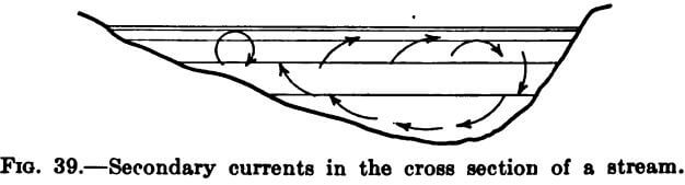
The principal water currents existing in a river are of two kinds; first, that in the direction of the river slope due to gravity; and, second, the transverse currents caused by change of direction of the river’s course. The velocity of the flow along the outer bank of a bend is naturally greater than on the inner, and, further, the axial current in resisting the change in direction, creates a radial, dynamic pressure acting toward the outer bank and setting up currents in that direction. By actual observation it has been found that these cross-currents move toward the outer bank near the river surface and toward the inner bank near the bottom or wetted perimeter of the cross section, somewhat as shown in the figure 39.
Thus it is the outer bank of a river on a bend that is subjected to scour and it is near the outer bank that the deepest water will be found; and the river, by simultaneously building up by deposit the inner bank of the bends, tends ever to an increasingly winding course. The fact that rivers of the least slope have the most bends is due in part to the greater relative influence of these cross-currents born of the radial pressure.
The weights of bodies that can be moved by the pressure of a current vary as the sixth power of the velocity, and the diameters of the bodies as the square of the velocity. Hence, an increase in velocity causes far greater increase in transporting capacity. Mansfield Merriman, in his Treatise on Hydraulics, gives the following table of approximate values:
Velocity of 0.25 feet per second moves fine clay.
Velocity of 0.5 feet per second moves loam and earth.
Velocity of 1.0 feet per second moves sand.
Velocity of 2.0 feet per second moves gravel.
Velocity of 3.0 feet per second moves pebbles 1″ in size.
Velocity of 4.0 feet per second moves spalls and stones.
Velocity of 6.0 feet per second moves large stones.
Rivers are opened to navigation either by the dredging of a deep water channel in their beds or by canalization. Minimum first cost and maintenance expense involve a coordination of the factors, minimum initial excavation and redredging. Often, the natural agencies of scour and sedimentation can be so regulated by artificial means as to reduce the cost of the maintenance of the dredged cuts by such an amount as to warrant the cost of those means. Such regulation takes the form of velocity control both in amount and direction by artificial changes in cross section and water course, involving the construction of training and spur dikes and bank protecting structures. To stabilize the course of the river and therefore the channel location, it may be necessary to prevent further undulation of course by protecting the outside bank of a bend against further recession. This may be accomplished by some sort of pavement upon the exposed slope such as vegetation, brush fascines, mattresses, sand bags, concrete bags, rip-rap or an apron of timber or concrete; or by a sheet pile revetment; or by a timber or concrete bulkhead. Or the bank may be retained by a series of dikes or jetties projecting out from the shore into the waterway. Such dikes are called spur dikes, and may be either solid or permeable, i.e., they may be an impervious current stop or they may have openings to permit the passage of the water at a reduced velocity. The current instead of attacking the bank, impinges upon the spur dikes and expends its energy in the creation of secondary currents and eddies until its velocity is so reduced in the area between dikes as to cause it to unload its suspended material. Again, it may be desired so to reduce the effective width of the river as to cause an increase of velocity sufficient to create scour where sedimentation had previously occurred and caused expensive redredging. Spur dikes act in this manner to a certain extent, but more often a training dike, which is nearly parallel to the water course, is employed. The training dike is generally of much greater length than the spur dike, and the resultant narrowing of the stream causes higher than original velocities for the same discharge. Sometimes an island is so situated in the stream that it becomes in effect a training dike upon the connection of its upper end with the main land.
Man-made dikes are of several principal types as follows:
- Earth Embankment, with or without protective paving.
- All-Stone Embankment, the submerged portion usually a rip-rap heap, deposited upon a brush mattress, and the superstructure either rip-rap of larger dimensions or coursed rubble.
- Composite Dike of rip-rap substructure surmounted by a gravity wall of masonry or concrete or by a timber crib.
- Single row of sheet piling, driven between wales attached to plumb, round piles and braced by batter piles. This type is well adapted to the permeable spur duke, as any desired percentage of permeability may be obtained by varying the width of aperture between successive sheet piles.
- Parallel rows of sheet piling, as above, enclosing a fill of suitable material and tied together through the fill with wire rope, chain or rods. Additional lateral stability may be provided by spur piles in both directions transversely in the fill.
- Timber Crib with good heavy filling.
In choosing a typical section, the designer should have in mind the forces to be resisted, i.e., the “loading” of the dike. Since we are treating only of such dikes as are built in the river and not of the “levee” which confines the river itself, the hydrostatic head due to differences of elevation upon the two sides will be negligible, and the only loads to be considered are the weight of the structure itself, current scour, wave action and ice. An analysis of wave action reveals five components:
- The normal impact due to the waves’ momentum.
- The upward force parallel to the face of the dike tending to sheer off protruding members.
- Hydrostatic head due to the increased elevation of the water surface.
- Internal pressures due to the imparting of impulses to the water and air contained within the interstices of the dike.
- The back suctions as the wave recedes.
Ice may create a very considerable thrust against the dike, limitied in intensity only by the ultimate crushing strength of the ice.
For training purposes, in localities where the quarries are available, the stone dike probably gives the most complete all-round satisfaction. A brush mattress is first built somewhat wider than the asssumed base of the stone pile and is sunk between guide piles by loading it with stone. For the substructure and the core of the superstructure, the stone my range in size from one man stone to about four ton derrick stone, or practically the run of the quarry, but, for the superstructure facing and coping, only large sizes should be used, whether the section be rough rip-rap or squared stone rubble, because the separate units must have sufficient weight to resist dislodgment and transportation by ice and waves. For the same reason, the superstructure is laid with frequent headers to give the necessary bond. The small stone is deposited by stone pans or scale boxes, which are simply rectangular trays open at one end and handled by a derrick. The derrick stone is placed by the use of chains and stone hooks. The maximum slope of the underwater portion or substructure will be 1 to 1, but the superstructure wall may be laid up more steeply, if desired, to economize through the saving in width of base for a given height. For estimating purposes, the body of the dike so built will run about 1½ tons of stone per cubic yard of dike for granite, gniess or rock of a similar weight, and the facing and topping stone about 2 tons to the cubic yard.
Dikes for Impounding Basins
The principal component structures of the complete impounding basin are:
- The enclosing structure or “dike.”
- The “sluice” or “waste-weir” for the discharge of the pumped water.
- The occasionally necessary ditch, canal or flume for the conveyance of the effluent from the sluice to its source.
The type of dike best adapted to a particular case and the most economical design and method of construction will depend primarily upon the location of the proposed basin with respect to the normal beach line, i.e. whether it be upon the land or in the water, or in other words, “dry” or submerged.” Obviously, the “dry land” dike is the simpler and less expensive general type, involving less depth of fill, and less potent destructive forces to resist. This type we shall first consider.
Dry Dikes.—Most commonly the Dry Dike is an earth embankment, thrown up by hand, by steam shovels or by drag-scrapers. The nature of the soil will influence in a measure the dimensions of the bank, but, generally, for a height of more than 6 feet, the top width should be not less than 5 feet, and the side slopes not more steep than 1 on 1½. Aside from the direct hydrostatic and earth pressure exerted by the pumpings, the most common detractive agents threatening the stability of such a dike are as follows:—
- Scour.—A concentration of flow from the discharge pipe along a bank may so scour and disintegrate the inside slope as to endanger the structure. Once having broken through, the escaping water widens the gap and “melts” the embankment quite rapidly. The remedy, of course, is either the diversion of the flow by shifting the pipe line or by the use of baffle boards, or the protection of the bank with brush mattresses, sand bags or sheeting.
- Wave Action.—If the area of the basin be such as to expose a considerable expanse of water to the winds, the banks may be reduced by wave forces unless protected as above.
- Frost.—The soil comprising an embankment built during the winter may be so frozen as to cause subsequent settlement and even the destruction of the bank after the spring thaw. The internal portion may remain frozen for some time after the thaw and cause trouble when not expected. Again, spring thawing of the frost in an old bank may cause such softening as to decrease the stability of the structure.
- The Muskrat.—Should an embankment be in service for longer than one dredging season, it may become necessary to guard against the ravages of the muskrat, which small rodent is the sworn enemy of the mud bank. As soon as the mud is of sufficient consistency to “stand up ” over his operations, he excavates tubular tunnels in all directions until the dike is so honeycombed as to be unsafe.
Any green embankment receiving pumpings should be vigilantly patrolled until such time as it is known to be secure. Vegetation should be encouraged.
Land dikes may also be built of timber sheeting: either a single fence preferably of two layers of plank with lapping joints and banked with earth on one side to lend stability and prevent leakage or two parallel lines of sheeting about as far apart as their height, tied together with wire or rods, and filled with earth. It is sometimes possible to economize on the banking expense by raising a fill a few feet at a time, either by hand made embankments of small size or by plank retainers, resulting in a stepped dike.
Wet Dikes.—Enclosing the “wet” or “submerged” impounding basin presents rather more of a problem. Here we may have extensive wave action with which to contend, together with the tides, and tidal and other currents, often increased in intensity by the obstructive nature of the basin and causing rapid scow of the original bottom at the toe of the dike. To such an extent has this happened as to establish a considerable flow under the dike structure between the contained water and that outside. Moreover, as previously suggested, the dike is of greater total height, due to the addition of the submerged portion and must resist pressures of greater magnitude: Dikes for this purpose may be classified under one of the six following captions:
- The Mud Bank,
- The Mud Fence or Single Row of Sheeting,
- Parallel Rows of Sheeting, filled with Earth.
- The Timber Crib,
- The Stone Dike,
- The Bulkhead or Marginal Wharf.
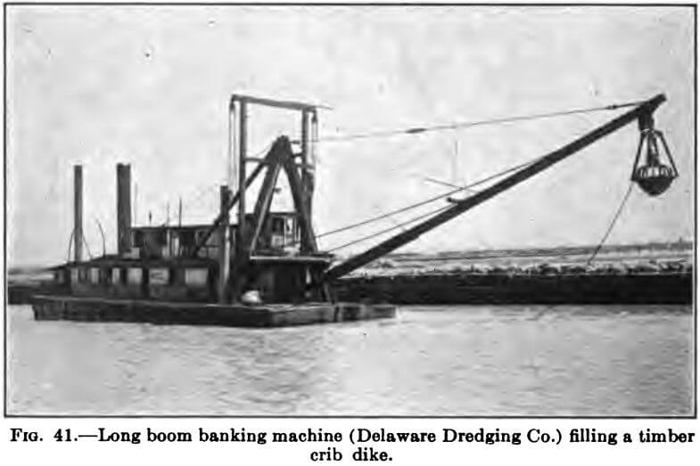
The first is simply a mound of earth cast up by a long-boom grapple dredge from the bottom soil. Although often employed with varying degrees of success, it is frequently of doubtful stability and permanence. The material of which it is built is saturated and suffers therefrom in angle of repose. It may be easily so soft as to be incapable of “standing up” above the water surface. Unless protected upon its slopes by more resistant material, it is easily scoured and melted away by wave and tide action. The depth of water in which it is to be built is an important factor.
The mud-fence is simply a tight vertical wall of continuous sheet piling, driven between guide wales, supported at intervals by round piles and stabilized against the thrust of the pumpings by spur or batter piles or by tie rods and anchorages. The sheeting may be a single thickness, or two layers, shiplapped, or Wakefield piling, depending upon the degree of tightness necessary to prevent leakage, as determined by the nature of the backing and pumpings. Wakefield is a built up tongue and groove piling, consisting of 3 planks fastened together as in Fig. 40. The fastening is effected by machine bolts, by wire spikes driven through
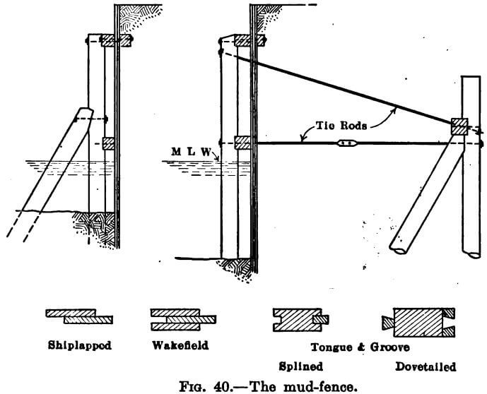
and clinched or by a combination of the two. A fourth method employs so-called splines, set in grooves in the sheet pile proper or nailed to the edge thereof. The dimensions of section and the length of the sheeting will depend upon the nature of the bottom, the depth of water, the height of the structure and the filling conditions. The size of the wales, spacing of round piles and anchorages or spur piles are determined from a study of the pressures acting upon the fence, by methods which will be outlined subsequently. The tie rods should be upset and provided with turnbuckles, by which an initial stress is set up in them to overcome the inaccuracies of framing the spur pile connection and to bring the surfaces into full bearing so that the resistance of the anchorage may be developed in the beginning before distortion takes place. This is very necessary to the preservation of the alignment of the retainer. The tie-rod washers are theoretically proportioned to distribute the bearing sufficiently to obviate local failure. Before commencing to pump into the basin, it is often advisable to back the mud fence with a bank of mud, or, if practicable, of more suitable material.
Conditions of greater depth and softer bottom may require the construction of a heavier and more expensive structure. Parallel mud fences, facing in opposite directions, almost as far apart as their height above the mud, tied across and braced by spur piles between them and filled with earth, form a substantial retainer which may prove best adapted to a particular problem.
The timber crib affords a useful expedient where the bottom is either of rock, prohibiting the penetration of piles, or of soft mud, affording scant lateral resistance for the sheet pile structure. A description of it is hardly necessary. It is simply a basket of squared, flitched or round timbers, successive layers of which are laid horizontally at right angles to each other, notched and spiked at the intersections, forming a cellular box which is subsequently filled with earth or preferably heavier material. It may be floored and lined with plank to secure greater fill-tightness, or the floor may be omitted and the lining planks driven down as sheeting into the mud below the crib. The bottom having been levelled as much as possible by dredging, the crib is built to fit the prepared surface. It may be constructed in the dry in sections and sunk by filling, or built up floating in the water, sinking under its own weight as the walls rise, and guided to the bed by guide piles. The width of the crib at the base is generally almost as great as the height. The rear face may be stepped, and the front face battered.
The stone dike, except under the most favorable conditions of market and working facilities will rarely prove economical. Little more need be said about it in this connection. It is generally quite pervious to the pumpings, requiring, for tightness a mud or other suitable backing.
By the bulkhead or marginal wharf is meant a retaining structure permitting deep water at its face for vessel flotation. It is not essentially a dike, but is mentioned here for the reason that, under certain conditions, the enclosing of an impounding basin by such a structure, the province of which is not only to serve as a dike, but also to make the property available for wharfage purposes, may prove to be the economical solution. The foregoing dikes, such as the timber crib or the parallel rows of sheeting will often involve considerable cost, entailing the expenditure of a large sum of money for a structure, the sole function of which is to serve as a dike, so that the enhanced value of the bulk-headed property may warrant the greater initial outlay. If the basin is ultimately to be used as a wharf property, it is obviously in the interest of economy to accomplish this end in one operation rather than subsequently to supplement a dike with a wharf structure, unless there be attenuating circumstances.
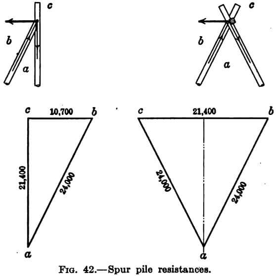
Spur Piles.—Of the above six types of wet dikes, it will readily be seen that Numbers 1, 4 and 5, and Number 3 partially, are gravity retainers, and that Numbers 2 and 6, and to some extent Number 3, employ the spur or batter pile to resist the overturning tendency. It would appear, therefore, that the subject of spur piles is of sufficient importance to merit discussion here. Moreover, the diversion, if it be such, is further excused by the tendency among some contractors and even engineers to give inadequate attention to the spur pile details both in design and construction. Not only is this true of the dike, but of bulkheading structures generally, wherever the spur pile is employed, and many failures may be attributed to this fact alone. In the first place, because of the expense of providing special inclined ways for driving the batter piles, they are frequently driven by tilting up the leads of vertical pile drivers, resulting in insufficient batter to develop the horizontal resistance required. An inclination of 30 degrees to the vertical is entirely practicable in the great majority of cases and should be insisted upon. Again, whether through failure to realize fully the nature and extent of the forces acting, or through the desire to economize in framing and hardware costs, the head of the spur pile is often inadequately retained to develop the full horizontal resistance.
Let us discuss for the moment the spur pile in general. Assume that a pile is driven on a batter of 1 to 2 to such penetration as to develop a safe axial bearing value of 12 tons or 24,000 pounds. The vertical component, Fig. 42, is about 21,400 pounds and the horizontal 10,700 pounds. The pile then is capable safely of resisting a horizontal thrust of 10,700 pounds if—and herein lies the difficulty— the head of the pile is held down by a force equal to the vertical component, 21,400 pounds. In bulkheads of the relieving platform type, this downward resistance to the upthrust of the spur pile, is furnished wholly or in part by the weight of the fill upon the platform, but in other types of retaining structure, such as the cases in point, or in marginal wharves of the above-water pile and platform design, it becomes necessary to depend upon the resistance to pulling of a vertical pile to which the spur pile is attached, and it is this attachment which merits emphasis.
If framed as in Fig. 40, page 133, the depth of “gain” in the plumb pile must be sufficient to give a horizontal bearing surface of such area as to keep the unit bearing
within the allowable limit. If the safe end-grain bearing value is 1000 pounds per sq. in., the area required for the above case is 21.4 sq. in., which, in a 14 inch pile, will obtain at a depth of about 3 inches. Moreover, the length of plumb pile above the notch must be great enough to preclude failure by shearing with the grain. It is not always practicable, however, to drive spur and plumb pile in such relative position as to permit a fastening of this kind. In many instances, the batter pile must be placed alongside a bent of vertical piles, in which position, the problem of sustaining its upward reaction often presents difficulties. It is manifestly not enough simply to bolt the spur and plumb pile together horizontally at their intersection, because, even though the bolt be of sufficient size to take the shear, the fastening will fail through the bending of the bolt and the crushing of the wood fibres in the bolt hole at the point of contact of the two piles. The most convenient and efficacious arrangement of this detail in high timber platform
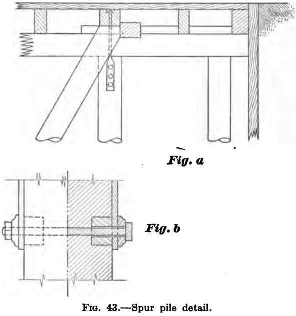
bulkheads, in so far as the vertical forces are concerned, is the capping of the spur piles with a timber running across the bent cap and called the “spur cap,” which transmits the upthrust to one of the plumb bearing piles of the bent, through a pair of strap bolts, Fig. 43. Even here, it frequently happens that the strap bolts themselves and their fastening to the bearing pile is not given sufficient attention. In the first place, if the reaction is to be transmitted to the plumb pile through the tension in two bolts, one on each side of the pile (as is generally required), the spur cap must be continuous over spur pile and bent cap, breaking joint somewhere between bents. In the second place, the bolts must be everywhere of sufficient net section to take the tension, and, finally, the attachment to the bearing pile must be adequate in shear and bearing-both in the metal and timber. It is the latter, the bearing of the bolts in the holes through the pile, that proves most troublesome.
Referring to the assumed problem, the stress in each strap bolt is 10,700 pounds, requiring 10.7 sq. in. of end grain bearing for a unit value of 1,000 pounds per sq. in. Using 7/8 in. bolts through the pile from strap to strap, this means that three would be required, since it is hardly safe to assume that a length of hole more than four times the diameter of the bolt is effective in taking the bearing because of the bending of the bolt. It is next to impossible, however, to bore three holes through a 14 in. pile such that they will be opposite the bolt holes in each strap on each side. Lag screws may be substituted, but are not wholly satisfactory. A scheme devised by the author employs a single heavy bolt, about 1¼ in. in diameter, and two cast iron spools to furnish the required bearing surface, one at each side, Fig. 43, page 138. The spools are cast with a slight taper and driven snugly into holes bored by a 3¼ in. auger to the depth required. The pile surface under the straps must be freed of bark before placing them. This makes a positive and inexpensive fastening, easily installed.
Pressures on Wet Dikes.—In the design of dikes for enclosing a submerged basin, there are three conditions of loading to be considered, although all three may not necessarily obtain in all dikes, not in all portions of the length of one specific dike.
They are as follows:
Case I.—The pressure exerted by the dredged material, when in a saturated or semi-fluid condition, while the hydraulic filling is still in progress.
Case II.—The hydrostatic pressure of a head of contained water alone, which, having dropped its suspended matter, is still retained within the basin up to the elevation of the crest of the waste-weir.
Case III.—The pressure of the ultimate loading, when the completely filled basin, having drained and dried out, is subject to the weight of surcharge or of extraneous dead or live loads.
In all three cases, the internal pressure is partly counteracted by the external hydrostatic pressure, the critical loading obtaining when the latter is a minimum at the time of extreme low water.
In the first case, the controlling factors are the nature of the material dredged, the size and shape of the basin and the manner and rate of filling. Usually, in the process of filling the basin, the discharge pipe-line is lengthened by the addition of pipe sections only as the fill at its mouth is brought up to final grade, resulting, after a time, in a basin filled to grade and dry in the vicinity of the point of initial discharge, from which the surface of the fill slopes gently down beneath the contained water to the original bottom in the remoter portions of the basin, where simply a head of water exists from the original bottom of the basin to the elevation of the height of the crest at the sluice. As the pumping continues, the inclined surface of the fill progresses toward the sluice, tending constantly to decrease the surface area of the contained water and thus necessitating raising the elevation of the water by the placing of additional weir boards in the sluice-box in order that the submerged or impounding area may remain sufficiently large to fulfill its function of precipitation necessary to a reasonably clear effluent. If the dredgings consist entirely of alluvial silt or river mud, this surface slope will be very flat and a large impounding area required. If the material be of uniformly heavy material, the slope will be sharper, permitting a smaller basin. Finally, if the pumpings be a mixture of mud or silt and some heavier material such as coarse sand, the effect of the hydraulic handling will be to segregate the two, the sand being deposited quickly near the mouth of the discharge pipe, so that only the more remote portions of the dike will receive the greater thrust of mud alone. Even if mud be the sole element of the pumpings, the area of the basin may be so great and the rate of filling so slow that, before the fill attains its final elevation, the earlier pumpings near the bottom will have had opportunity to compact or set to a certain extent, acquiring an appreciable angle of repose and lessening the pressure. More especially will this be true if the basin be drained at frequent intervals.
The greatest possible pressure of the first condition of loading is that resulting from a filling of what is virtually liquid mud. River mud submerged or completely saturated has an angle of repose of zero, so that it exerts a fluid pressure which is much greater than that of water because of the greater weight of the liquid. Whether or not the dike will be subjected to a total head of liquid mud, the engineer must predetermine from a study of the foregoing elements.
The pressure of Case II can be the critical loading only when the pumped material is of such heavy nature as to deposit rapidly and exert a horizontal thrust less than that of the head of contained water. In such case, the maximum head will obtain when the basin is in an advanced stage of completion and the weir has been raised to or nearly to its full height.
The loading of Case III presupposes the subsequent use of the fill for commercial purposes, entailing the placing of heavy, quiet or moving loads upon its surface close to the dike.
The pressures resulting from the three conditions of loading will now be investigated.
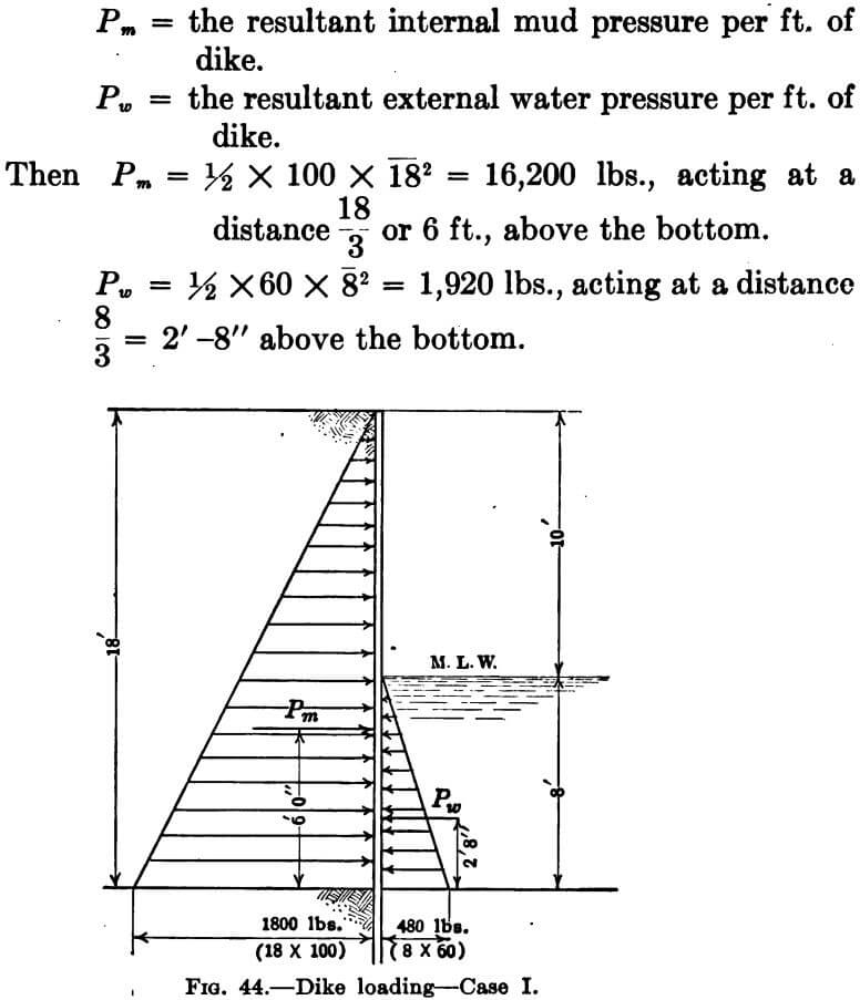
Case I.—Let us assume a dike built in 8 feet of water and rising 10 feet above the surface, subjected to a loading of liquid mud. We then have a retainer separating two fluids of different weights and heads, the mud emulsion on one side weighing 100 lbs. per cu. ft. with an 18 ft. head, and water on the outside weighing 60 lbs. per cu. ft. with a head of 8 ft., Fig. 44. in which
Case II.—Now suppose that the critical loading of the same dike be that of the second condition, i.e., hydrostatic pressure on both sides. The resultant internal pressure per foot of dike becomes ½ x 60 x 18² = 9,720 lbs., the external pressure and the point of application of each remaining the same as in Case I.
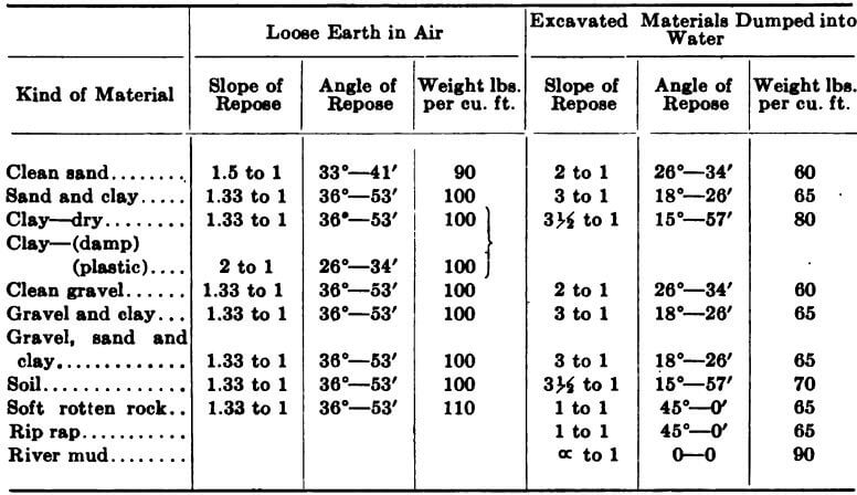
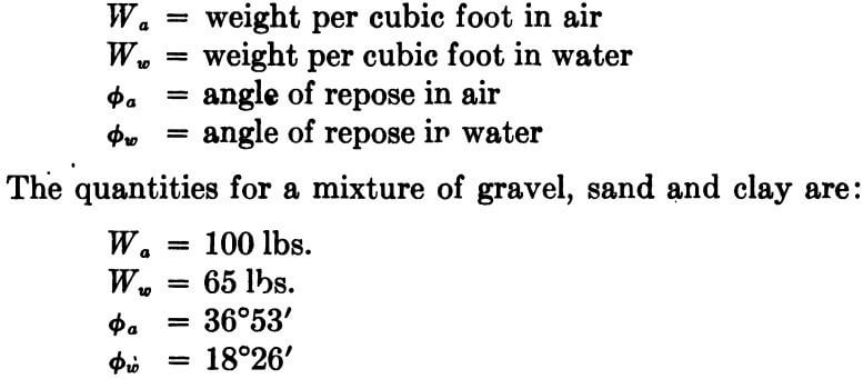
Case III.—Finally, let us apply the third or ultimate condition of loading to the dike, assuming that the filling be a mixture of gravel, sand and clay and that the live load surcharge equals 600 lbs. per sq. ft. The table, page 143, taken from the American Civil Engineers’ Hand Book (Merriman), gives the weight, slope and angle of repose of various materials both as loose earth in air and as excavated material dumped into water. Using the following notation:
The most workable formula for earth pressure, P, per foot of dike and one whose degree of accuracy is consistent with that of the other factors of our problem is
P = ½wh² tan² (45° — ½∅)
which assumes that, were the dike to be removed, the backing would fail by parting along the plane ac, Fig. 45a, called the plane of rupture, and making an angle with the vertical of 45° — ½∅ so that the horizontal thrust against the dike is caused by the tendency of the wedge abc to slide upon the plane ac, and is the horizontal component of a force paralleling the plane of rupture, the vertical component of which is the weight of the sliding wedge abc.
For one horizontal foot of wall, the quantities involved are:
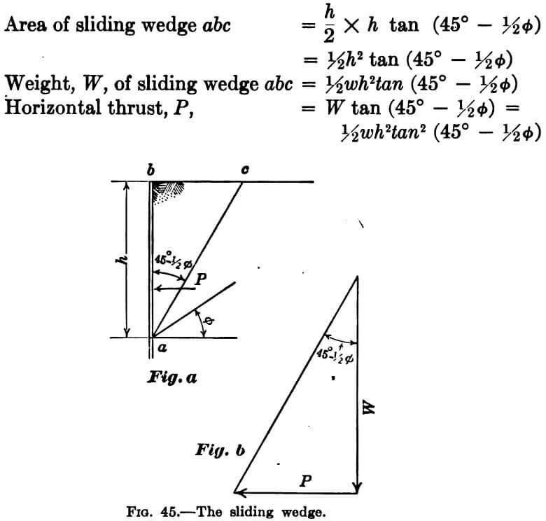
P may be found graphically, Fig. 45b, by laying off to scale on a vertical line the weight, W, of the sliding wedge and the angle of rupture, 45° — ½∅, then closing the triangle by a horizontal line, the length of which equals the thrust, P.
In the problem assumed, 45° – ½∅a = 45° – (36° 53′)/2 = 26°34′ and 45° – ½∅w = 45° – (18°26′)/2 = 35°47′. The conditions then are as shown in Fig. 46.
The weight of the sliding wedge is made up of three parts:
- the area abc in sq. ft. x Ww
- the area bdefc in sq. ft. x Wa
- the length df in ft. x 600.
and, if the figure is drawn accurately with scale and protractor, the areas may be found from scaled dimensions.
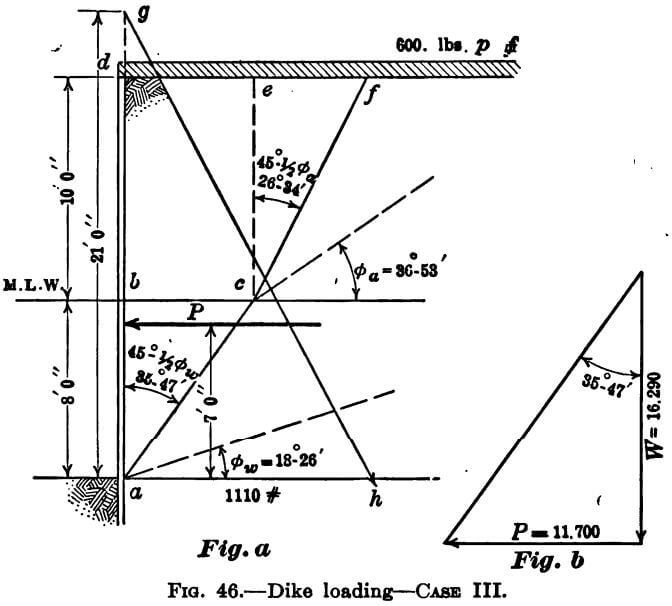
The total weight of the composite sliding wedge and the angle of rupture of the lowest stratum determine the magnitude of the horizontal thrust. The total weight is
Then, graphically, as before,
P = 11,700 lbs.
In this instance, the solution yields the net thrust, as the water pressure has already in effect been deducted by 10 reason of the fact that the quantities used for the submerged stratum were submerged quantities. The pressure to be resisted by the wall is, therefore, 11,700 lbs.
The formulae will of course yield the same answer without graphical aid.
Design.—In those dikes not of the gravity type, it now remains to ascertain the stresses in the sheet piling and the proportion of the thrust transmitted thereby to the above water structure. The most convenient treatment is by the method of equivalent fluid pressure, i.e. the determination of the weight of a hypothetical fluid which will produce the same thrust P both in magnitude and point of application. Resultant earth pressures act at a point somewhere between one-third and one-half the height of the wall from the bottom. Where the live load surcharge is considerable, the point of application may be safely assumed at 0.4 the height. In our problem, this point will be 0.4 x 18 or 7.2 feet from the bottom. Call it 7 feet even. Hydrostatic resultant pressures, however, act at one-third of the height. The head, therefore, of the so-called equivalent fluid will, in this case, be 3 x 7 x or 21 feet, and the resultant pressure = wh²/2 = w x 21²/2 = 220.5w. Equating this to the above value of P and solving for w, we find that a fluid weighing 53 pounds per cubic foot will exert an equivalent thrust. The unit pressure at the base of the wall = wh = 53 x 21 = 1110 lbs. Again, in the Fig. 46, lay this off to scale and draw the triangle of fluid pressures, agh, from which the unit pressure at any point of the height may be scaled and the stresses in the structure analyzed. In the case of the mud fence, the first step from this point will be the determination of the proportion of the thrust carried by the tie rods and spur piles, whence, knowing this reaction, the bending moment in the sheet piling maybe found.
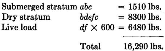
As a more complete illustration of the problem subsequent to the evolution of the pressure triangle of the equivalent fluid, let us discuss the case of the relieving-platform, sheet-pile bulkhead, Fig. 47.
The sheeting is a vertical beam fixed at the lower end at A and supported at the top, B. The point of fixture, A,
will be at or a short distance below the mud line, depending upon the resistant qualities of the material comprising the
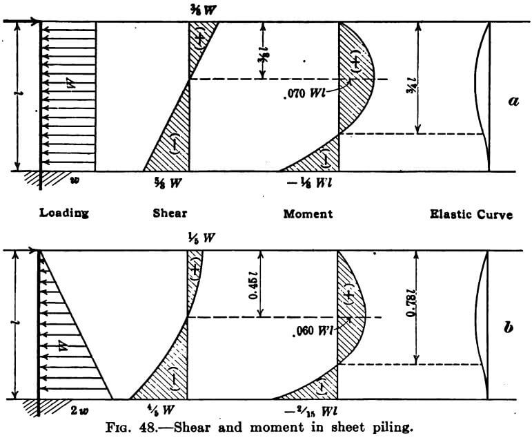
bottom. For the mixture of gravel, sand and clay, we will assume a value of 2 feet. The beam AB is resisting the trapezoid of pressures abde, and the problem is to find the reactions at A and B and the bending moment in the sheeting. To this end, consider the beam loading in two parts; 1st, the uniform load, bdfa, and, 2nd, the uniformly varying load 0 to fc pictured by the triangle def, and ascertain, independently, the end reactions, the moments and shear in the beam due to each load. Then by combining the two, the critical stresses in the sheeting may be found. Fig. 48a, gives the diagrams for the uniform load, abdf, and Fig. 48b, for the variable load, def.
Mechanics of a Beam, of length Z, fixed at one end and supported at the other, carrying a total load, wl, varying uniformly from zero at the supported end to 2w (twice the average load per foot, w) at the fixed end.
If R1 = the reaction at the left or supported end, the bending moment, Mx, at any section, distant x from R1, is
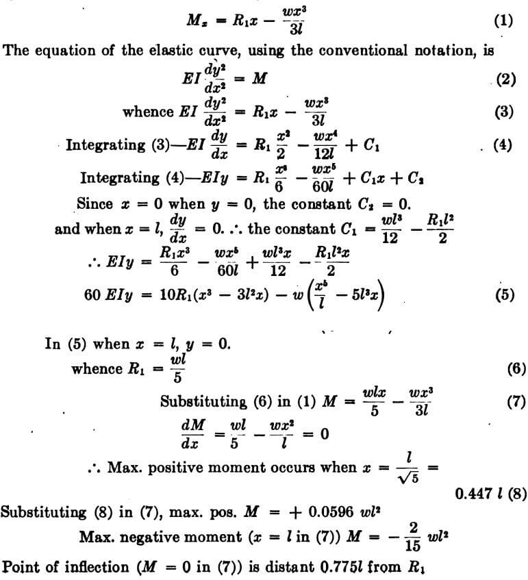
Bearing in mind, then, that the W of the first condition, which we will call W1, equals bd = af, and the W of the second, called W2, equals the average unit load, or ½fc, the combined quantities for the total load abdef are:
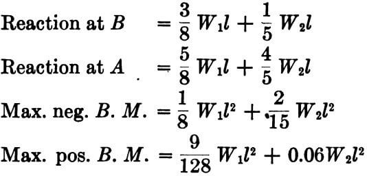
the last being not absolutely true, due to the fact that the point of max. pos. B. M. is not coincident in the two cases. However, it is sufficiently accurate to be consistent with the other assumptions, and the error is on the side of safety.
The total pressure resisted by the bulkhead structure is the sum of the reaction at B as above, plus the triangle bed. Whereas the assumption that the point of application of the resultant pressure, for the usual average live load surcharge, is 0.4 of the height from the base is sufficiently accurate for the design of the structures cited, for the larger sea walls, an investigation of the location of that point becomes necessary. Such a discussion, however, is neither commensurate with the scope of this book, nor apropos of our subject title. Mr. S. W. Hoag, in the Proceedings of the Municipal Engineers of the City of New York, 1905, describes in detail the two methods of pressure calculation used by the Department of Docks in New York. The more recent of the two reduces the several component substances of the sliding wedge to a single homogeneous material, that at the base of the wall, whose plane of rupture determines the direction of the pressure. The true centre of gravity of the sliding wedge then is the centre of gravity of this reduced polygonal figure, and the point at which a line drawn through it parallel to the plane of rupture interprets the perpendicular at the back of the wall is the point of application of the horizontal thrust.
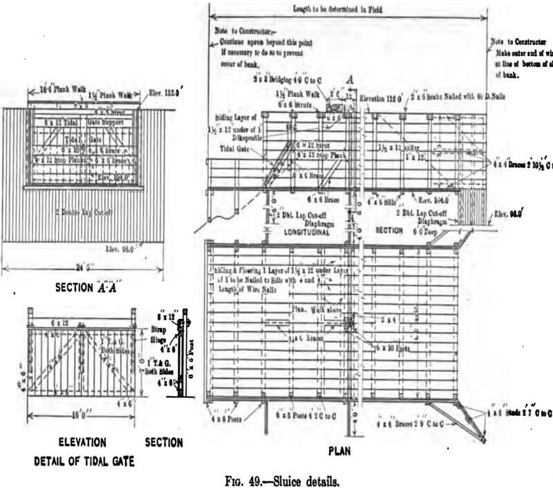
Sluiceways.—The structure through which the pumped water escapes from the impounding basin is called variously the sluiceway, sluicebox, sluice or waste-weir. The principal parts of a complete sluice are, first, the box proper, consisting of floor and sides to retain the dike material; second, one or more sheet pile cut-off walls to prevent the percolation of water (and resultant scour) through the dike under and alongside the sluice-box proper; third, the weir itself, built up of a series of planks, set loosely in vertical grooves so that the elevation of the crest of the weir may be raised from time to time by placing additional weir boards as the filling progresses, or lowered to drain the basin; fourth, the tide gates, which are, in effect, large flap valves, opening in the direction of the effluent and preventing the back flow into the basin of outside water under heads created by tides, freshets, or other causes; fifth, a walkway across the sluice for the convenience of the bank patrol and to facilitate the addition or removal of weir boards. While the details of design vary materially with the various types of dike in which the sluice is built, the above features must all be taken care of. Fig. 49, page 151, shows the type of sluice used for earth embankments in connection with the dredging appurtenant to the construction of the Hog Island Shipyard.
The argument used for the determination of pressure against the dike is applicable also to the sluice. In very soft material, it may be necessary to found the structure upon piles. Revetment work of sand bags or rip rap upon the adjacent slopes may be required in some instances. A sluiceway built through a crib or mud-fence dike may require an outboard apron to prevent back scour.
The elevation of the floor of the sluice will be such that the basin can be drained to the minimum desired level. The requisite width of the box, or length of the weir, depends upon the number and capacity of the dredges discharging into the basin. It is desirable that the head of water on the weir crest be not greater than about 6 to 8 inches, in order that the disturbing influences of high
velocity and scour be reduced to a minimum. Thus, the customary width of sluices is about as follows:
12 to 16 feet for one 20 inch dredge or equivalent
30 feet for two 20 inch dredges or equivalent
40 feet for three 20 inch dredges or equivalent
Let us investigate a sluice designed to take the output of one 20 inch machine with an average discharge through the length of line used of 22.0 cu. ft. per second. Francis’ weir formula
Q = 3.33 bH3/2
gives results sufficiently close for our purpose, where
Q = the discharge in second feet = 22.0
b = length of crest = width of sluice
H = head above the crest measured some distance back from the crest.
Then, for the maximum condition of H = 8 in.
b = Q/3.33 x H3/2
b = 22.0/3.33 x (0.67)3/2
from which, b = 12 ft. (approx.)
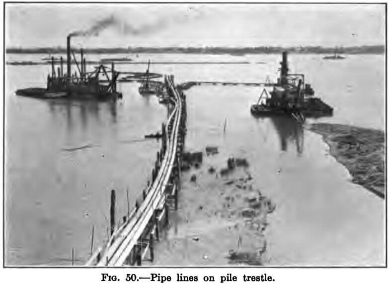
Pipe Lines.—The shore pipe is most conveniently laid upon the surface of the ground, but the necessity often arises for the depression of the pipe under roadway and track crossings and for the elevation of the line upon trestles in crossing swamp land, or submerged flats on which the water is too shallow to float pontoons. Such depression generally requires no special structure, as the usual pipe will stand up under the load if at least 9 inches below the base of rail and if the two adjacent ties are spread to distribute the load to either side. Pipe trestles over water are generally built by driving two-pile bents about 12 feet on centres, with the piles from 6 to 8 feet apart in the bents, and clamping the two with one or two horizontal members of 3 x 12 or 4 x 12, which support the pipe. As a rule no transverse or longitudinal bracing is necessary except in the last 3 to 6 bents and in the ball joint platform, where the pull exerted by the pontoon line must be taken care of. For the same reason, a short stretch of the shore line at the point of connection of shore and pontoon lines is tied together with chain or cable.
For maximum efficiency, the land pipe line should be laid out with minimum curvature, horizontally and vertically, and, especially, should abrupt changes in direction be avoided.
The location and length of pipe trestles must generally be such as to permit the dredge to reach all parts of the zone ascribed to her without an impracticable length or curvature of the pontoon lines. Machines, unless built for a special purpose, are seldom equipped with more than 1200 feet of pontoon line.