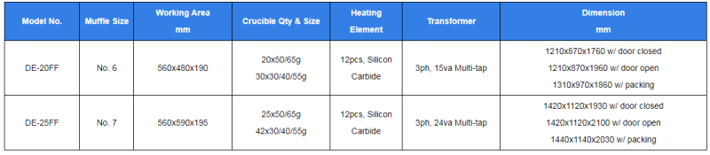
This 25 place fusion (assay) furnace is electrically powers by a 24000 Watt heating element allowing it to reach and hold a temperature of 1200 degrees C (2200 F).
With a working area of 56 cm deep X 59 cm wide X 19.5 cm tall, this furnace will hold:
This furnace has an easy to use main rotary on/off switch.
It is heated by 12 elements mounted in the side walls. It is ideally suited to continuous running as this will prolong the life of the elements.
Temperature is monitored and modulated automatically by a Type K thermocouple system and Omron temperature controller, pre-set for a maximum temperature of 1200 degrees Celsius. This controller is simple to operate, and has a 2-level display (PV and SV). that shows actual temperature as well as the temperature the furnace is set to.
The doors have Omron door switches installed that will automatically cut power to the heating elements when any door is opened.
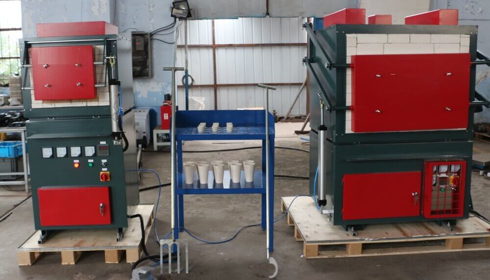
Product gallery
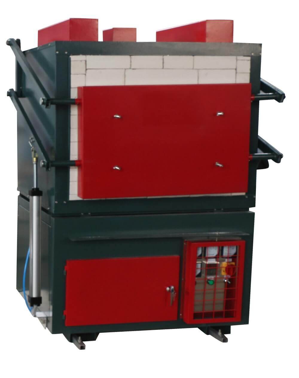
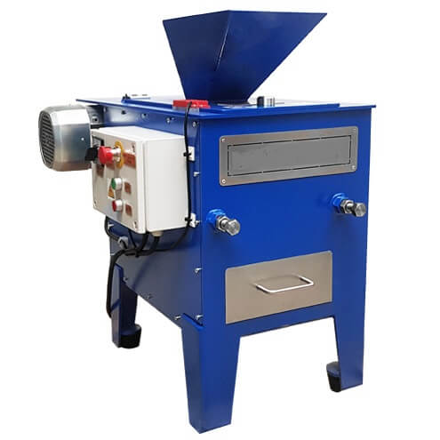
The external structure of the furnace shell is made of galvanized steel sheets mounted on the bracket on the surface of the shell made of steel pipe. The blue paint; Furnace Body: the inner surface of the furnace is made of alumina refractory brick, and the back is insulated refractory brick; Heating mode and rated energy consumption; Temperature control mode: electric, automatic control, the highest temperature can reach 1200 degrees; Temperature sensor: “K” thermocouple, high measurement accuracy;Power supply: the furnace body is equipped with a 10A, single-phase cable and plug, and the power load is 5A; Pneumatic control furnace door opening and closing, foot switch conveniently for users to operate, avoid high temperature and hot environment caused by security risks.
STRUCTURAL OVERVIEW
This furnace has an easy to use main rotary on/off switch.
It is heated by 12 elements mounted in the side walls. It is ideally suited to continuous running as this will prolong the life of the elements.
Temperature is monitored and modulated automatically by a Type K thermocouple system and Omron temperature controller, pre-set for a maximum temperature of 1200 degrees Celsius. This controller is simple to operate, and has a 2-level display (PV and SV). that shows actual temperature as well as the temperature the furnace is set to.
The doors have Omron door switches installed that will automatically cut power to the heating elements when any door is opened.
INSTALLATION PROCEDURE
Unpack furnace from crate and store in dry area. The furnace usually has timber supports installed inside for transport. Remove before operation.
2.1 Furnace requires minimum 1 meter space around it to carry out maintenance / repairs.
2.2 Install fuel supply. This must be carried out by a qualified technical person.
2.3 Air is required to run the pneumatics for door operation. Connect air supply to the filter on the furnace.
2.4 Electrical connection is 3 phase with Earth. Connection is made at the terminal strip inside electrical cabinet. Once connection is made, before turning on power, check all other connections as they may have come loose during transport.
2.5 Before starting please check whether all exhaust ducting is in place.
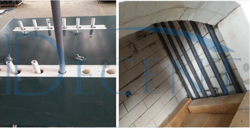
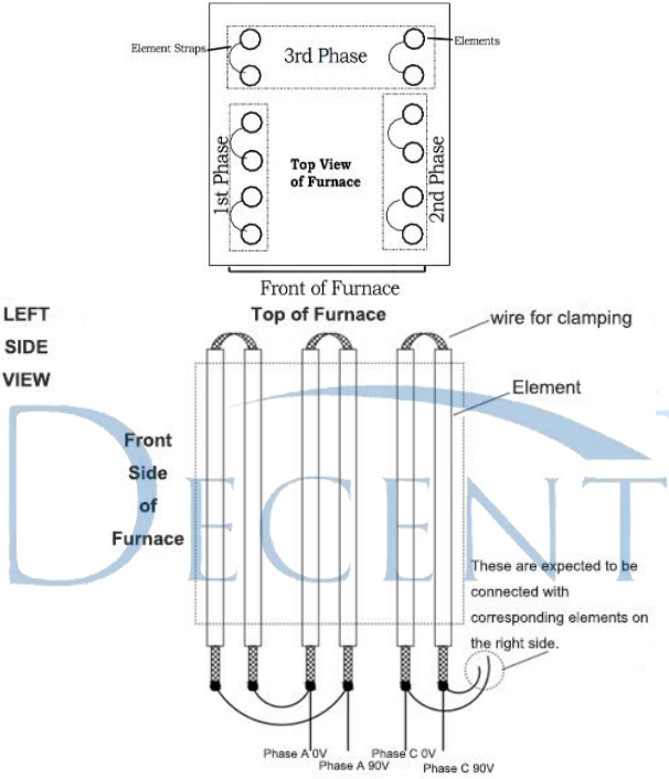
INSTALLING ELEMENTS
3.1 When installing elements be careful not to force any into position.
3.2 The elements are fragile, and if there is too much pressure on them or if they hit the floor of the furnace they may break.
3.3 It is best to install the elements before the muffle chamber is in if possible, as then you can have two people to guide the elements through the bottom holes.
3.4 When installing, make sure that the elements sit flat on the element holder underneath the body.
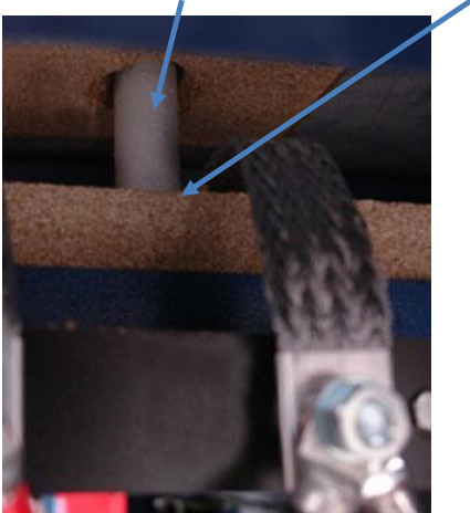
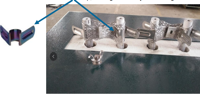
3.5 Once all elements have been installed, wrap the element straps around the elements and secure with an Element Clip, making sure that you have a good connection.
3.6 The lower end is connected to the power supply and clamped with a nut.
3.7 Check that none of the straps and clips are touching the frame or the top cover.
3.8 Check that all nuts holding the connections (straps) are tight.
3.9 Install the top and side guards of the furnace.
Remarks:
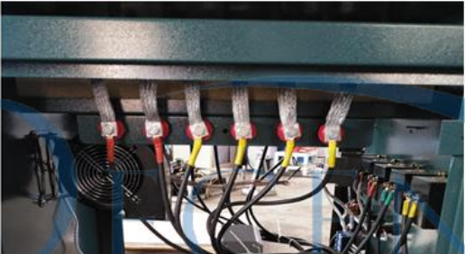
Element connections are from front to back.
The first 4 elements are 1st or 2nd phase (depending on the left or right side of the furnace) and the rear 2 elements are part of the 3rd phase (on both sides).
SILICON CARBIDE ELEMENTS
Generally a heating element made of silicon carbide is gradually oxidised due to its application over long periods, increasing its electrical resistance; that is, aging results. This is due to the partial oxidisation of SiC, which is formed into SiO2, diminishing the electrical conductivity of SiC according to the reaction.
SiC + 2O2 → SiO2 + CO2
To prevent oxidisation and to preclude an increase in electrical resistance, the surface is covered with a film coating, which, being stable without comparison, helps minimise aging and ensures a considerably longer life. When the electrical resistance has increased to about five times the incipient value, the service life of a heating element may be considered expired. In actual application its aging speed depends on the applicable temperature, watt density, operating type (continuous or intermittent), atmosphere in the furnace, and so on.
NEW MUFFLE START-UP FROM COLD PROCEDURE
Regular maintenance is required to make sure furnace is running correctly.
When staring a furnace up with a new muffle installed or starting the furnace from cold you must do so slowly. This is to reduce any cracking in the cold muffle of furnace.
MUFFLE START UP FROM COLD
Once muffle is in place and rear vent has been installed into furnace:
Start furnace and set to 250°C;
Run for a minimum of 2 hours;
Set temperature to 500 °C and run for another 1 hour;
Set temperature to 800 °C and run for another 1 hour;
Set temperature to 1200 °C and run for another 1 hour;
Set temperature to normal running conditions and muffle is ready for use.
MAINTENANCE
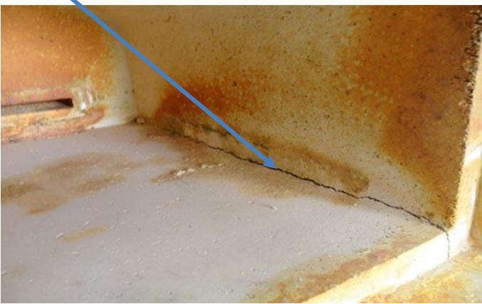
To do this and to extend the life of your muffle and furnace, regularly check that muffle chamber has no cracks, if so then seal with some refractory cement. Make sure a floor tile is always installed, with about 15mm of Bone Ash underneath it. Regularly scrape and clean the floor tile. If there is build-up on one side, flip the tile over to double its life. Change floor tile regularly.
Keep the floor areas around the furnace clean and free of dirt, as it will layer onto the transformer and control equipment. This chokes the equipment and makes it run hotter and it may over heat.
Remember a chamber is a consumable item in a furnace. You must change a chamber out at least 2-3 times a year if looked after correctly. If little or no maintenance is done on a furnace, the chamber can last as little as 1 month. If the chamber is left unchanged, the brick work of the furnace will be eaten away. This will severely reduce the life of your furnace.
SUMMARY
A good clean combustion chamber will allow the furnace to run efficiently. To do this and to extend the life of your muffle and furnace, regularly check that muffle chamber has no cracks, if so then seal with some refractory cement.
Make sure a floor tile is always installed, with about 15mm of Bone Ash underneath it. Keep the back Vent clean and clear, and change it when needed. Regularly scrape and clean the floor tile. If there is build up on one side, flip the tile over to double its life. Change floor tile regularly. Regular maintenance is required to make sure furnace is running correctly. Maintain Door ceramic blanket and change it if in poor condition.