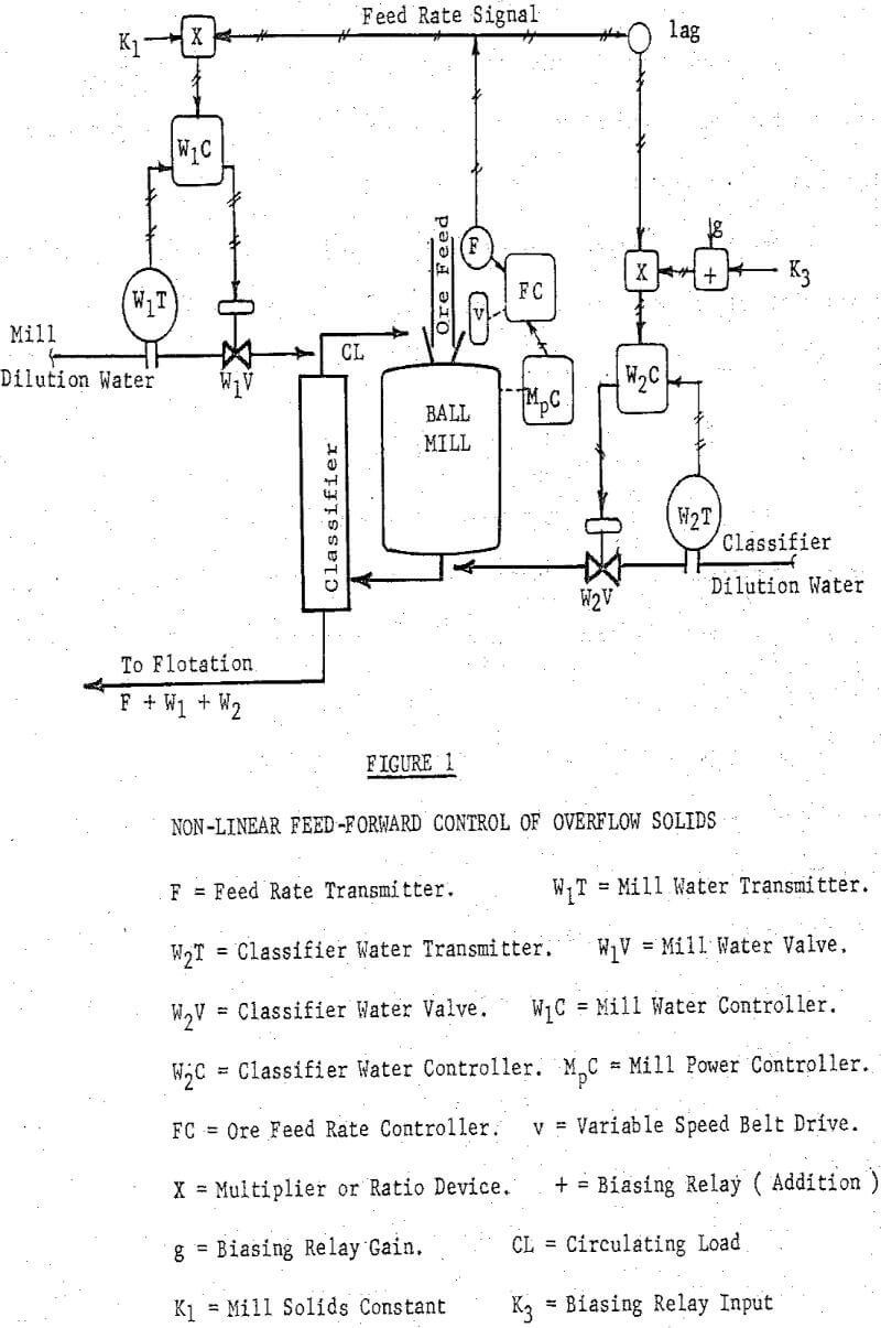
Feed-forward control ( i.e. the forward flow of information in a control system ) is a simple and flexible approach to over-all control of a ball mill-rake classifier grinding circuit. The system described here uses mill power, feed rate, mill dilution water flow rate, and classifier dilution water flow rate only, to control mill load, throughput, mill solids, and classifier solids as well as classifier overflow grind.
The control system was installed on a 9 x 9 Marcy ball mill in closed circuit with an Akins duplex spiral type classifier. Ball Mill Horsepower- is measured by means of a thermal converter, amplified and transduced with an EMF – Air Current converter to give a 3 – 15 psig or 4 – 20 ma signal representing about 410 to 485 horsepower.
Ore Feed Rate- is obtained by inputting the belt speed signal and belt load j signal to a multiplier. Scaling is done on the speed transmitter. The output signal is proportional to the ore feed rate. ( An electronic feed rate measurement based on a magnetic pick-up and a frequency-current transducer was later evaluated and found to be slightly more accurate and less costly.)
Mill Load Control- the power to the mill is kept constant by adjusting the ore feed tonnage. Control is on the overload side of the H.P vs. load curve and is achieved by a standard two mode controller cascaded into a feed rate controller.
Mill Water Ratio Control of Mill Solids- the mill water ratio controller receives its set point continuously through a ratio device via the feed rate signal to maintain a constant gallons per ton of mill dilution water.
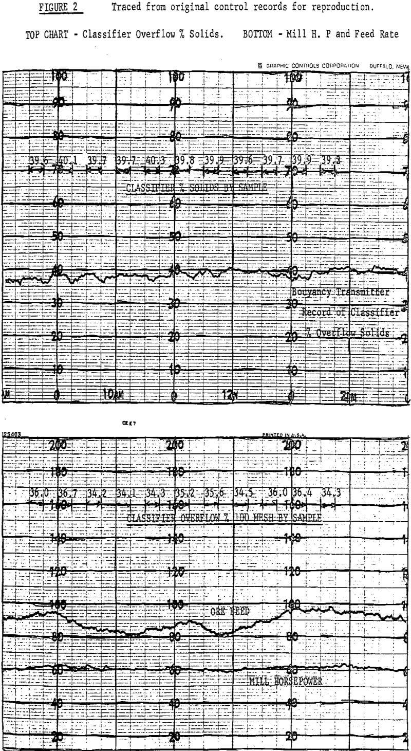
A 24 hour evaluation was made on the installed non-linear system under automatic control. A one half hour composite was taken from the classifier overflow every hour and carefully screened. Spot checks of grind and operating adjustments were made during the first 3 hours ( the value for bias gain had previously been determined ) to bring the circuit to a 36% plus 100 mesh target. The system held the overflow grind to better than ±1 % for the remaining period with changes in feed tonnage of 22%. No further operating adjustments were made during the period. Spot checks showed that the grind remained on target for several days afterward.
A static mathematical model can be written based on the control configuration and the test results.
For the Mill Load Control
M= K0 Mp = (f) F = Ks
Where: M = Mill Load
Mp = Mill Power
K0 = Scaling Factor
F = Mill Ore Feed Rate in Tons per Hour
Ks = Mill Load Set Point
The control of the mill load by horsepower works extremely well on the grate mill described, but the application of the same technique to an overflow mill lacked repeatability and a different method had to be used. In the overflow mill, the classifier horsepower signal and the ore feed rate signal are summed and scaled to give an indication of the total load in the mill. The rest of the system is essentially the same.


