Table of Contents
A fully-instrumented driving mechanism has been constructed to study the power, aerating and solid suspension characteristics of several laboratory flotation machines.
Machines operating over normal flotation speed ranges give constant power numbers in liquid systems indicating that they operate under fully baffled turbulent flow conditions. Owing to lack of geometrical scaling, power numbers for different sizes of cells of the same make are different. Even larger differences occur between cells of different manufactures. For a given impeller, varying the tank size did not significantly affect the power consumption. Tank geometry and baffling has a slight effect on power consumption with shrouded impellers.
Apparatus and Experimental Details
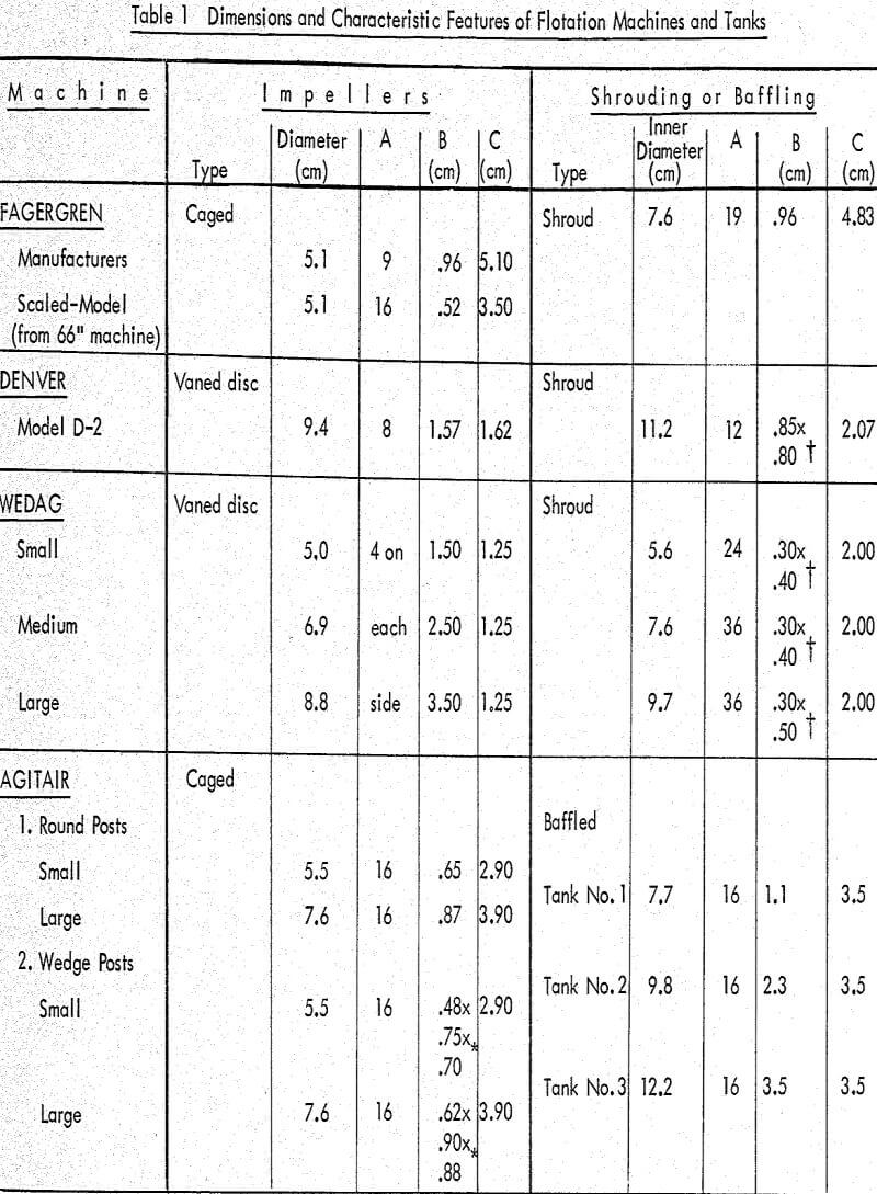
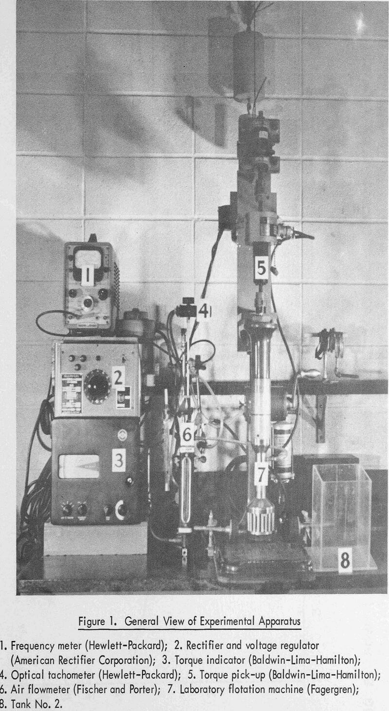
The driving mechanism was equipped with adapters for interchanging impellers and shroudings and several tank designs and sizes were available so that this unit could be converted from a simple agitator to any kind of laboratory flotation machine (Table 1). A strain gauge torque measuring device and a phototachometer were built into the driving mechanism, and speed variation was obtained by means of a DC motor with a rectifier and voltage regulator. These experimental facilities represented a considerable improvement over previous work in which power and speed were measured by means of a watt meter and stroboscope respectively, and speed variation obtained by means of spring loaded split pulleys. Air flow was measured by a Tri-flat flowmeter. It was estimated that the accuracy of torque, speed and air flow measurement was about ±2 percent.
The only matter requiring comment is the manner in which net power was obtained. Idling torque was measured both before and after each individual measurement of gross torque and only those values of gross torque obtained under constant idling torque conditions were accepted. Power was calculated from the measured net torque and speed. The entire torque measuring assembly was calibrated frequently by applying known torque increments under static loading conditions.
Liquid System
It has been shown that fully baffled mixing systems can be correlated by the dimensionless groups: power number, Np, and Reynolds number, NRe, defined thus:
where P is power consumption, N is rotational speed, D is impeller diameter, p is fluid density and µ is fluid absolute viscosity. The power number has the same physical significance as the resistance coefficient, F/pv², where F is resistive force per unit area and v is velocity, being the ratio of resistive to inertia forces.
Because the power is related to the net change in the tangential velocity component imparted by the impeller to the fluid, the power number reflects the flow straightening characteristics of the vessel and baffling on the fluid.
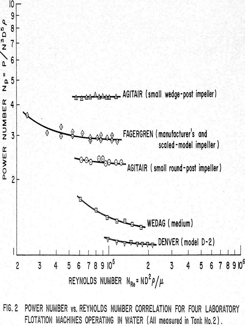
The correlations for four laboratory flotation machines are shown in Figure 2. For purposes of comparison, the power number for the Mixco impeller operating in a fully baffled tank is 6.8 at NRe = 10 5. Generally, Np for the shrouded impellers was not affected by moderate changes in T/D and C/D. In contrast, the Agitair system did show a strong dependence on C/D, Np increasing as C/D increased, and the wedge post impeller gave decreasing Np values as T/D increased. At NRe∼10 5 the Np value for the small and medium Wedag impellers was about 1.3 – 1.4, but for the large impeller it decreased to about 0.9. As indicated in Table 1, these impellers are not geometrically scaled in that the height of the blades and the thickness of the metal of construction is the same in all three.
Liquid-Air System
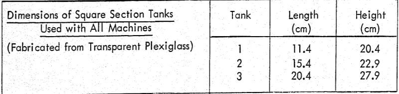
PL is the power consumption in liquid and PAL is the power consumption in the aerated system when the impeller is rotating at the same speed as in the non-aerated system. The air flow number is the dimensionless group QA/ND³ where QA is the air flow rate at atmospheric pressure. It was found in all cases that the power ratio did not decrease immediately as NQ exceeded zero, but remained constant until NQ∼10-³ and then decreased as NQ increased further.
The steep and extensive decline exhibited by the Wedag machine, which was the subject of earlier investigations, is now seen to be atypical. It should be noted in connection with Figure 3 that the range covered by NQ and PAL/PL is considerably wider than obtains in effective flotation operations since extreme values of QA and N were included in determining the curves.
Air flow QA enters the system at atmospheric pressure and is related to the air flow at the impeller by the mass balance equation
QAPA = QaPa……………………………………………………………………(3)
where pA is the density of air at atmospheric pressure, and Qa is the flow rate of air at the density of air in the impeller zone pa. Owing to pressure gradients existing in the impeller zone, pa is a mean value. It can be shown that the density in the impeller zone pi is given by
where QL is the flow rate of liquid of density PL, and z is a term related to the concentration of air in the impeller zone; if the fraction of recirculated air is k then z = 1 + k.
With some algebraic manipulation, and noting that the ratios pA/pL and pa/pL are neglibible (∼10-³ it can be shown that equations (3) and (4) give
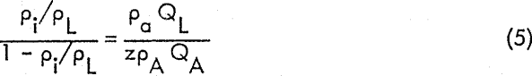
It is assumed that the impeller speed range under consideration is such that power number, Np, defined in equation (1) for the non-aerated system is constant. For ease of reference P and p in equation (1) are replaced by PL and pL respectively in order to specify the phases involved. The requirement of constancy is readily obtained by working in the range Np>10 4 and ensuring adequate baffling. It is further assumed that the value of Np is the same for both the aerated and non-aerated systems, other things being equal. This is an assumption; it has not yet been established. Thus,
PAL/PL = pi/pL………………………………………………………..(6)
Hence, using equation (6) in (5),
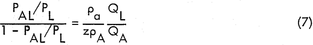
It is necessary to obtain a relationship between liquid flow, air flow and impeller speed so that the unknown QL in equation (7) can be eliminated. Previously, a relationship for total fluid flow QF was used
Qf ∝ ND³……………………………………………………..(8)
which was modified for the presence of air to the form
QL + qQa = fND³…………………………………………….(9)
where q was a term taking into account necessary modifications in equation (8) due to the presence of air – such factors as relative motion between the impeller and adjacent fluid elements (slippage). It is emphasized that equation (9) was not based on any direct experimental evidence; it was merely a plausible assumption. Eliminating QL between equations (7) and (9) and replacing Qa with QA using equation (3) gives
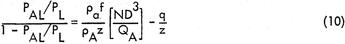
Equation (10) may be written in alternative form
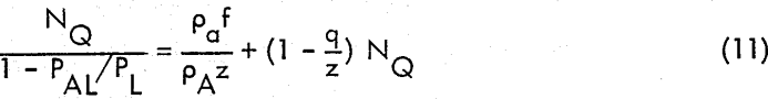
which, along with specific assumptions for the values of q and z was used previously. Equation (10) is preferred, however, because it confines the power ratio to one side of the equation and the flow number to the other, so that when the power ratio changes little there is no danger of misinterpretation by plotting NQ versus NQ as with equation (11).
Liquid-Solid System
There are two important interrelated conditions to consider in dealing with the liquid-solid system. The first concerns suspension, that is, lifting the solids off the tank bottom, and the second dispersion, that is, distributing the suspended solids into the tank. The extent of both of these conditions must be stated in order to define the state which obtains in a liquid-solid system in a particular agitation regime. For example, although suspension may be incomplete it is possible for the material which is in suspension to be fully dispersed.
Two special cases have been described in the literature; (i) full suspension, and (ii) full dispersion following full suspension. Zweitering’s results can be related by the Froude group, Reynolds number and several geometrical ratios in order to correlate the conditions for the first case. With the same solid, fluid, solid concentration, particle size, and different but scaled tanks and impellers, it can be shown that ND ∝ D 0.15. Pavlushenko studied the requirements for the second case and his relationship can be shown to lead to ND ∝ D 0.4.
A common scale-up criterion specifies maintenance of constant power intensity (power per unit volume), and, if power number, system geometrical ratios, and solids concentration are constant, this rule can be shown to be equivalent to ND ∝ D 1/3. This manner of variation of impeller peripheral speed with system size is within the range delineated by the two special cases mentioned above. Weisman and Efferding have reported suspension data which can be handled by a constant power intensity rule.
Flotation machine scale-up is a problem with two aspects. The manufacturer’s task is to provide cells with a range of capacities capable of producing similar and optimum metallurgical results with similar pulps; the operator has to discover the operating conditions under which this can be accomplished. With the ore parameters, throughput and chemical treatment determined, the remaining variables with which to achieve the desired conditions are N and Q.