
Table of Contents
Dredge Hull
Among dredging hands, the “ hull ”—namely, “ port ” and “ starboard ” pontoons tied together—is usually termed the “ pontoon ” or “ pontoons.” The ordinary hull consists of two long, narrow pontoons, joined together for about a third of their length by a third small one, equal in width to that of the ladder well required. The two longitudinal sides of the small pontoon are really a portion of the inner or well sides of the two main pontoons. For river work, pontoons should be made longer in proportion to their width than for pond dredging; they are then more easily handled in swift currents.
In all pontoons, the bows should be well drawn in. This enables the corners to be well taken out without bringing the dredge at right
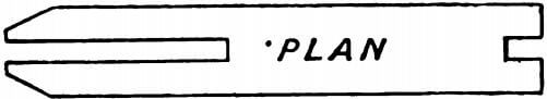
angles to the line of advance—a dangerous proceeding in a swift current.
In elevation the pontoons are much shorter on the bottom than on the deck. This allows of working close to the face forward,
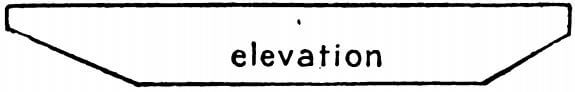
and prevents the stem being hampered by the tailings from the tables; besides, in a current, the forward end is given a certain amount of lift and buoyancy.
As the pontoons are practically a pair, joined together, great care in the design is necessary to obtain the required rigidity, especially in the cross section, as the greatest strain comes on the inward edges of the well, tending to cause the pontoons to buckle or hogg—that is, to assume a concavity on the deck and a convexity on the bottom.
The length of the hull, usually from 90 to 110 ft. long, is to a great extent fixed by the dredging depth. This is measured from the water line of the dredge to the cutting edge of the bucket, when the ladder is lying at an angle of 450 to the water line. Some dredging engineers measure what they term the “ maximum dredging depth ” at an angle of 35°; this makes a considerable difference, and in buying or ordering dredges, it is advisable to have this angle stated.
As regards material, wood has very largely replaced steel and iron. In Australia, timber hulls are exclusively used, also timber superstructure for earning the machinery. In some dredges, however, steel gantries are used, built of angle bars and plates. The timber for the hull framework, planking and deck is colonial hard-wood. In a number of instances, Oregon, and, in some cases, kauri has been employed for planking and decking. Where, owing to white ants and other destructive insects, it would not be advisable to use timber, it would be necessary to adopt iron and steel. For several reasons, steel is the material to be used in South Africa for hull construction. In New Zealand, the hull material is mostly Australian hardwood, chiefly blue gum, with kauri for planks and deck.
The main point in hull construction is stiffness to resist the concussions and jars the dredge has to withstand. Immense hardwood logs, 60—70 ft. long, with a mean diameter, perhaps, of 4 ft., firmly embedded for years in the wash, have to be lifted and carried clear of the dredge; huge boulders have to be negotiated; floods, at times rising 30—40 ft., rushing past at perilous pace and carrying islands of debris, have to be withstood, so that strength and stiffness are essential. Rigidity is increased by heavy transverse beams running across the width of the three pontoons and lattice braced, so as to overcome the tendency of the structure to “ sag ” or “ hogg.” Various methods employed in hull-building are known as double skin, fore and aft keelson, braced stringer, wedged stringer, girder side, cellular type, &c. All adopt lateral (athwartships) stiffening by diagonal or cross-bracing. Hold pillars are provided to support the weight of the deck and machinery; and the pontoons are sub-divided into water-tight compartments, in such a way that the filling of one, or even two of them may not sink the dredge.
For ventilating purposes, the usual appliance is a sheet-iron casing with doors, applied to the ashpit of the dredge boiler. The ashpit is thus connected with the inside of the pontoon by means of openings cut in the deck, and the draught required for the boiler-furnace passes through the pontoons and may be controlled from any part. Adequate ventilation of the interior of wooden pontoons is very essential.
Dredge Engine
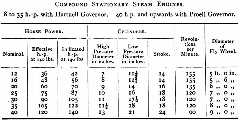
Very many of the engines and boilers on New Zealand dredges are from the works of Messrs. Marshall & Sons, Limited, Gainsborough, Lincolnshire, England, who make a specialty of steam plant for dredging purposes. The main engines are mostly
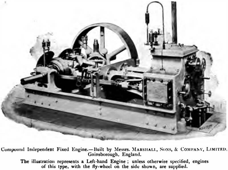
horizontal high-pressure compound, surface condensing. The illustration shows one of Messrs. Marshall & Sons’ independent compound type. These engines are of extra strength throughout, and are suitable for a working pressure of 140 lbs. per square inch. They are provided with Hartnell’s automatic expansion valve gear to the high-pressure cylinder; the cylinders are steam jacketted, an automatic sight feed lubricator is provided on the high-pressure cylinder, and a steam trap for draining the cylinder jackets. The crankshaft is of steel, of special length so as to leave room for pulleys for driving the dredge machinery, and balanced cranks and central bearing are included, as well as an outer bearing “ A ” standard beyond the flywheel, also a simple reversing gear.
As will be seen from the illustration, the entire engine is mounted on a steel frame, eminently suitable for dredges. A large number of these engines are at work on dredges in New Zealand, Australia, Siberia, North America, South America, Africa, Borneo— in fact, wherever gold dredging has been introduced, and they are giving out excellent results.
The following are particulars of the more usual engines supplied by Messrs. Marshall for dredges: —
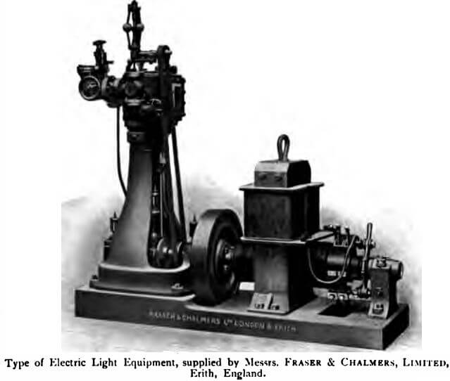
A substantial form of self-contained engine is made by Messrs. Fraser & Chalmers. The condenser air-pump is driven by an eccentric from the crankshaft, which is extended to take the driving pulley, and an outer bearing is supplied to withstand the heavy strains.
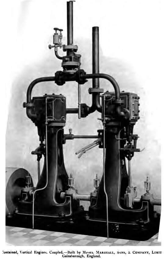
Independent engines, usually a pair of vertical coupled reversing engines, are provided for the winch. The usual type supplied by Messrs. Marshall’s is here illustrated. These engines are provided with link motion reversing gear, enabling the motion of the engines to be instantly reversed by means of a lever under the handy control of the driver, steam jacketted cylinders, specially long and strong steel crank-shaft with extra large bearings, one flywheel suitable for giving off the full power of both engines, and, if desired, the engines can be mounted on a cast-iron baseplate.
The Boiler
The Marshall boilers, specially designed for the purpose, are a combination of the Cornish and locomotive types, requiring no brickwork. The portions, circular throughout, are of two diameters, the larger of the two being at the furnace end, and diminished by curved plates to the smaller-diameter shell, the object being to reduce both the weight of the boiler and contained water, as well as to allow for the unequal expansion which comes on the Cornish type, when fired straight through, without returning the flue to the bottom. That portion of the shell which is largest in diameter carries the furnace, which terminates in a tubeplate; from this plate, a number of loco-boiler tubes pass through the smaller-diameter shell to another tube-plate at the smoke-box end. The smoke-box is filled with the usual door and a funnel about 25 ft. in height. This type of boiler is well suited for hard water and inferior rough wood fuel.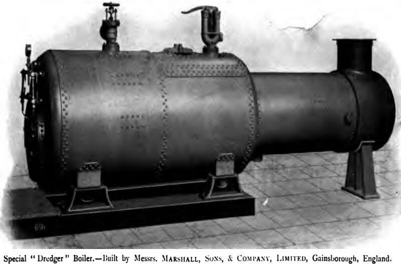
Messrs. Fraser & Chalmers manufacture two types of boilers for use on dredges. Both types are iron cased and self-contained. As will be seen from the illustration, the water-tube boiler occupies but small deck-room. The other type illustrated is a battery of underfired multi tubular boilers, so arranged as to be readily installed on a pontoon. To prevent stoppage of the dredge by failure of the water feed, the boilers are provided with a hand-pump in addition to injector and steam feed-pump.
Dredge Pumps
The Winch is compound, having at least six barrels or drums with clutches, friction brakes and levers, and is so arranged that the winchman, without moving more than a step or two, can work any one or more of the barrels in either direction. One barrel carries the galvanised wire rope, which, passing over the gantry and through a compound sheave, is used for raising or lowering the ladder; a second barrel is for the head mooring line, and the other four barrels are connected with the four side mooring lines. Many winches have a seventh barrel, which may be used for lifting heavy weights, or, in case of flood, for working a spare head line. The different makes of winches used are essentially of one type. In a dredge, built in Dunedin for work in Central Siberia, the winches have the usual four barrels for the side lines, a barrel for the ladder-lifting line, and two barrels for the head lines, one in case of emergency. But in addition to these seven barrels, there is a surging drum for odd purposes. Any one of the eight barrels can be used separately, or the whole eight can be worked at the same time by one man.
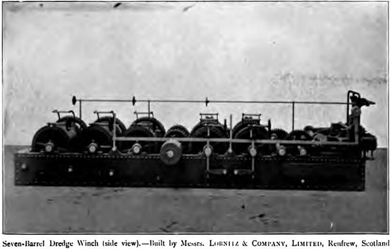
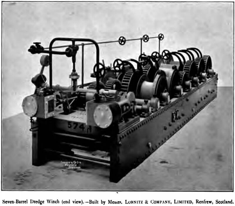
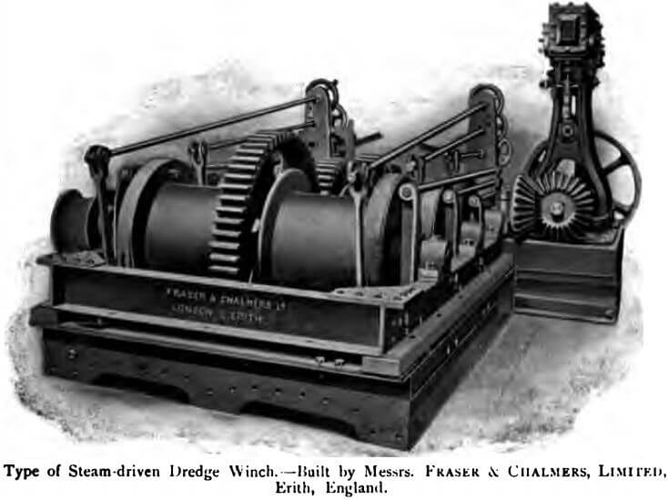
Winches should be very strongly constructed, with the gearing shrouded on both sides of the teeth, and with the barrels of ample diameter and size for the lines employed.
Bucket Ladders
Are usually built of angle iron and steel plates, less frequently of wood. In length they vary from 40 to 85 ft. It has been found that a ladder angle of 450 is most satisfactory for working the buckets; for when the wash is compact and requires to be torn out, the buckets should be well ahead of the pontoon. With loose wash, readily falling into the buckets, the inclination of the ladder may be much steeper. As in working it may be desirable to alter the angle, the more recent ladders are sometimes fitted with a telescopic arrangement by which the ladder can be lengthened or shortened some 3 or 4 ft.
The Buckets
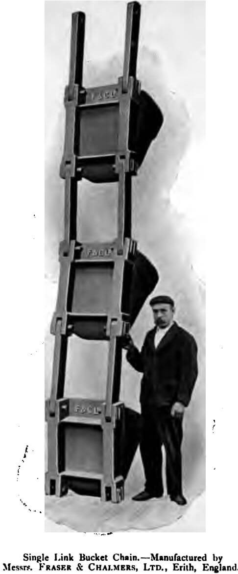
Buckets, which now vary from 3½ to 7 cubic ft. capacity, are built in various ways. In some cases the bottom or base is of the toughest, Swedish or Scotch, cast iron. Attached to this base are steel sides, fitted with a lip of the hardest steel. In other cases, they are built entirely of steel plate, and are rivetted on to usually one row on each side, of steel links, bushed with manganese steel, of which also the pins are made (see illustration, p. 34). Buckets of annealed Bessemer steel, with rim and wearing parts rivetted on, also are used.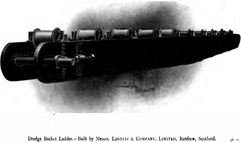
The shape and size of the buckets must be regulated by the class of wash to be treated. Those of rounded lips resist crushing better than flat lips, but they do not clear up the bottom so well. The buckets are provided with renewable lips of nickel steel or of manganese steel, but great care is required in making this latter, to insure uniform harness. Lips frequently crack transversely with little or no wear, causing loss of time and money in repairs. Size is not always desirable in buckets. In heavy wash small buckets will sometimes pay, where large buckets would eat up any surplus in repairs.
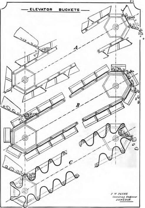
The patent elevator buckets of F. W. Payne, Dunedin, are said to work with less wear and tear and greater freedom from breakdown than the ordinary buckets.
The rate of discharge varies from 12 to 15 buckets per minute, for close, and from 18 to 28 for open-connected chains.
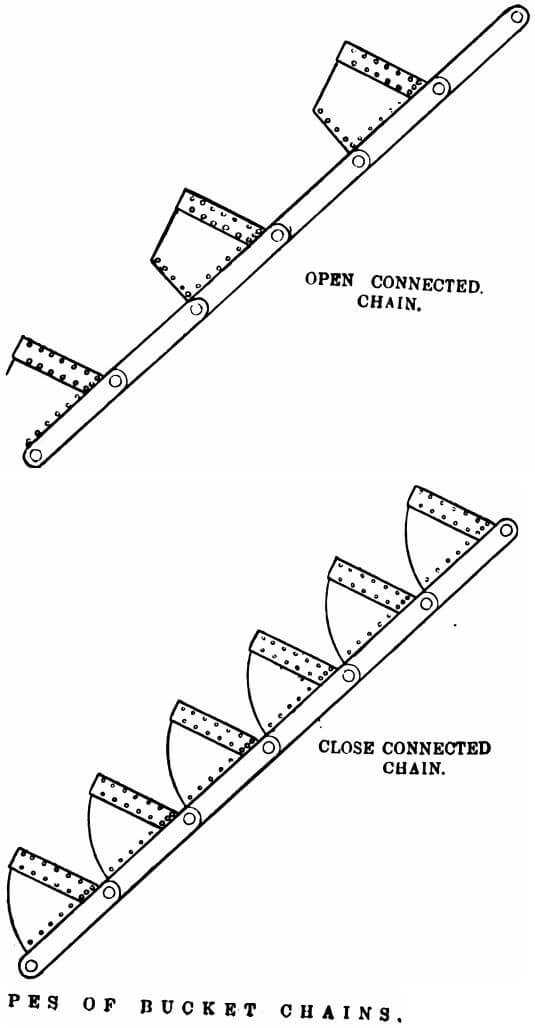
Buckets may be connected together, so as to form a chain, in two ways—with intervening links, forming “ open-connected chain”; by pins and bushes, without links, forming “ close-connected chain (see illustration, p. 35). For hard digging, Messrs. The Risdon Ironworks recommend open-connected buckets.
Dredge Grab Hooks
In addition to buckets, the chain is frequently provided with two or more pairs of grapnels, or grab-hooks. These hooks are of two kinds, the ordinary hook being much the same form as a bucket. The sketches will explain the difference between the two hooks, and the position of the pin-holes.
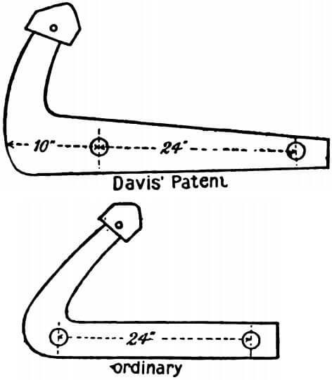
The construction of the Davis grapnel is such that on reaching the tumbler, the hooks project past the line of the bucket-lip and tear into tight gravels, thus acting as a pick. On leaving the tumbler they recede within the line of the lips. Grab-hooks serve not only to break down ground, but also to raise boulders too large for the buckets.
Transmission and Gearing.—The power is best transmitted from the engine to the machinery by belting or rope, which absorbs all shocks due to the unequal strains put upon the machinery by the
buckets dredging in rough ground. The centrifugal pump also is belt-driven. Owing to the enormous wear and tear, due to the attrition of the sand or stones, all wearing surfaces should be provided with hard metal or steel liners. Where possible, bearings should be rendered sand-proof by providing an annular groove, next to the stuffing- box, and supplying this groove with a jet of water under pressure, so as to exclude sand and grit. Ladder transmission gear is fitted with a friction device, for stopping the top tumbler revolving when the buckets catch or the chain breaks.
Mooring Lines, —These are usually wire cables, in number and size as follows: —
2 Stem side lines ………………………………….. 2 ins. in circumference.
2 Bow side lines ……………………………………….. 2½ ins. in circumference.
1 Head line ………………………………………………. 3½ ins. in circumference.
Besides these, there is the ladder line, for raising and lowering the ladder; this is about 3 ins. in circumference. These sizes vary according to size and design of dredge. They should be made of the best flexible steel wire. The lengths run about 50 to 60 fathoms for side lines, and 100 fathoms for the head line.
Lights.—For continuous work by night, powerful fore and aft and other other auxiliary lights are needed. For this purpose electricity, acetylene, and oil are all in use.
General Remarks.—As typical of New Zealand practice in dredge operations, Mr. C. E. Turner gives the following data: —
Bucket travel ……………………………………………… from 10 to 24 buckets per min.
Screen revolutions ……………………………………………… 12 to 20 per min.
Elevator trays …………………………………………….. 55 to 75 per min.
Pump revolutions ………………………………………………. about 600 per min.
Screen pitch ……………………………………………… from ¾ in. to 1¾ ins. per ft.
Screen table pitch ……………………………………………… 1¼ in. to 2 ins. per ft.
Outer tables ……………………………………………… 1 in. to 2 ins. per ft.
Angle of elevator from horizon 23°—30°