Table of Contents
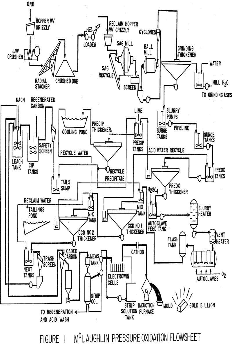
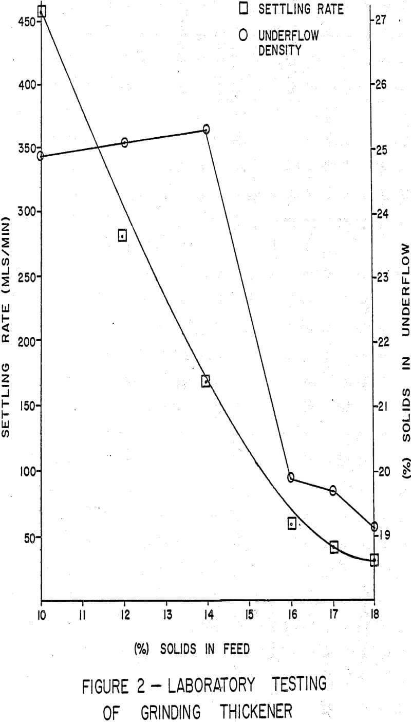
At start-up, the relatively high level of feed solids, 17-20%, called for in design led to difficulties in achieving the degree of flocculation necessary to meet required settling rates. It was recognized that decreasing feed solids would improve thickener performance while reducing flocculant consumption (Figure 2). This was accomplished by recycling thickener overflow to the feed launder and controlling feed solids at 10%.
Floccule Destruction
Too high slurry velocity in the feed launder caused the floccules being formed to be destroyed in the centerwell dropbox. The increased flow associated with the lower feed solids caused even greater turbulence in the launder compounding the problem of shearing floccules.
Shortly after startup, the slope of the feed launder was lessened and the center-well discharge box redesigned. A larger, deeper weired discharge box was installed. The intent of these changes being a reduction in turbulence through the box and in the centerwell by lowering inlet velocity and better dissipating flow energy. This in turn reduces the shear destruction of the forming floccules and reduces flocculant requirements. A “second generation dropbox” was installed in September 1987.
Flocculant Dilution
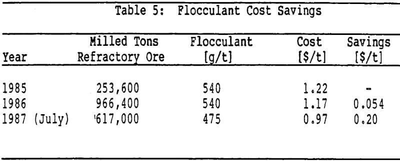
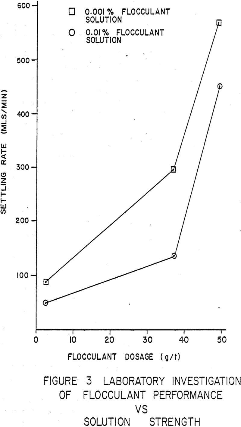
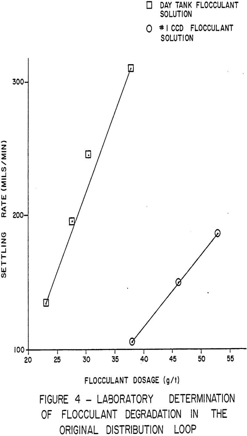
Replacement of the existing hydraulically limited gravity flow flocculant dilution system provided a significant decrease in flocculant consumption. Mill water returned to the launder for solids control was rerouted to the centerwell discharge box via a 150 mm (6 in.) pipeline. Stock flocculant solution is injected into the mill water line 18 m (60 ft) before the water discharges into the centerwell dropbox. This increased dilution showed an immediate and dramatic change in the solids settling rate and dosage requirement (Figure 3). Using massive dilution, greater than 100:1, results in near instantaneous flocculation of solids at the centerwell. An immediate reduction of 25 percent in flocculant dosage was seen.
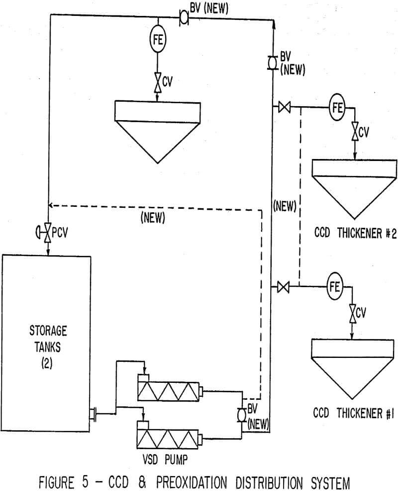
Flocculant dilution systems are being installed at both the preoxidation thickener and the CCD thickeners. Each system will provide a minimum 100:1 dilution to each thickener using its own overflow. A vertical centrifugal pump will deliver preoxidation thickener overflow from its sump back to the flocculant distribution header. Stock flocculant solution will be injected into the dilution line similar to the grinding system. The CCD dilution system will utilize the overhead solution advance lines to deliver dilution water directly to the distribution headers.
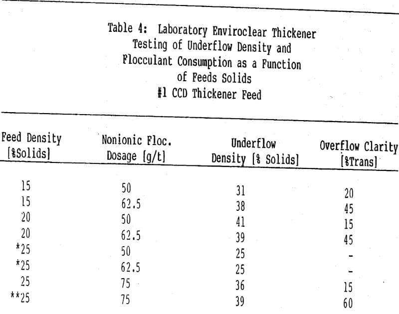
Feed Solids
Laboratory testing with a high rate thickener has shown the importance of feed solids control to thickener and flocculant performance (Table 4). In the preoxidation as well as CCD thickeners, testing has demonstrated that an optimum feed solids level can be attained which will maximize thickener performance while minimizing flocculant consumption. Above this optimum feed solids level, it is difficult to form discrete floccules as the slurry tends to gelatinize. Operating below the optimum level increases thickener upflow rate, which has a limiting effect on both underflow density and overflow clarity.