Table of Contents
A bewildering number of continuous thickeners and clarifiers are used in mineral industries and other heavy industries. General types are:
- Conventional Thickeners
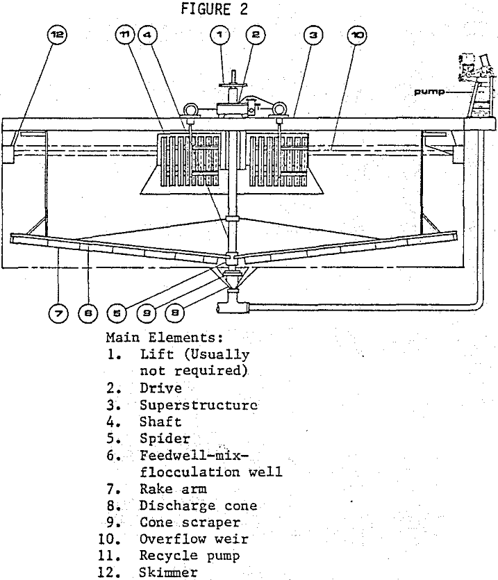
- Thickeners with Flocculating Feedwells
- Solids Contactors
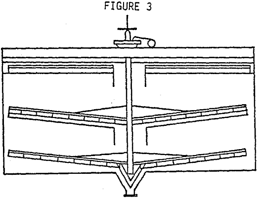
- Tray Thickeners
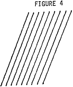
- Lamellas
- Conventional Thickeners with Lamellas
- High Flow, Fluid Bed Thickeners
These units must be adapted to varied applications. They must provide operating flexibility to meet process needs. Such factors multiply the decisions which must be made prior to the selection of a thickener.
Most thickener designs, suitable to minerals applications, are based on the separation of -65 mesh, 2.7 specific gravity solids containing slimes. These designs are routinely adapted to coarser and/or denser materials. Materials of lower specific gravity, such as coal, wood char, some chemical precipitates, and organics act like slimes if a thickener is applicable.
The problem then is to select hardware which will take into consideration the functions of flocculation, separation of the solids, water clarity, control of the underflow, and control of the overflow. Reliable operation and simple control are customary.
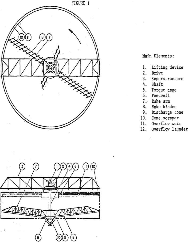
Feed Wells
An element which determines the effectiveness of all the following stages is the feed well. It controls and directs flow. In conventional thickeners, feed wells are cylindrical, and frequently baffled. In Lamellas and other types of thickeners, the feed wells can be an adjacent tank, a rectangular channel adjacent to the operating elements, a launder, a feed box, or an adjustable jet.
In the conventional thickener, particularly in the smaller units, the feed well is primarily a baffle to absorb energy. Usually it is a simple cylinder and can be roughly sized using a figure of 24 gpm/sq.ft. of area. This will approximate usual mill practice. This figure can vary between 15 and 70 gpm/sq.ft. according to the material being handled. If a particularly quiescent pool is required, a bigger feed well or more elaborate baffling is desirable. With fast settling materials, perhaps offering a rough separation, a small feed well, as compared to the volume of the feed stream, can be used. Where high rates are used, of course, baffling and careful feed direction is necessary. Usually the feed will be fed in tangentially to the walls of the feed well in order to permit the feed well to operate correctly as a baffle.
Control of flocculation is provided a number of ways. One way is to provide a feed well large enough to give the retention time necessary for flocculation. A second design proven effective is to provide a feed well that will give back-mixing and contact of the new floc with the old for the purposes of seeding and increased flocculation efficiency.
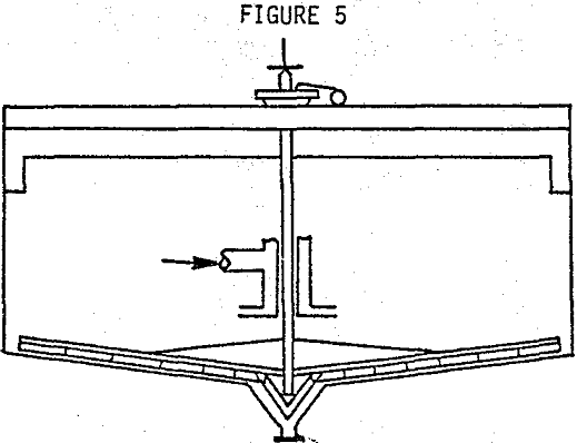
Rakes
Cones and Lamellas which have no rakes can only be used where the solids will not cement, set up, gel or bridge between plates. This problem has been partially solved with vibrators and by including Lamellas within conventional thickeners. There are also designs which permit fairly convenient cleaning of the plates.
Rakes are primarily designed to rake the sludge to the discharge well, usually in the center, where it can be pumped or drained away. In routine, day-to-day operation, this may be a minor function. Frequently the underflow will be a fluid mass that flows unaided. The rakes scrape the solids that may tend to accumulate on the bottom and also convey the solids in slurries when the underflow is thickened to a point where it no longer flows readily.
The speed of the rakes determines the raking capacity, minimizes turbulence where light flocs must be handled and aids flocculation. Coarse solids need and can tolerate higher rake speeds. Where flocculation is very effective, the rakes help when operating at relatively higher speeds.
Angle rakes, the most common kind, can be provided to rake once per revolution, twice per revolution, three times per revolution or four. These designs can make a substantial difference in raking capacity and also on cantilever forces due to uneven loading of the rakes on the drive shaft. In minerals applications raking two or four times per revolution is indicated.
The ability of rakes to respond to heavy applications is increased by a rake lift. Lifts that raise the rakes 2-3 feet from the bottom are common. Lifts add to the flexibility of a thickener operation by providing Storage of sludge, Emergency operation when sludge is too heavy for raking, and Ability to handle coarser or more heavily flocculated solids.
Tank Areas
Most of the literature, and perhaps most of the uncertainty in the selection of thickeners, is in the selection of the cross sectional area of the thickener. Most commonly, it is preferred that a sample be obtained and that the thickener be sized on the basis of test work. Pilot plant tests are complex but are often used. A reliable sample is not always available and, sometimes can not be generated from test work. In this case, the thickener must be sized from historical data and projected to the correct size mathematically.
The quick and very useful test usable in plant troubleshooting, estimates of thickener size, comparison of reagents and optimization of reagents, is the modified Kynch Method. The procedure, with curve, is included in a non-laboratory, editorial form. It illustrates the concept that area determines the capacity of thickeners.
The length of the Lamella plates can cause velocity problems since the sludge must settle a few inches from the separated water. The reduction in efficiency has caused interesting designs such as chevron type units with short plates and, in other cases, feed boxes beside the plates to minimize the difference in velocity due to differences in specific gravity.