Table of Contents
It is now generally admitted by experts that at least so far as rapid progress is concerned the Alpine system of tunnel-driving is superior to any other. This is perhaps natural in view of the record of experience in driving tunnels through the Alps. These great mountain-chains cannot be treated in the ordinary way by shaft-sinking and driving headings, thus multiplying the points of attack. The work must be done from the ends only, hence speed in driving is of the utmost importance ; and, as necessity is the mother of invention, the concentration of effort to make progress has resulted in an organization and in mechanical appliances that have produced results so much in excess of the usual practice, even in America, that a discussion of the subject in detail should be of much value to the engineer and contractor.
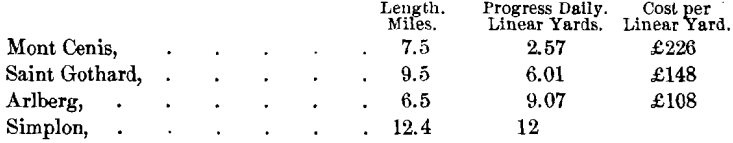
The first Alpine tunnel was the Mont Cenis, length 7.5 miles, driven with a progress that averaged about 7.75 ft. per day. Next came the Saint Gothard, 9.5 miles long, 18 ft. per day; Arlberg, 6.5 miles long, 27.25 ft. per day; Simplon, 12.25 miles long, 36 ft. per day.
The figures represent progress when driving from two headings, so that by dividing them in two we got the daily single-heading progress. The latest of the Alpine tunnels is the Loetschberg, now being driven. In this work the world’s record has been beaten by a single day’s record in one heading of 36 ft. and by an average daily record in one heading of 29.5 feet.
The Alpine range forms a natural barrier between a large section of northern and southern Europe. This range extends from the southeast of France to the frontier of Hungary, between Italy and the plains of southern Germany. The contour of the Alpine range is such that a traveler proceeding from Italy to France, Switzerland, or Germany, after traversing a comparatively easy pass over the main chain, may be brought abruptly against a second and loftier pass, or he may be compelled to follow a circuitous route which may double the length of the journey. The central portions of these mountains consist of gneiss, schists, granite, and other crystalline rocks. The range is an instructive example where a great mountain-chain has been formed by repeated movements during prolonged geological periods. Archibald Geikie, F.R.S., in describing the geology of this region, says :
“When the paroxysm of elevation had ended, one or more large lakes formed along the northern base of the mountains. In these hollows the Swiss molasse accumulated to a depth of more than 6,000 ft.—a great pile of slowly formed gravels, sands and clays. That the sea gained occasionally access to the region is shown by the interpolation of bands containing marine organisms. Not improbably a gradual subsidence of the region was going on during the formation of the molasse. But during the Miocene period another great epoch of mountain making was ushered in. The lakes disappeared, and their thick sediments were thrust up into large, broken, mountain masses. Since that great movement no paroxysm seems to have affected the Alpine region.”
Before surveys had been made of this mountain barrier the needs of war and commerce actuated people living on the opposite sides to seek the easiest and most direct route for crossing it, hence as far back as history records we find mention made of passes over the Alps. A pass is usually understood to be a depression between adjacent mountains, over which a trail is made. The Romans, beginning with Julius Caesar, became acquainted with the easiest and most serviceable passes of the Alps. It was always a difficult matter to cross over these passes, especially in winter, when storms and snow obstructed progress. To cross the Alps with an army, even in ancient times, without modern artillery, was a feat that compared favorably with winning a great battle. Hannibal, 200 years before Christ, crossed over the pass of Little Saint Bernard with an army of 20,000 infantry, 6,000 cavalry, and 37 elephants. This passage took 15 days and one-third of his army was lost en route. We have the authority of Livy for the statement that Hannibal, in order to widen some of the passages through the mountains, flaked off the material by heating the rocks and cooling them suddenly with liquids.
The credit for the modern revival of tunnel-construction on a large scale is due to Anne of Lusignan, who in the year 1450 gave it its first impulse by commencing the construction of a tunnel in the Alps, between Nice and Genoa, through the Col di Tenda (height of the pass, 1,800 m.). The work was stopped, but was subsequently continued by Victor Amadeus III. in 1782, finally being abandoned in 1794 in consequence of the invasion of the French; at this time about 2,500 m. of the tunnel is said to have been completed. While the tunnel projected under the Col di Tenda may be regarded as the modern revival of tunneling, there were equally ambitious projects carried out as early as the beginning of the Christian era, when, according to Pliny, the Emperor Claudius completed in A.D. 52 a tunnel from Lake Fucinus (Celano) to the river Liris. This tunnel undertaking is noteworthy as giving some information of the methods, labor, and tools employed in what was considered the greatest public work of the time. This was then by far the largest tunnel in the world, being 3.5 miles long, with a cross-section varying from 10 by 6 ft. to 20 by 9 ft. Forty shafts, some of which were 400 ft. deep, and a number of cuniculi, or inclined galleries, were sunk, and the excavated material was drawn up by windlasses, in copper pails of about 10 gal. capacity. It is reported that 30,000 laborers were employed 11 years in its completion. Where diorite, granite, and other hard stone had to be cut, the work was done by tube-drills and saws supplied with corundum or other hard, gritty material and water, the drills leaving a core of rock exactly like that of the modern core-drill.
“By referring to ancient writers—Pliny, Italiana Vitori, Lapidarium of Marbodus—we find that diamonds formed an important adjunct to the ‘ hewers of stone ’ as well as the lapidary. And it is thought by Eastern writers that diamond (shamer) pointed tools were used in the construction of Solomon’s temple, where ‘there was neither hammer, nor axe, nor any tool of iron heard in the house while it was in building.’ ”
Modern Alpine Tunnels
The era of tunnel-building in the Alps began with the Mont Cenis in 1857. The greatest of the Alpine tunnels, and the longest railway-tunnel in the world, is the Simplon, of which the Loetschberg, now under construction, is but an extension.
Since the opening of the Simplon tunnel, connecting Switzerland with Italy, the necessity of forming a route connecting it with the north and northeast of Europe has been apparent and has resulted in undertaking the construction of the Loetschberg tunnel through the Bernese Oberland. The general location of the Loetschberg tunnel and its rail-connections is, from the Simplon tunnel through the Loetschberg to Frutigen and Spiez on Lake Thun; from the entrance of the Simplon to the end of the Loetschberg may almost be considered as one tunnel-system.
A short review of the greater Swiss tunnels will illustrate the continual improvements in the construction-methods and plant employed, and an analysis of the methods of construction in these great tunnels indicates the cause which has led to the progressive increase in the economy and speed of tunnel-construction.
The advance of the heading or “ pilot ”—irrespective of whether it be driven top or bottom—is the factor controlling the rate of advance, as, under normal conditions, the enlargement to full size, timbering, and lining, readily keep pace with the advance of the heading. The manner of mucking in the headings and the time required to do it average about the same. The increased average gain in the rate of advance has been concurrent with the improvement in the machinery employed in the headings.
Where a great thickness of rock overlies a tunnel, it is necessary to do the work wholly from the two ends, without intermediate shafts. The problem resolves itself into devising the most expeditious way of excavating and removing the rock. Experience has led to great advances in speed and economy, as will be seen from the particulars of the tunnels through the Alps.
In 1857 the first blast was fired in connection with the Mont Cenis work; in 1861 machine-drilling was introduced; and in 1871 the tunnel was opened for traffic.
With the exception of about 300 yd., the tunnel is lined throughout with brick or stone. Little interest now attaches to the method of tunneling adopted at Mont Cenis, as it is, in several respects, obsolete. During the first four years of hand- labor the average progress was not more than 9 in. per day on each side of the Alps, but with compressed-air rock-drills the rate towards the end was five times greater.
In 1872 the Saint Gothard tunnel was commenced, and in 1881 the first locomotive ran through it. Mechanical drills were used from the commencement.
Tunneling was carried on by driving in advance a top-heading about 8 ft. sq., then enlarging this sideways, and finally sinking the excavation to invert-level. Air for working the rock-drills was compressed to 7 atmospheres by turbines of about 2,000 h.p. From 6 to 8 Ferroux drills, making about 180 blows per min., were mounted on a carriage pushed to the point of attack. From 13 to 18 holes were drilled by the machine and its 16 attendants to depths of from 2 ft. 7 in. to 4 ft. 3 in. in from 3 to 5 hr., and the work of charging with dynamite, firing, and clearing away was then done by 22 men in from 3 to 4 hr. The charge per hole averaged 1.75 lb., and after firing, a strong current of compressed air was directed over the face of the excavation. Four sets of holes were, under favorable circumstances, drilled in 24 hr., which rendered attainable, in each heading, a progress of 13 ft. a day in such rock as gneiss.
The driving of the Arlberg tunnel was commenced in 1880, and the work completed in little more than three years. The main heading was driven along the bottom of the tunnel and shafts were opened up from 25 to 70 yd. apart, from which smaller headings were driven right and left. The tunnel was enlarged to its full section at different points simultaneously in lengths of 8 yd., the excavation of each requiring about 20 days, and the masonry 14 days. Ferroux percussion air-drills and Brandt rotary hydraulic drills were used, and the performance of the latter was especially satisfactory. After each blast a fine spray of water was injected, which assisted the ventilation materially. In the Saint Gothard tunnel the discharge of the air-drills was relied on for ventilation. In the Arlberg tunnel more than 8,000 cu. ft. of air per min. was thrown in by ventilators. In long tunnels the quick transport of materials is of equal importance with rapid drilling and blasting. In the Arlberg, to keep pace with the miners, 900 tons of excavated material had to be removed, and 350 tons of masonry to be introduced, daily, at each end of the tunnels, which necessitated the passage of 450 cars. This traffic was carried on over a length of 3.5 miles on a single track of 27-in. gauge with two sidings. When the locomotives ran into the tunnel the fires were damped down, and as the pressure in the boiler was 15 atmospheres, the stored-up heat in the water furnished the necessary power. The cost per linear yard varied according to the thickness of masonry lining and the distance from the mouth of the tunnel. For the first 100 yd. from the entrance the prices per linear yard were £11 8s. for the lower heading; £7 12s. for the upper one; £30 10s. for the unlined tunnel; £45 for the tunnel with a thin lining of masonry; and £124 5s. with a lining 3 ft. thick at the arch, 4 ft. at the sides, and 2 ft. 8 in. at the invert.
The Simplon Tunnel
In 1893 the Jura-Simplon Railway Co. contracted with Brandt, Brandau & Co., of Winterthur, Switzerland, for the construction of a tunnel from Brigue, on the north side, to Iselle, on the Italian side of the Simplon pass, and 12.4 miles in length. The contract time for construction was 5.5 years.
It is but natural that in this Alpine region, where water is available, the engineers should have planned to make use of this power not only for the purpose of compressing air, hut for hoists, and even for use in rock-drill cylinders. Water-power was employed for all purposes at each end of the tunnel. The Simplon tunnel runs upgrade from each end towards its center, hence there is a natural drainage, which saves pumping. Engineers, who, without visiting the Simplon during construction, learned of the great progress made there by the hydraulic process, were inclined to adopt the same methods in work less favorably situated. It is one thing to use the hydraulic system where there is a natural race-way taking care of the discharge of the water, and it is quite another thing to expend the power required to pump this water. At the time the East River tunnels, in New York City, were built by S. Pearson & Son for the Pennsylvania railroad, serious consideration was given to the hydraulic process, because, as is well known to those familiar with conditions about New York, tunneling under the East river involves rock-work, while Hudson river tunneling is entirely through mud. Mr. Moir, who had charge of the East river tunnels, was impressed by the great progress which had been made at Simplon, where hydraulic machinery was used, but, upon investigation, decided that there was no advantage to be gained by using a system, which involved lifting the water which had been used for power purposes; hence these East river tunnels were equipped exclusively with compressed- air machinery.
Power
At the Swiss end the river Rhone was dammed, the water collected in reservoirs provided with gates, and carried for about 2 miles in a reinforced-concrete flume to the power-house. The power available here was about 2,200 horse-power.
At the Italian end the power was derived from the Diveria, about 2.5 miles above the works. The power-house contained three Pelton wheels, two of 250 h-p. each, and one of 600 h-p.; the wheels were horizontal and ran at 170 rev. per min. The pressure-pumps were operated by these wheels; the highest pressure available at these pumps was about 120 atmospheres per sq. cm., with a capacity of about 65 gal. per min. at a pressure of 1,175 lb. per sq. in. In the pump-room were also two air-compressors of Ingersoll and Buckhardt types. At the Italian end there was also a supplementary steam-power plant of about 220 horse-power.
The distribution of the power was proportioned about as follows: for high-pressure pumps, 700; for air-compressors, 400 ; for ventilation, 500; for illumination, 100 ; for machines in the shops, 100; making a total of 1,800 horse-power.
Ventilation
For ventilating the tunnel during construction and afterwards, a permanent plant was installed at each end, the power being taken from the 200-h-p. turbines, at each plant, running at 400 rev. per min., and driving two fans of 12.3 ft. diameter. The air-passages from the ventilator-house bifurcate near the tunnel ends. A door at the angle of the bifurcation permits the closing of either fork of the passage; sail-cloth curtains close the tunnel portals. Air could thus be circulated in either tunnel as desired, its movement being controlled either by compression or by aspiration.
Rock-Temperature
The highest temperature encountered during construction was 55° C., and was encountered during 1902, about 8 km. from the Swiss end. The method of refrigerating the air in the workings was the same at each end; cold water was forced into the headings and there broken into spray.
Illumination
For illumination at the north end gas was used; at the south end each miner carried an oil-lamp.
Drainage
The drainage of the tunnel was effected by gravity, except for about 500 m. in the center of the tunnel.
Transportation
The transportation-service was one of the most important portions of the tunnel-work. The motive-power used consisted at both ends of steam-locomotives, compressed-air locomotives, and horses. The steam-locomotives worked up to about 1,500 ft., and from this point the air-locomotives worked to within about 1,000 ft. of the headings; the remaining haul being done with horses.
Method of Construction
The distance between portals is 12.4 miles, and except for a short curve at each end, the alignment is straight. The elevation of the Swiss portal is 2,250 ft. and of the Italian portal 2,076 ft. above sea-level; the highest point in the tunnel is midway between the portals, and is at an elevation of 2,310 ft.; from this summit-level the line descends on a 2-per cent, grade to Brigue, and on a 7-per cent, grade to Iselle on the Italian end.
The work consists of twin single-track tunnels exactly parallel in plan and profile, and lined throughout with masonry. The centers of the tunnels are 55.76 ft. apart; at the summit-level the cross-section is increased in dimensions to accommodate two tracks.
A center bottom drift was first driven by power-drills, and then timbered and covered with a closely-boarded roof. From this drift a shaft was driven upward to the roof-line every 164 ft. (50 m.). The top heading was then excavated by working in both directions from each of these shafts. Next in order, the floor of the upper heading was removed and then the two side cheeks of the bottom drift. The lower drift being timbered, no interruption of the traffic in it was caused by the removal of the rock above.
Drilling
The advance drift was the only part of the operation performed by power-drills. The drills employed were Brandt rotary machines mounted in groups of two on a heavy thrust-bar about 12 in. in diameter. This thrust-bar was pivoted to a drill-carriage and was counter-balanced.
The section at the heading was nominally 6.5 by 9.5 ft., or 61.75 sq. ft., and as the depth of each blast was roughly 4.5 ft, the material removed by each blast ranged from 265 to 275 cubic feet.
The average daily advance was about 16 ft. at the Italian end and from 20 to 21 ft. at the Swiss end. This work was in gneiss rock. In rock of more friable nature, such as anhydrite or calcium sulphate, an advance of as much as 34 ft. in 24 hr. was made. After each blast, the time required to clean the heading, set the drills, complete the boring, and remove the drill-carriage, was more than an hour.
Explosives
The explosives used were dynamite at the Italian end, and blasting-gelatine at the Swiss end.
The dynamite was put up in packages of about 1 lb. in weight; each hole was charged with six cartridges; each blast in the drift, therefore, used from 60 to 66 lb. of powder, or about 6.5 lb. to the cubic yard. Charges were fired by ordinary fuses, cut so as to give an interval between the firing of successive holes; about 15 min. was required after each blast to clear the fumes from the heading. This was accomplished by means of a ventilating-pipe running close to the face and the use of a spray of water. The ventilating-pipe exhausted about 35 cu. ft. of air per sec., and the spray absorbed the gases.
Mucking
The spoil was cleared from the face by one gang while another gang loaded the collected muck into narrow-gauge cars hauled by horses. No machines were used, all the material being handled by manual labor. The work of clearing the heading was rushed to enable the drills to be put to work as soon as possible. To this end the clearing-gangs were composed of men who had been previously rested by performing light work only, and only the most skilled and energetic laborers were employed. The majority of the workers were from southern Italy. There were 14 or 15 men at each heading, worked in three shifts daily. Each gang had two horses for each shift. Horses, which cost $1.60 per 8-hr. shift, died off rapidly and were paid for by the tunnel-contractors. Other methods of transportation were tried but proved less economical than the use of horses in the advance headings. The horses took the cars to the compressed-air locomotives, and these in turn took them to the steam-locomotives, as already described.
Geological Conditions
The materials penetrated, beginning at the working entrance at the Italian end, are as follows : At the entrance a crust of quartz; following this for 14,268 ft. was a very hard gneiss lying in horizontal strata and known as antigoria; the gneiss contained occasional seams of crystalline rock, quartz, sulphur, pyrites, etc. Beyond for a distance of about 130 ft. a disintegrated slate clay was encountered, which proved a most treacherous material and was the most difficult part of the tunnel. Succeeding the disintegrated slate for about 200 ft. was a mixture of mica-schist, schistic gneiss, cipolin, quartz, and white marble, followed by about 325 ft. of anhydrite or crystalline calcium sulphate; then followed calcareous rock, schists, anhydrite, granitoid rock, and schistic gneiss, the last being nearly as dense and hard as the antigoria first encountered. All these formations were in horizontal strata.
To pass the disintegrated clay and slate a method of steel- and-timber strutting was employed.
In antigoric gneiss the time taken for each portion of the attack was as follows:
Bringing up and adjusting drills,…………………………..20 min.
Drilling,…………………………………………….1 hr. 45 min., to 2 hr. 30 min.
Charging and firing,……………………………………….15 min.
Clearing away debris,………………………………….2 hr.
or for one whole attack, between 4.5 and 5.5 hr., resulting in an advance of 3 ft. 9 in., or a daily advance of 18 feet.
From this it appears that the time spent in clearing away the spoil equaled that consumed in drilling, and it is in this clearing that a saving of time is likely to be effected rather than in the process of drilling.
The average temperature at the face was 73° F. during drilling-operations, 76° F. after firing, and a maximum of 80° F. on the south side, with 80° F. and 85° F. before and after firing.
Rate of Progress
The progress for three months is given in the trial-report for 1900 as follows:
At Brique, where there were three drilling-machines in one heading and two in the parallel heading, the total length excavated was 995 yd., or 6,409 cu. yd., in 89 working days. The average cross-sectional area was 57 sq. ft. This required 507 attacks and 3,066 holes, which had a total depth of 26,600 ft., and 14,700 re-sharpenings of the drilling-tool.
At Brigue 648 men and 29 horses were employed at one time in the tunnel. At Iselle the numbers were 496 men and 16 horses, working in shifts of 8 hr. Outside the tunnel in the shops, forges, etc., the men work 8 to 11 hr. per day, the total being 541 men at Brigue and 346 men at Iselle.
On the Italian side, where the rock is very much harder, there were three drilling-machines in each heading, the total length excavated, with a cross-sectional area of 62 sq. ft., was 960 yd., or 6,700 cu. yd., in 91 working days. This required 61,293 re-sharpened tools, 758 attacks, 7,940 holes, with a total depth of 33,000 ft., and 56,000 lb. of dynamite. The average time spent in drilling was 2 hr. and 55 min., and in charging and clearing, 2 hr. 36 min.
Thus in the hard gneiss, to excavate 1 cu. yd. of rock required 8.5 lb. of dynamite and each tool pierced 6.5 in. of rock before it required resharpening.
The Loetschberg tunnel
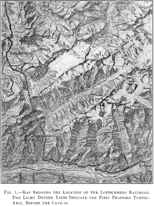
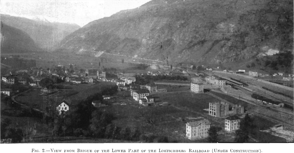
The Loetschberg tunnel, driven through the Bernese Alps, in Switzerland, is the last link of a railroad system connecting the city of Berne directly with the village of Brigue, which is situated at the north portal of the Simplon tunnel. With its completion, and the lately finished 12,000-ft. Weisenstein rail-road-tunnel located about 80 miles north of Berne, it forms the shortest route between London, Paris, Brussels, or Hamburg, and Genoa, via Berne, Thun, Brigue, and Milan. A sketch-map of the Loetschberg railroad is given in Fig. 1, and a view from Brigue of the lower part of the road, under construction, is presented in Fig. 2.
The question of connecting the Bernese Oberland with the Rhone valley had its origin as far back as the year 1866, and the present location of the tunnel was proposed in 1899. In that year two consulting engineers, at the request of the Bernese government, began a careful study of the location of the proposed road, and reported in favor of a single-track tunnel 44,500 ft. long, basing their estimate on an average cost of $4.90 per cu. yd. for tunnel-excavation and $6.55 per cu. yd. for masonry lining throughout the tunnel-length. The total cost of the tunnel was estimated at $107 per linear foot.
Assuming an average progress of 4 ft. per day for hand-drilling, or from 5 to 8 ft. for machine-drilling, and from 15 to 18 ft. for rapid driving, the time required for driving the tunnel was estimated at 5 years. The maximum rock-temperature expected to be encountered was 95° F.
Later on, however, the expected increase of the traffic through the Simplon tunnel brought out the question of accommodating two tracks in the proposed tunnel, and therefore it was decided to drive a double-track tunnel.
Estimates were prepared, and the cost of the new proposed tunnel was calculated to be :
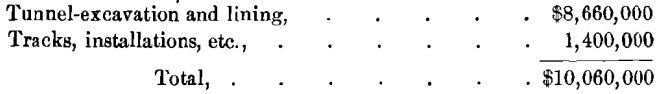
or a total cost of $211 per linear foot.
The franchise for building the road was granted to the Canton Berne in December, 1899, and, aside from 6,000,000 francs furnished by that canton, the necessary capital for building the road was obtained from French bankers.
The main offices of the company, Die Berner Alpenbahn Gesellschaft, are situated in Berne, while the main office of the contracting company is in Paris. A. Zollinger is the chief engineer.
The chief engineer for the company on the north portal is Mr. Von Erlach, and for the contractor Mr. Rothpletz; while for the south side Mr. Imhof is chief engineer for the company and Mr. Moreau for the contractor.
The new road begins at Frutigen, in the Bernese Oberland, about 82.5 miles from the north portal; 50.5 per cent, of this length is on horizontal curves, and 90 per cent, is on grade. There are 12 tunnels, aggregating 16,000 ft., one of which is a spiral tunnel 5,460 ft. long, with a 985-ft. radius. The maximum grade is 2.7 per cent., and the difference in elevation between Frutigen and the north portal of the Loetschberg tunnel is 1,370 feet.
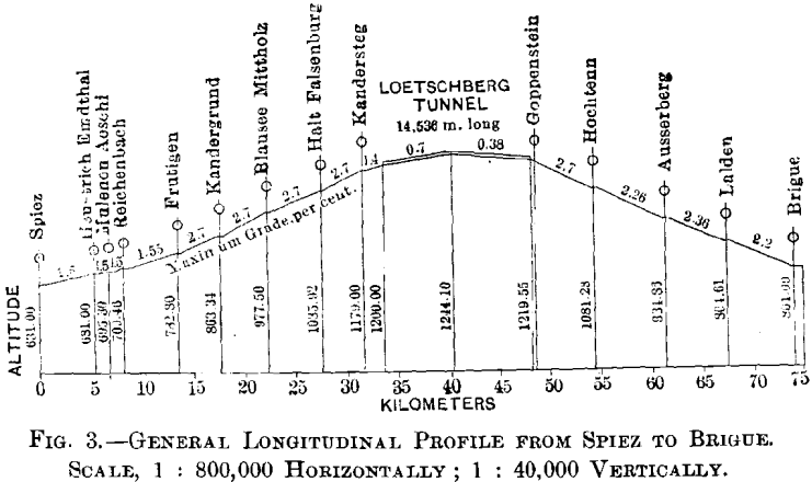
The main tunnel is 47,678 ft. long, and was first planned to be on a tangent. After the cave-in of July 24, 1908, it was found necessary to insert a curve of 3,600 ft. radius in the tunnel in order to drive through solid rock. The elevation of the north portal is 3,940 ft.; of the south portal is 4,000 ft., and the maximum elevation of the tunnel is 4,081 ft. above sea-level. The maximum grade in the tunnel is 7 per cent. The distance from the south portal to the end of the line, at Brigue, is 15.75 miles. Of this length 28 per cent., or 23,200 ft., consists of 21 tunnels, the longest being 4,450 ft. Of this stretch 54 per cent, is on curves, and 90 per cent, on grade. The difference in elevation between the south portal and Brigue is 1,110 ft., and the maximum grade is 2.7 per cent. The general profile from Spiez to Brigue is shown in Fig. 3.
Summarizing, the total length of the road is 45.8 miles, of which 36 per cent., or 86,900 ft., is tunnels. Let it be added that, for construction purposes, a narrow-gauge railway had first to be built to reach both portals. On the south side
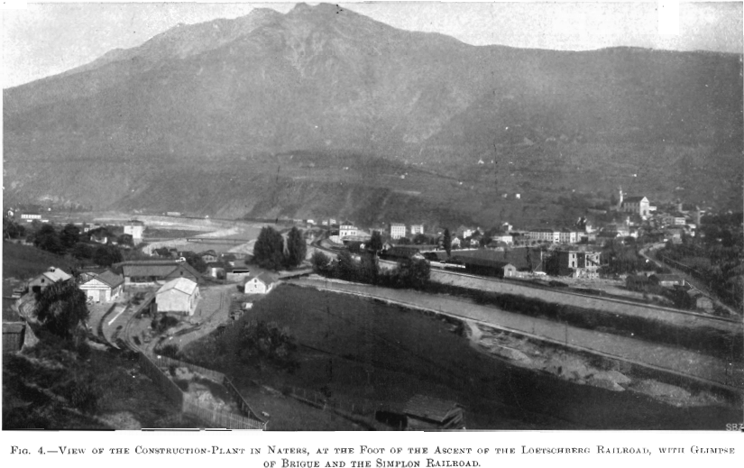
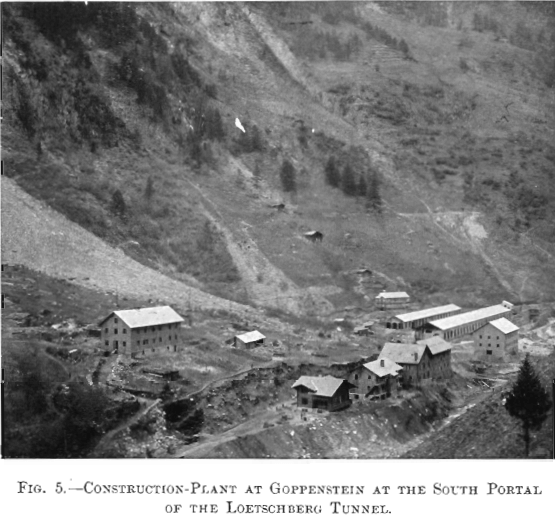
of the tunnel the construction-railway necessitated 38 tunnels, aggregating 18,000 ft. Of the 38 tunnels, 11 only will be part of the permanent road. A view of the construction-plant at Haters at the foot of the Loetschberg railroad, giving a glimpse of Brigue and the Simplon railroad, is given in Fig. 4, and that at Goppenstein, at the south portal of the tunnel, in Fig. 5.
Geological Conditions
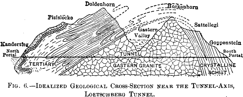
Beginning at the north portal, the materials penetrated have been calcareous for a distance of about 13,100 ft.; while on the south side, crystalline schist has been found on about 13,000 ft., and granite, forming the central part of the mountain, has been penetrated by both headings. Fig. 6 is an idealized section near the tunnel-axis.
But little water was encountered in the south heading, about 20 gal. per sec.; while in the north heading, 105 gal. per sec. necessitated the construction of quite a large-sized drainage-ditch.
On July 24, 1908, when the main heading had reached a point 1.6 miles from the portal, it struck a cleft filled with sand, gravel, and water. There was a sudden and violent inburst of these materials, which in a few moments filled up the tunnel for a length of 5,900 ft., burying 25 workmen and all the drills and other installations beyond hope of recovery. It is estimated that about 8,000 cu. yd. of sand and gravel entered the tunnel.
To avoid any further irruption of the materials, the tunnel was walled up by a 33-ft. wall at a point 4,675 ft. from the portal.
A commission of engineers was convened to decide upon a course to be adopted. Three methods were considered: (1) To force the tunnel through on the original line; this was considered impracticable, due to the great pressure from the 590 ft. depth of water, sand, and gravel over the tunnel. (2) To use the freezing-process; this also was considered impracticable. (3) To deviate the line and cross the Gastern valley further up stream. The last plan was adopted, and is shown in Fig. 1. The new line leaves the original location at a point 0.75 mile from the north portal. No further serious difficulty was experienced in tunneling through the diversion.
Rock-Temperature
The usual high rock-temperature met during the construction of the Simplon tunnel was a serious hindrance to rapid driving. Careful studies were therefore made in order to determine the maximum temperature to be expected in driving the Loetschberg tunnel.
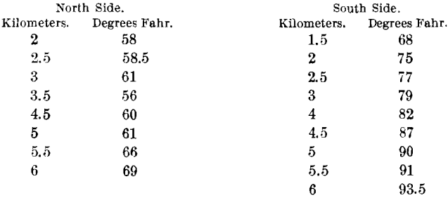
As above stated, preliminary studies had fixed this maximum rock-temperature at 95° F. It was expected that this temperature might be slightly exceeded, and due provision was made for taking care of it. With 86 per cent, of tunnel completed the maximum rock-temperature recorded has been 91° F., and it is not expected that this figure will be very much exceeded.
The following rock-temperatures have been observed.
Rate of Progress
Driving of the headings was begun on Oct. 1, 1906, for a single-track tunnel, and continued until Oct. 1, 1907, when it was decided to drive a double-track tunnel; 86 per cent, of the tunnel had been driven by Oct. 31, 1910. The headings met Mar. 31, 1911. On Oct. 31, 1910, the 4,000 ft. of heading which had been abandoned after the cave-in of 1908 had been regained.
Power
The power-plant for the south heading is situated at Goppenstein. It is driven by electric power. The current is brought at 15,000 volts, and stepped down to 500 volts for power-purposes.
Compressed air for the drills (Ingersoll-Rand) is furnished by 3 two-stage Ingersoll-Rand compressors, each having a capacity of 1,950 cu. ft. of free air per min., and a compression of 145 lb. per sq. in. They are driven by 400-h-p. electric motors. Compressed air for the locomotives is furnished by 2 four-stage Ingersoll-Rand compressors, having a capacity of 460 cu. ft. of free air per min., and a compression of 1,760 lb. per sq. in. They are driven by 250-h-p. electric motors.
The power-plant for the north heading is situated in Kandersteg. Electric power, used throughout the works, is brought
from Spiez at 15,000 volts, and stepped down to 500 volts for power-purposes in the tunnel as well as in the shops.
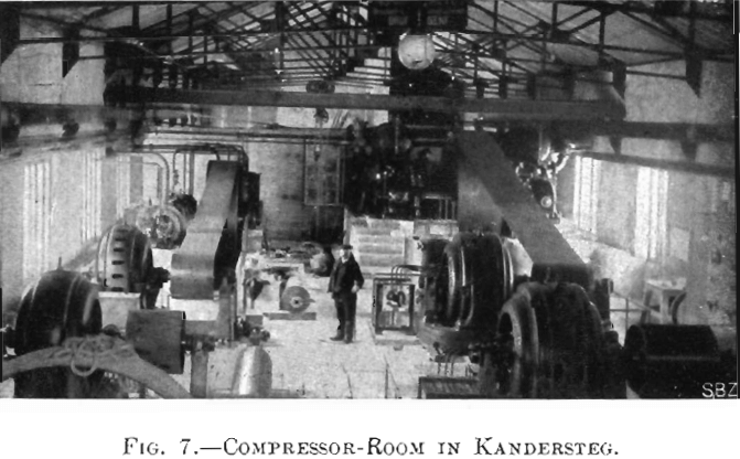
Compressed air for the drills (Meyer) is furnished by two units, each consisting of a two-stage Meyer air-compressor, each having a capacity of 1,770 cu. ft. of free air per min., and a pressure of 117 lb. per sq. in. They are belt-driven by 450-h-p. electric motors. A view of the compressor-room at Kandersteg is given in Fig. 7.
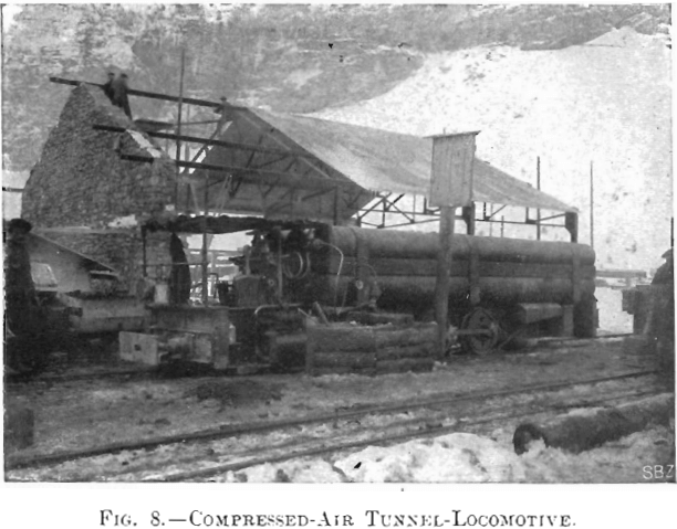
Compressed air for the locomotives is furnished by two units, each consisting of a five-stage Meyer high-pressure compressor, with a capacity of 565 cu. ft. of free air per min., and a pressure of 1,760 lb. per sq. in. They are belt-driven by a 250-h-p. electric motor. Fig. 8 is a view of a compressed-air locomotive.
Transportation
All trains in the tunnel are operated on a regular time-schedule, changed from time to time according to the progress of driving.
Steam-locomotives are used outside, while compressed-air locomotives are run inside of the tunnel. A few mules are still in use in the south bottom-heading.
Four types of cars are used for the service inside and outside of the tunnel: (1) Passenger-cars having a capacity of 24 men each, and run only when shifts are leaving or entering the tunnel. (2) Cars having a capacity of 85 cu. ft., used for mucking. (3) Cars of 70 cu. ft. capacity, used chiefly for transporting masonry. (4) Flat cars, used for bringing in timber, rails, etc. The cars used for mucking are 6 ft long, 2 ft. 8 in. wide, and 2 ft. deep, the upper edge being 3 ft. 7 in. above the top of the rail.
The gauge for all tracks laid in the tunnel is 30 in.; the rails, of from 30 to 40 lb. per yd., being laid on wooden stringers, except in the last 100 ft. of the bottom heading, where portable rails with pressed-steel ties are used. Trains are run in the tunnel at a speed of from 8 to 10 miles per hour.
Lighting
Electric light is used only in that part of the tunnel already lined with masonry and partly completed.
Portable acetylene-lamps are used throughout the tunnel with a few exceptions only. They are sold to the men by the contractors for the sum of $1. Besides giving a very bright light, these lamps are clean, easily handled, and they do not give out fumes as do oil-lamps.
Drainage
Drainage on the north side of the tunnel is provided by means of a ditch 2 ft. 8 in. wide, and 2 ft. deep, placed between the two tracks. It has the same slope as the tunnel. The flow of all springs encountered on this side of the tunnel amounts to about 105 gal. per sec., most of the water coming from that part of the tunnel where the cave-in occurred in 1908. The flow on the south side of the tunnel amounting to only 20 gal. per sec., the section of the drainage-ditch is but half the size of the one above named.
The Drill-Carriage
The records made in driving the headings are due to the excellent organization, and to the methods of setting up and taking down the drills.
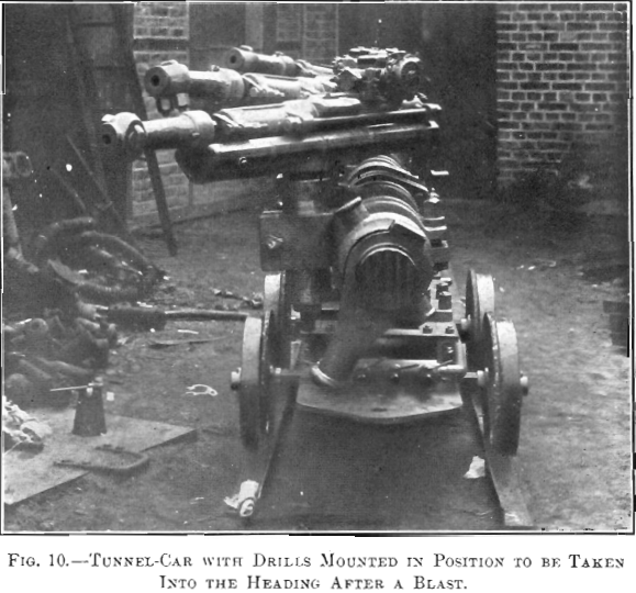
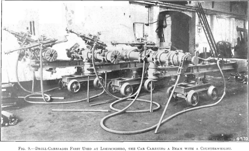
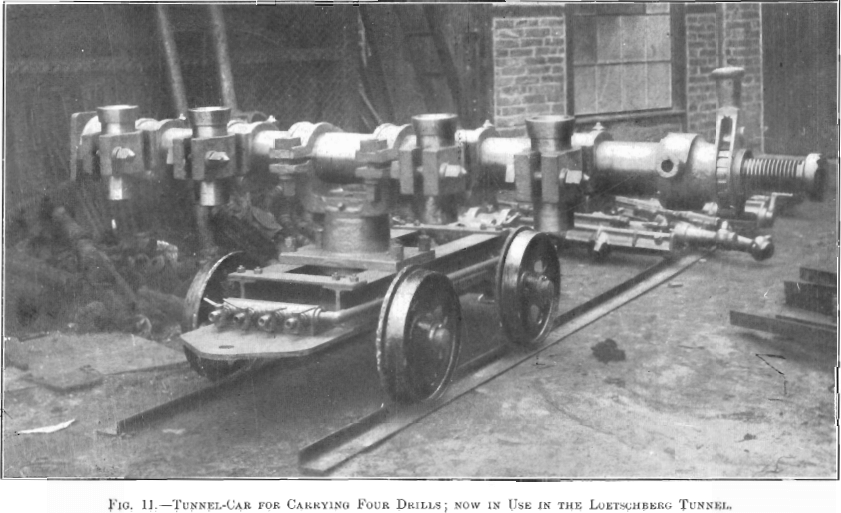
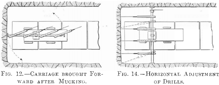
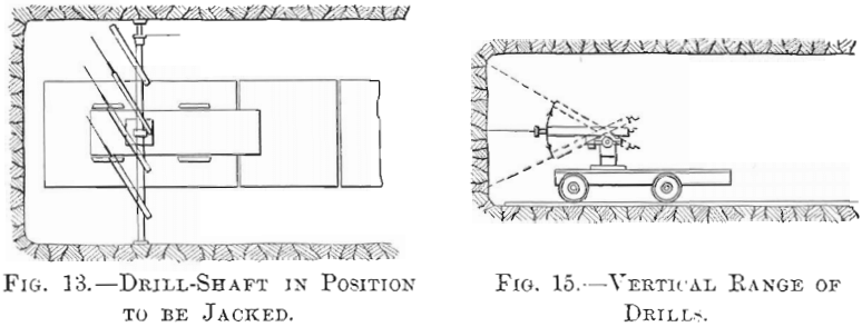
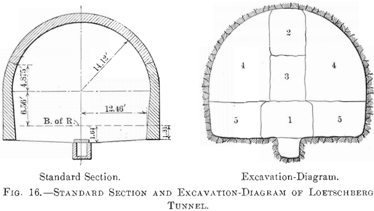
Fig. 9 shows the type of drill-carriage first used at Loetschberg, carrying a beam with a counterweight. Fig. 10 is a view of a carriage with drills mounted in position to be taken into the heading after a blast, and Fig. 11, the carriage carrying four drills now in use at the Loetschberg tunnel. In this type the beam and counterweight are omitted, the bar, on which four, five, or six drills are mounted, being placed directly on the truck. The width of the tunnel in which these cars can operate varies from 6 to 13 feet.
A drill-carriage of simple but efficient design was devised by the contractors. Each carriage carries four or five drills. Fig. 12 shows the carriage, together with the drilling-machines, when brought forward just after mucking in the heading. Fig. 13 shows the horizontal shaft swung into position ready for being jacked, and the drills ready to be swung into the position shown in Fig. 14. It can be easily seen from Fig. 14 that the drills can be independently swung through an arc of a circle or moved sideways, while in Fig. 15 the different positions which the drills can be given by being swung in a vertical plane are shown.
The time required to change the machine from the position shown in Fig. 12 to that shown in Fig. 14 and to commence drilling is usually from 6 to 8 min. This fact alone shows the superiority of this system of carrying the drills for such work over any other method used up to the present time.
Explosives
Three kinds of explosives are used. Dynamite, with about 85 per cent, of nitro-glycerine, is mostly used in the headings. Westphalite and cheddite, being more safely handled, are used for enlarging and for small blasts.
Great stress is laid on the fact that a high-grade explosive breaks the rock into small pieces, not larger than an orange, which enables mucking to be done with shovels.
Firing is done with ordinary fuses. The dynamite cartridges are wrapped with red paper in order to be easily detected in case of a mis-fire. Dynamite-carriers and handlers are provided with red lanterns.
Excavation
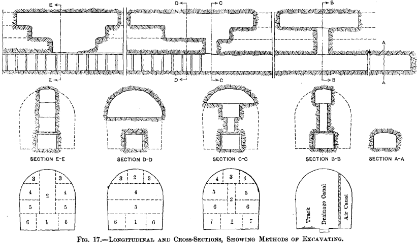
As shown in Fig. 16, the width of the finished tunnel-section is 28 ft. at the arch-springing and 25 ft. at the base of the rail. The arch is semi-circular, the crown being 20.7 ft. above the base of rail.
The sequence of excavation is illustrated by Fig. 17. A bottom heading 6.5 by 10 ft. is first driven several hundred feet in advance of the enlargement. Upraises are then driven from 500 to 600 ft. apart, and a top heading started back and forth. The top heading is then enlarged as shown by the sections in Fig. 17.
When the inclination of the strata is vertical or the formation is of a treacherous nature, the method illustrated by Sections B-B and E-E in Fig. 17 is used.
In the bottom heading the mining-operations proceed as follows: The drill-carriage is run forward from its siding close to the face of the heading, passing over 5 ft. by 5 ft. by 3/8-in. steel plates laid on the floor of the heading for a length of about 30 ft. Each plate is provided with 1-in. holes at the corners for ease in handling with a pick.
The water- and air-pipes laid on one side of the heading to about 40 ft. from its face are connected with the drill-carriage, and the drilling begins with the top holes. Water-sprinkling is frequently done, especially in starting the holes, in order to lay the dust.
Without interfering with drilling, mucking is going on just behind the drill-carriage, and the loaded muck-cars are run back to a siding, where trains of from 20 to 30 cars are formed and hauled out by air-locomotives.
Drilling being completed in the heading, the drill-carriage is run back to its siding, and the steel plates laid on the floor are covered with a layer of muck about 4 in. thick to prevent deterioration.
The bore-holes are then loaded and carefully tamped, and the last man to leave the heading, after firing the fuses, opens the air-pipe valve, the escaping air thus creating a cushion of fresh air from the face of the heading back to a certain distance, so that, after blasting, the muckers are able to go to work without delay.
A high-grade explosive only is used in the heading, which breaks the rock in small pieces and renders mucking with shovels easy. The bore-holes, having an average depth of about 4 feet, are started with a 3-in. drill and finished with a 2-in. drill. On account of giving better results, firing is done with fuses, about 4 ft. long, the center holes being fired first.
Mucking-operations proceed as follows : Two empty cars are run to the heading, the first one being immediately loaded by two or three men shoveling without interruption until the car is fully loaded. This operation is performed in 3 or 4 min., which means that 1 cu. yd. is loaded in from 2.5 to 3 minutes.
Owing to the manner of drilling aud blasting and to the shallow holes, the muck, instead of piling up in front of the face of the heading, is thrown back, and forms a layer over the floor, which enables the track to be cleared rapidly.
Getting rid of the muck is always a problem in tunnel-driving. At Loetschberg a cubic-meter car (35.5 cu. ft.) is filled in 5 min., and it takes only 1 min. to get this car away and bring an empty car to the heading. In order to do this,
small entries or chambers are excavated at intervals in the lateral wall of the main heading, which enable an empty car to be thrown from the track on the side, thus clearing the track and allowing the filled car to pass, whereupon the empty car is turned up on its wheels and rolled into the heading. Here we have an illustration of an improvised siding in a narrow heading, by means of which one car may pass another. This system is shown in Fig. 18, the operation being as follows:
When the car, A, is filled, it is taken away on the track, B, and immediately after it has passed the point, C, the empty car, D, which had been reversed on its lateral side, is thrown back on the track, brought to the advancement and filled again
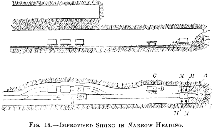
in the space of one minute. As soon as car, D, has been brought to the advancement, another empty car, E, is brought to the same point, C, reversed on its side, and waits until car, D, is filled and taken away again, etc. In one instance, 14 car-loads, each of 1 cu. m. volume, were taken away in 1.5 hr., which cleared the heading completely and allowed the drill-wagon to be brought in. Ten men are busy removing the debris, two of which number get at the extreme limit marked F, and their work consists in searching the debris for the dynamite cartridges which might not have exploded. Of the remaining eight men, four work to fill the car, as shown at M which takes 5 min.; they then rest for 5 min., while the second gang of four men come and fill the second car, etc.
Drilling is started not more than 5 min. after the removal of the last car-load. This result, which at first sight seems impossible, is only obtained by absolute discipline.
The man who knows that his only work at this moment is to connect the air-main to the drill-carriage does not do anything else; the men whose duty it is to screw the carriage tightly to the wall immediately jump to the right place.
The system has been adopted of low and wide gallery in the proportion of 1 : 2; the gallery being 6 ft. high by 12 ft. wide.
The rate of drilling is, 15 or 16 holes in 1.1 to 1.15 hours.
An engineer who recently visited this work says:
“ When I arrived at the heading it was 9.30 a. m. The holes were being prepared for blasting. The blast took place at 9.35 a. m.; 5 min. after the blast the men were in place removing the debris, and at a little after 11 a. m. the drill carriage was in place again and the rock-drills were working. It usually takes from 25 to 30 min. between the time at which the drilling is finished and the time at which the start is made to remove the debris ; that is to say, 25 min. for taking away the drill-carriage, cleaning the holes, loading with explosives and blasting. An additional 5 min. are consumed in getting the smoke away by means of the ventilator and then the men get to work at the debris. In order to assist the men a spray of water is discharged near the heading after the blast. This water is brought into the tunnel in a pipe placed within a larger pipe, which insulates it and keeps its temperature from being affected by the temperature of the tunnel.”
Drilling in the top heading is accomplished by means of two or three drills carried on tripods or on a horizontal bar, while hammer hand-drills are used generally for the enlargement.
Mucking-operations in the top heading are very simple, since all blasted material is dumped directly through the upraises into cars running on a siding in the bottom heading.
The operations of blasting, mucking, timbering, and hauling are performed without interruption and without interference with each other, and a special force of engineers is required in order to obtain such a result.
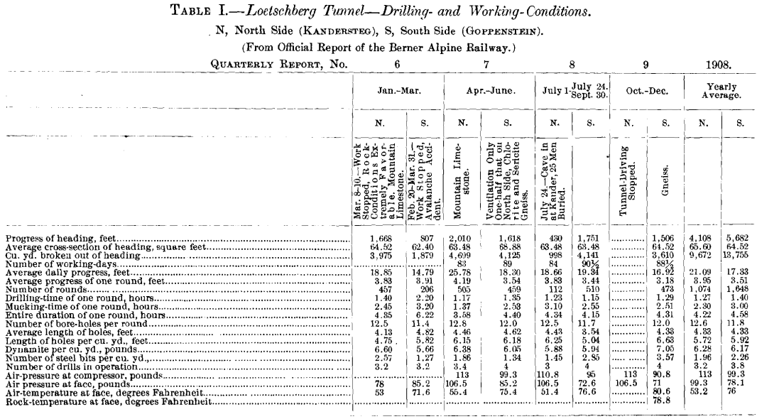
All employees and workmen are insured against accident or death, by the contracting company, and great care is therefore exercised in handling explosives and in operating the trains. Data pertaining to driving the headings are given in Table I.
Ventilation
Ventilation in the tunnel is obtained from two ventilators 11.5 ft. in diameter, having a capacity of 53,000 cu. ft. of air per min. at 5.5 oz. pressure. Each ventilator is belt-driven by a 175-h-p. electric motor, housed in a building at each portal, forming part of the permanent ventilation-system.
Air is taken in that part of the tunnel already completed through a canal of 68 sq. ft. area, made of hollow tiles, shown in Fig. 17, then through steel pipes to electric-driven ventilators running in series, and having a capacity of 6,300 cu. ft. of air per min. at 14 oz. pressure. These two ventilators are mounted on carriages, and are moved along as the work advances.
Openings are provided at intervals in the above-described air-canal so as to allow part of the air to escape in the tunnel.
Rock Temperature
In comparing conditions on the north and south ends of the Loetschberg tunnel, it is well to bear in mind that at the south end the rock is generally harder and the temperature higher. At the north end the temperature varies from 75° to 80° F., while at the south end it has reached a maximum of 110° F. It is also claimed that a remarkable organization of the working-force exists on the north end. The settlement at the south end was built by the Loetschberg Co. The winter there is extremely severe and dangerous. Three years ago, by an avalanche, seven men were killed, among them an American engineer named Merwarth, who was at the time installing the compressed-air machinery. Conditions of this kind do not favor the contractor in getting the best kind of labor. Kandersteg, at the north end, is practically a summer-and-winter resort, full of good hotels, easy to reach, and a more favorable labor-market.
At one time, when the north heading was making a daily progress in excess of the south heading, the contractors sent some of the drills from the north heading over to the south, thinking that perhaps the difference in progress was due to the drill, but the results were not changed. It seems plain that were it a question of machinery only, the machinery making the greater progress would be used throughout, but the difference appears to be one of natural conditions and of organization.
On the south side, after blasting, 12 connection-valves are opened for the rapid removal of the air in the tunnel. During drilling ventilation is also done with compressed air.
The official reports show that the quantity of air used for ventilation on the southern end was only about half that on the northern end, and it is generally said that the southern ventilating-system was not as effective as the northern, whereas the temperatures on the southern end were higher. The operating- force was compelled to use compressed air from the air-mains to increase the ventilation, which, in a measure, reduced the temperature, and decreased the pressure used for drilling. It is likely that in this way the efficiency of the drills may have been somewhat reduced. The working-pressures were : north end, 7.2; south end, 5.2 atmospheres.
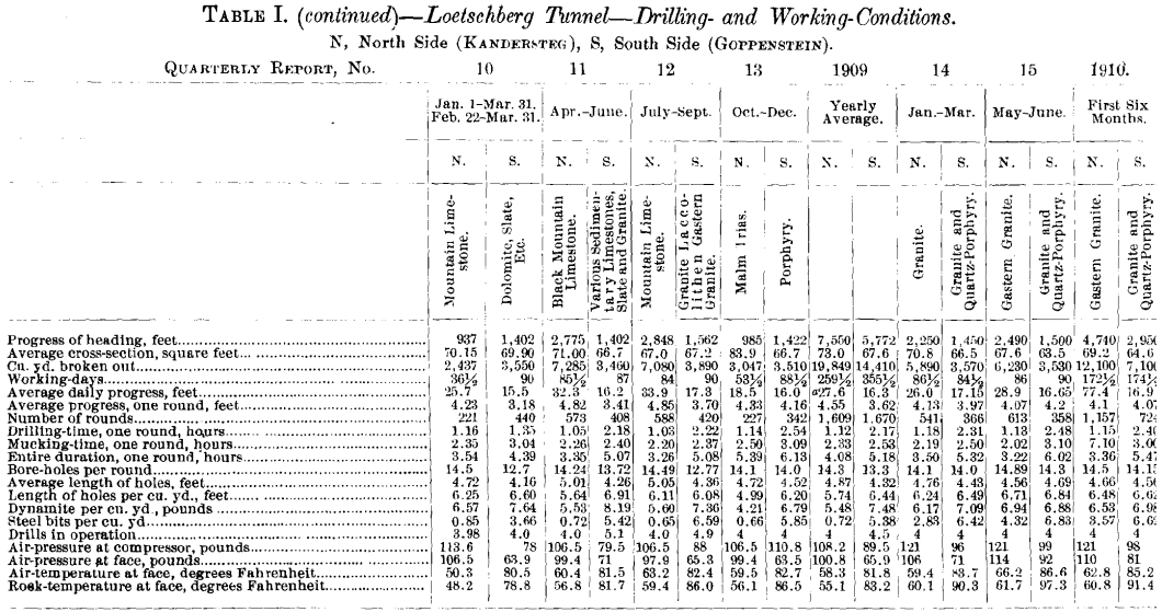
The nature of the rock was different on the two ends of the tunnel, as shown in Table I. An average of one steel was required in the north end for 1 cu. m. of excavation, while on the south end an average of from 5 to 7 was required for the same work.
The average consumption of steels for 2.5 years was : north end, 2.33; south end, 7.70 steels per cu. m. driven.
The report for the year 1910 shows that in the first part the rock encountered on both the north and south ends was practically the same, although the average drilling-time was much less on the north than on the south end. To explain this, the air-pressure on the north end during this period was 7.75, as compared with 5.7 atmospheres on the south end, which largely accounts for the difference. It must also be noted that the number of steels per cubic meter of rock removed was, on the north end, 4.65; and on the south, 8.61, which indicates either that the effect of the rock on the drill-bits was different, or that the blacksmith-work was unequal.
I wish to express my indebtedness to Eugene Lauchli, the able Swiss engineer, now living in New York, who has greatly aided in the preparation of this paper. I am also indebted to G. H. Gilbert; F. A. Choffel, of Paris; and to Dr. Henry S. Drinker, through his work on Tunneling; to C. R. King, in Engineering News; Tunneling, by Prelini; Practical Tunneling, by Sims and Clark; Modern Tunnel Practice, by Stauffer; and to various encyclopedias and published articles relating to the Alps.