
Table of Contents
Electrolytic determinations are now part of the routine of many commercial laboratories and means for carrying out such work will usually be found in every well-equipped metallurgical laboratory, no matter how small it may be. In determining copper, nickel, bismuth, etc., the electrolytic methods are far more satisfactory than the precipitation or volumetric ones, hence in a laboratory where ores containing copper are likely to be brought for analysis or where bearing metals or alloys, nickel, steel, etc., are analyzed means should be provided for electrolytic work.
Use of the Electric Lighting Current
Stillwell and Austin were, I believe, the first to suggest the use of the electric light current for the determination of metals in the electrolytic way, and the writer has found this to be not only sufficient for ordinary technical purposes, but also by far the most convenient. When available, it is much cheaper than batteries and saves the operator much trouble. The only disadvantage in connection with its use is the constant voltage which is usually 110 or 220. Indirect or alternating currents must of course be transformed to direct currents. This necessitates the use of a transformer, which may make the cost of installation of the outfit for electrolytic work so great as to make the use of batteries preferable to that of the electric light current.
It is of course necessary to reduce the strength of the current. For this purpose the resistance board shown in Fig. 51 and designed by the author is convenient and satisfactory. It consists of a stout board, 2 inches thick and 24 inches by 8 inches. This board should have its top covered by a piece of asbestos board, to guard against fire, etc., so that the apparatus may be left over night without danger. In a line down the middle of this board, with their centres 3 inches apart, seven porcelain keyless sockets or receptacles, b1, b2, b3, etc., should be fastened. The best form of receptacle to use is that shown in the cut. Single pole knife switches, a1, a2, a3, etc., are also placed three on each side, as shown in Fig. 51. At either end of the board a binding post d1 and d2 is placed. Each receptacle is connected to the next receptacle and also to one point of the switch, by means of short pieces of insulated copper wire. The end receptacles are also connected, each to a binding post. All the connections should be made as shown.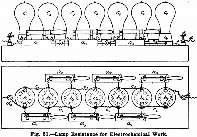
With this board should also be provided six 16-candle power lamps, six 32-candle power lamps, six 50-candle power lamps, and a safety plug of say 10 amperes. To use the board, connect one of the binding posts to one terminal of the electric light current and connect the other with one of the electrodes of the solution to be electrolyzed. Now, if a weak current is desired, screw 16-candle power lamps into the sockets and open all the switches. The current will then travel through all seven of the lamps, as follows: —from d2 through the lamp c1 and from this to the lamp c2, by means of the wire e1, and thence to the binding post d1 through e2, c3, e3, c4, e4, c5, e5, c6, e6, c7, in order. For a resistance of six lamps, remove the lamp c7 and place the safety plug in the receptacle b7. For five lamps, close the switch a6; for four lamps, the switch a5; for three lamps, a4; for two lamps, a3 and for one lamp, a2.
For stronger currents the lamps may be put in parallel. To do this, take out the safety plug from close all the switches and put in from one to seven lamps, according to the strength current desired. Seven lamps will give about 3.5 amperes, while two lamps will give about one ampere. For yet stronger currents put in the 32-candle power or the 50-candle power lamps. For very weak currents, use another board and shunt the current through this around a light. For analytical work, however, the above board is sufficient and only 16-candle power lamps need be used, unless the rotating anode is to be employed, when 50-candle power lamps will be needed, since the currents for this work are much stronger.
The above board provided with 16-candle power and 50-candle power lamps will give a range of current of from about 0.07 ampere to about 11.0 amperes. The resistance of the board can be calculated, sufficiently near the truth for analytical purposes, by assuming for a no volt circuit, that the 16-candle power lamps have a resistance of 220 ohms; the 32-candle power lamps, 108 ohms; and the 50-candle power lamps, 69 ohms. If, therefore, seven 16 C. P. lamps are in series, according to Ohm’s law:
Amperes = volts/ohms or Amperes = 110/220 x 7 = 1/14
Or the resistance of the lamps is 1/14 ampere or 0.07 ampere. If now the seven 16 C. P. lamps are in parallel the resistance will be no 110/220 x 7 or 3.5 amperes.
Instead of calculating the resistance of the board, it is preferable to determine it by means of an ammeter. This may be done once for all, and the values for each combination of lights recorded in a note book, or the measuring instrument may be introduced into the circuit while the determinations are being made. This latter plan is preferable, but necessitates the possession of an ammeter by the laboratory, while in the former event, the work of determining the resistance may be done in some electric light station, or by some friendly electrician.
To start with a low resistance and increase to a greater, place all seven lamps in the board and open all the switches and connect up the apparatus with the terminal wires. Now take out the lamp c7 and screw the safety plug in the receptacle Then close in turn the switches a6, a5, a4, a3, and a2. Do not close the switch a1, however, or short circuiting will take place. Now take out the plug from the receptacle b7 and unscrew all the lamps, except c1, from the receptacles, far enough to break the contact. Close the switch and screw in the lamps to make contact one by one.
To avoid short circuiting, the connection between b1 and d2 or between b7 and d1 should be made with fuse wire, or another lamp receptacle may be put in between the receptacle b7 and the binding post d1 connected to b7 and d1 by pieces of wire, and a safety plug kept in this all the time.
The board may be fastened to the wall, or a cord and plug socket may be fastened to it so that it can be put away in a desk when not in use. When wanted the board can be readily attached to the current by screwing the plug socket into a lamp receptacle, on the wall or hanging from the ceiling.
Gravity Cells
When the electric lighting current is not at hand, batteries must, of course, be used. For ordinary analytical work six crowfoot or gravity cells will be found sufficient and these can be arranged in series or in parallel as the case may require. No resistance board is needed, as the strength of the current can be controlled by the number and the arrangement of the cells themselves. Where currents of greater strength than one or two amperes are needed the bichromate cell should be used in place of the gravity cells. When weak currents are to be used, however, nothing will be found so easy to take care of as the crowfoot or gravity cells. These may be arranged in a closet under the work-table on which the electrolytic work is done. They should be connected up to a board as shown in Fig. 52, so that they can be readily arranged in any way desired.
This board consists of two narrow strips of copper or brass, E and D, running along the front edge or on the side of the work-bench just under the top. These strips should have a binding post at either end of which the wires leading to the anode and cathode of the solution to be electrolyzed should be connected, and should be about 6 inches apart. Equidistant between the two strips of metal twelve short pieces of brass spring a1 b1, a2, b2 etc., should be screwed into the board. These springs should be about 3½ inches long and should reach to either the strip D or E. Each pair of springs should be placed so that the adjacent spring of the following pair can rest on the screw holding the spring itself to the board. That is, referring to Fig. 52, the spring a2 should be so placed that it can be swung around so as to rest on either the copper strips E or D or on the screw holding the spring b1 to the board. Each spring should be connected to a pole of a
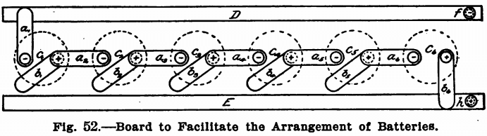
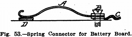
battery. The springs a1, a2, a3, etc., should be connected to the zincs of the cells, and the springs b1, b2, b3, etc., should be connected to the coppers of the cells. Fig. 53 shows an elevation of one of the springs. A is a piece of brass spring with a round hole bored in one end and the other turned up to form a handle. This spring is fastened to the table by means of the brass screw B, and should be held in place by two washers, as shown. C is a piece of copper wire connecting the spring with the battery. D is the long copper strip running the length of the table.
With the springs in the position shown in Fig. 52, the six cells are in series. The spring a1 connected with the zinc of cell c1 rests on the strip D, and the spring b2 connected with the copper element of cell c6 rests on the strip E, while the copper elements of the cells c1, c2, c3, c4, and c5 are connected to the zinc elements of the next cell by means of the springs a2, a3, a4, a5 and a6. The springs b1 b2, b3, b4 and b5 are out of service and rest merely on the wood.
To connect in parallel, the springs marked a1, a2, a3, a4, a5 and a6 should rest on the strip D and those marked b1, b2, b3, b4, b5 and b6 should rest on the strip E.
A battery of six crowfoot cells can be bought for less than $5.00.
Storage Batteries
Storage batteries are a very convenient source of current when means for charging them is at hand and a board like that described above will be found very handy for connecting them up. Their relatively high voltage and amperage make them more suitable than any other form of battery, while their discharge is very steady and dependable. They give a voltage of about two. A higher voltage is obtained by adding more cells in series, (i. e., the positive pole of one to the negative pole of the next, and so on).
Cells can be obtained for any amperage capacity, the amperage required to exhaust the cell in eight hours being the standard. A cell of two and a half amperes for eight hours discharge is large enough for ordinary use, although it is convenient to have cells of a larger capacity so as to allow longer intervals between charges.
Unfortunately, storage batteries cannot be used unless there is some means at hand for charging them, and moreover they are very delicate and need careful attention to prevent them from being ruined. Explicit directions accompany the batteries, and if means for charging them, such as the lighting circuit and a rheostat sufficient to reduce the current to the normal charging rate, are at hand, nothing better for electrolysis can be obtained.
A description of storage batteries, their use and care is beyond the range and scope of this paper; an excellent chapter on storage batteries, written by Prof. F. B. Crocker, will, however, be found in a little book, “Practical Lessons in Electricity,” published by The American School of Correspondence at Armour Institute of Technology, Chicago, III., which anyone interested in the subject of electrochemistry will do well to procure.
Rheostat
Where batteries or storage cells are used some means other than the lamp board previously described must be provided, since the resistance of this is far too great for such sources of current. Rheostats are manufactured for this purpose, made up with coils of resistance wire, and a movable arm that can be placed so as to allow the current to pass through as much of the resistance as desired. Such rheostats are best purchased. They should be constructed so that they will cut down the current from one cell, from full strength to about .105 ampere, in from ten to twenty equal steps; and be able to withstand the full current from all the batteries at once.
A water rheostat makes a very cheap and simple means of controlling the current. A glass or earthenware jar of about three quarts capacity is filled with a very weak solution of sulphuric acid. Two arc lamp carbons are attached to the terminals of the current in series and dip into the solution. The farther the carbons are apart the greater the resistance. By fastening one on the edge of the jar and hanging the other on the edge with a clip so that it may be placed anywhere, an excellent rheostat is obtained. The resistance in the solution can be decreased by
adding acid, and increased by adding water. The size of the jar, etc., will depend upon the conditions of the circuit, and are easily found by experiment.
Arrangement of Cells
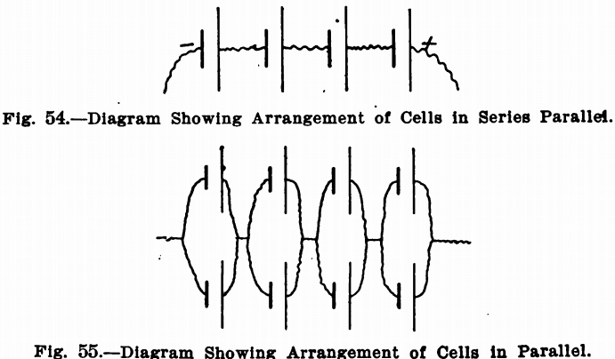
The diagrams show how certain results can be obtained by altering the arrangements of the connections. It must be noted that a voltage of above the desired figure must be obtained by adding batteries in series and then cutting down to the right point by the rheostat. As mentioned before, by the series arrangement, the cells add their voltage to the circuit, but the amperage remains about the same as for one cell. Fig. 54 represents the series arrangement, in which the short thick lines represent the zincs and the long thin lines the coppers. The irregular lines represent connecting wires. If 3 1/3 volts are desired, the voltage is brought up to four by adding four cells, and then reducing the voltage to 3½ by the rheostat. This arrangement will give an amperage depending upon the resistance in the circuit and electrolyte. It should in most cases be sufficient, since the current usually required is very small, but if it is not, the amperage can be doubled by adding an equal number of cells in parallel. Fig. 55 represents this arrangement. This is a series parallel arrangement, giving the same voltage as in Fig. 54, but twice the amperage. It will be noticed that there are four groups of cells. In each group there are two cells with the zinc connected to zinc and the copper to copper. But the zincs of one group are connected to the coppers of the next, and so on. In making these arrangements, the same proportions always hold true, so that any combination of cells, to give almost any current, can be obtained.
Electrodes
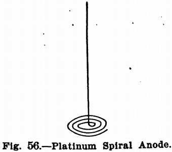
In electrochemical analysis, a platinum wire or spiral is usually used as an anode, Fig. 56, and a platinum dish, cone or cylinder for the cathode. When the deposit to be weighed is formed on the anode the cone or dish is used as the anode, and the spiral for the cathode. Aluminum cathodes have been proposed for copper analysis, and even copper ones would probably give satisfactory results in this case. When obtainable, however, platinum should be used.
The most satisfactory cathode is a small platinum dish weighing about 30 to 50 grams. When large volumes of solutions have to be electrolyzed the cone or cylinder must of course be used and the solution held in a beaker.
Stands
Figure 57 shows a convenient stand for use when a platinum dish is employed as a cathode. It consists of a wooden block, A, about 2 inches thick and 4 or 5 inches square, depending on the size of the dish. A round hole about an inch deep and about 3 inches in diameter should be gouged out of this and a triangle, C, of copper wire fastened above this, as shown in the illustration, by two round-headed screws f1 and f2, and a binding post, e. A light wooden frame, B, should be fastened to the block, A, and the binding post, d, screwed midway in the top piece of this. The binding post, d, should be for two wires and the second
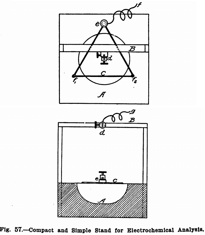
hole should be directly over the centre of the triangle. The dish to be used as a cathode should rest on the wire triangle and the platinum wire to be used for an anode should pass through one hole of the binding post d. The wires carrying the current can then be attached one (+) at the vacant hole of the binding post d and the other (—) at the binding post e. When a cone or a cylinder is used as a cathode, the block, A, should be made solid, without the hole, and the frame should be high enough to permit a beaker to be moved in and out under it comfortably. Another binding post similar to d should then be fastened beside d to hold the cone.
Very often supports similar to retort stands, except that the supporting rod must be of heavy glass to avoid short circuits, are
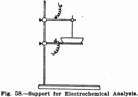
used. Figure 58 shows such a stand. The supporting arms or rings can be obtained with binding posts to receive the terminals, and must be of bright metal, not painted. If the platinum dish is used it sets directly upon a ring clamped to the glass supporting
rod. It is preferable to provide this ring with three platinum points for contact with the dish. If the dish is to be heated, a sheet of asbestos is fastened on the under side of the ring in order that heat may be applied to the solution without the dish coming in contact with the bare flame.
Measuring Instruments
For measuring the current there will be needed an ammeter and a voltmeter.
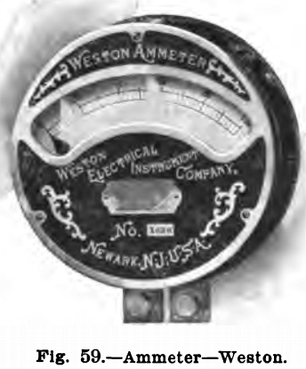
The Ammeter, Fig. 59, measures the amperage or amount of current. The instrument should read from 1/100 of an ampere to at least two. It is connected with the circuit in series, as in Fig. 61.
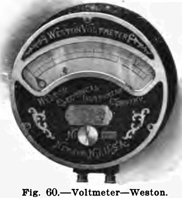
The Voltmeter, Fig. 60, registers the volts or force of the current. It should read from to 10 volts. It is placed as mentioned before in parallel, and between the precipitating vessel and all other parts of the circuit.
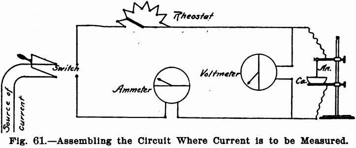
Where the current is to be measured, the proper method of assembling the circuit is shown in Fig. 61. It will be noted that the rheostat and ammeter are in series and the voltmeter in parallel. There must be no other instrument between the voltmeter and the precipitating dish, as the true voltage between the anode and cathode will be given by this position only.
Rotating Anode
Many electrochemical determinations can have the time necessary for complete deposition of the metal greatly shortened by rotating the anode. Means for doing this are described below. For the cathode a platinum dish is best suited.
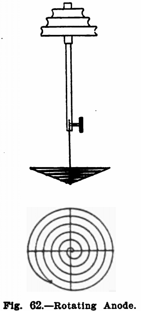
The anode used is a spiral about two inches in diameter, made of heavy platinum wire. It is made slightly bowl-shaped so that it will remain immersed in the liquid in spite of the funnel-shaped form assumed by the latter on rotating the anode. Figure 62 shows its construction.
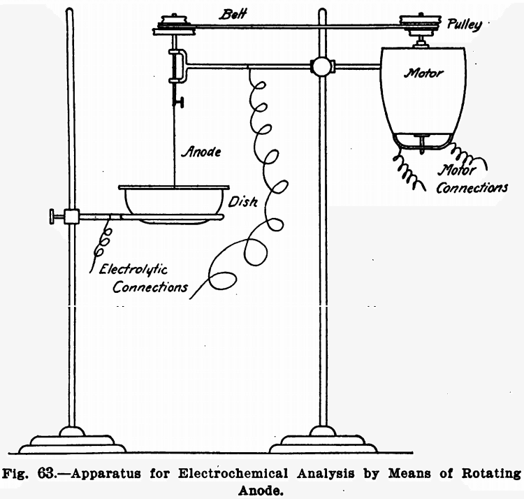
Any suitable means for revolving the anode may be used providing the rotations per minute are high enough. A water motor, electric motor, or even power derived from shafting will answer. But undoubtedly an electric motor run by the lighting circuit is the most convenient. The anode is driven by a small round belt, and the use of cone or stepped pulleys will be found convenient, as several speeds can be gotten in this way. Figure 63 shows the general arrangement.
The anode should revolve at about 700 revolutions per minute.
When many determinations have to be made at the same time, one motor may of course be made to do for all by crossing the belt after each pulley. In this case the mortar and bearings of the anodes should all be mounted on the same framework.