
Table of Contents
The chemical laboratory in our industrial establishments has remained a factor of minor importance, and, for this reason, not only has progress been permitted to lag, but the methods of analytical work have been carried on along individual traditional lines. Some works-laboratories are equipped with such conveniences as Gooch filters, suction-pumps, compressed air, shaking-machines, centrifugal machines, crushers, etc., yet there is much room for improvement, particularly in laboratories of metal-smelting and refining plants, in which long series of filtrations and stirrings are performed singly by hand in a slow and laborious manner. There are also many other instances in which collective handling appears rational. As a rule, the chemist wastes much time by such manual labor, which, in a modern establishment and under up-to-date management, could be more advantageously applied to useful chemical work; and such higher chemical work is gradually and surely becoming recognized as an essential extension of old-time methods of assaying. While it may be said that in some laboratories, boys and not chemists do the manual labor, it should be borne in mind that all chemical work requires care and accuracy, and in these respects boys are naturally a source of concern to the responsible chemist. Moreover, the cheapness of labor is largely offset by the increase in the expense-account of laboratory materials, caused chiefly by breakages resulting from carelessness.
The present ruling principle in shop and factory, induced by conditions of keen competition, is to do the greatest amount of work in the shortest time; or in other words, to secure the greatest output at least cost, a condition which has generally necessitated the substitution of machinery for manual labor.
Having been authorized to build a new laboratory, I decided to make its equipment superior to any that I had seen in this country or abroad. As in many others, the bulk of the work done in the works-laboratory of our company consists in the routine of a few methods applied to many determinations. The value is determined of the copper, silver and gold contained in the crude material that is handled in the works. This analytical work is commonly called assaying,— an old and useful art which, however, is too often lightly considered by those having an excessive knowledge of chemistry and metallurgy.
Laboratory Design and Floor Plan
Concerning the general arrangement of the laboratory, you need read a paper entitled The Equipment of a Laboratory for Metallurgical Chemistry in a Technical School, as it has pointed out the desirability of arranging a laboratory in a technical school in such a manner that the greatest amount of work can be done by each student. This systematic arrangement is equally desirable in the works-laboratory, and the one under consideration has been so designed that the number of movements required from the beginning to the end of every operation has been reduced to a minimum.

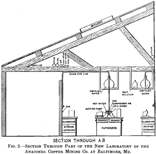
The hygienic arrangements of the room should also be given proper attention, especially the ventilation, which as a rule is only made satisfactory by the proper construction of the hoods. At our new works-laboratory the two-compartment brick hood is plastered on the inside and has a tile floor, the openings into the laboratory being supplied with vertical sliding glass doors. The stack, 21 ft. high, is directly over the slate roof of the hood, which tapers from two sides toward the openings of the stack. The cross-section of the openings from the hood to the stack equals that of the free space in the stack. The hood is built against the wall of the building, and parallel to this wall is a second one, leaving a free space of 4 in. between them which communicates with the hood by a number of 2- by 4-in. holes, along the floor, and with the stack by a larger opening at the highest point of the hood. This construction gives a good draught along the floor, as well as at the apex of the hood, and, regardless of the amount of copper that is being dissolved with nitric acid, there is never any noxious odor of “ red fumes ” in the workroom of our laboratory. A plan and part section of the new laboratory, are given in Figs. 1 and 2 respectively.
With regard to cleanliness of work in the laboratory, my first teacher in practical chemistry, Hermann von Fehling, used to tell his students, that “Der Chemiker muss im Frack-Anzug arbeiten koennen.” This remark made a lasting impression upon me, and I have always disliked the sight of black or yellow hands, or of work-clothes having many spots and holes. It is not given to everyone, however, to be as tidy as Fehling was, but it is possible to aid natural defects by artificial means.
Handling Beakers and Acids
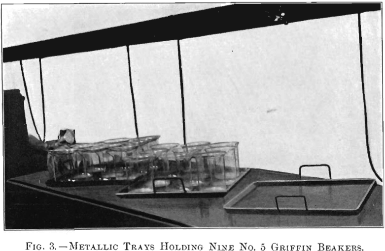
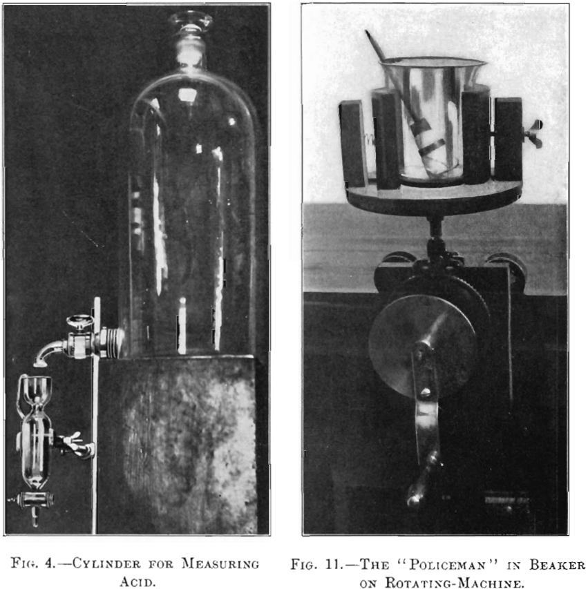
As already stated, assaying forms the bulk of the work at the Baltimore laboratory. Scores of silver-determinations and hundreds of scorifications and cupellations for gold are often made. Silver, and sometimes gold, is determined in the metallic copper-material by what is commonly known as the combination method, which consists in dissolving both copper and the contained silver in nitric acid, leaving the gold as a metallic residue. The silver is re-precipitated in the form of chloride and, with the gold, is separated from the copper solution by filtration. The incineration of the filter, scorification with metallic lead, and cupellation with a subsequent parting of the two precious metals, completes the assay. We have simplified this operation first by the introduction of metallic trays to hold the No. 5 Griffin beakers, thus avoiding handling them either singly or in pairs. Each tray, shown in Fig. 3, holds nine beakers, and, as soon as the copper has been dissolved, the tray may be placed directly on the fire in order to expel the nitrous fumes by boiling the solutions. The acid used to dissolve the copper is kept in a 5-gal. bottle, having a glass cock, or spigot, with a 0.25-in. orifice, through which the outflow is very rapid. From this bottle the acid is tapped into a specially designed measuring-cylinder shown in Fig. 4, provided with a stop-cock similar to that of the bottle, which allows the acid to be tapped into the beakers, without dripping, in a neater and cleaner manner than can be done by pouring from a bottle, beaker or cylinder.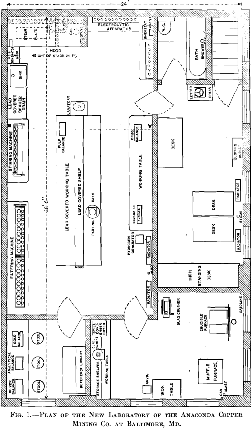
After the copper solutions have become cold and the proper quantity of sodium chloride requisite to precipitate all the silver has been added, it is absolutely necessary to stir the mixture in order that the reaction shall take place throughout, and that, after adequate settling, none of the silver chloride will run
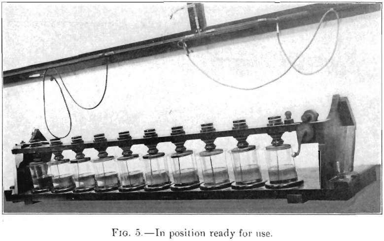
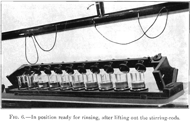
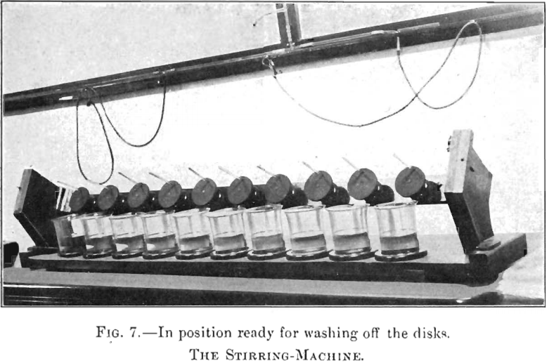
through the paper during the subsequent filtration. The stirring of a large number of solutions by hand occupies much time and is very tedious, but omitted, the determination becomes faulty. Figs. 5, 6 and 7 illustrate a stirring-machine which obviates all the difficulties incident to the manual operation of stirring and, by its use ten solutions can be stirred in the same length of time occupied in stirring one by hand, and there is no splashing of solution or breakage of beakers.
Fig. 5 shows the machine ready for use; Fig. 6 shows the position after the stirring-rods have been lifted from the solutions and are ready to be rinsed; and Fig. 7, the position assumed after the rods have been rubbed off, the disks holding them and forming a cover to the beakers, now being ready to be washed. This latter operation, however, is generally superfluous, for very seldom does any of the solution reach the covers.
The characteristics of this stirring-machine are the three- based feet; the convenient driving-gear on the right, which admits of the ready application of mechanical power; the slack take-up for the belt on the left; and the rubber disks which hold the rods and form covers to the beakers. The action of the machine is made universal by having several holes in each disk so that the position of the rods will conform to any size of beaker. The separate construction of both beaker-stand and stirring-stand permits a ready change of a set of beakers and allows the rods to remain a permanent part of the whole. Descriptions of stirring-machines are given in some catalogues of manufacturers of chemical apparatus, but they seem to lack the essentials necessary for successful manipulation.
Filtering Equipment & Supplies
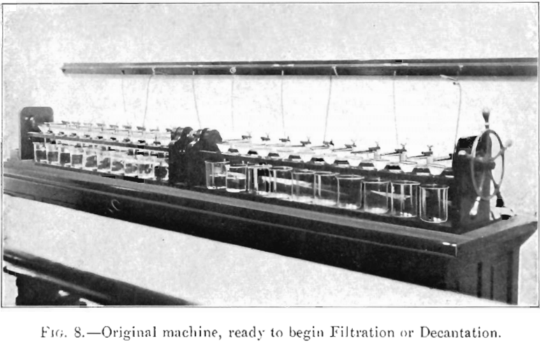
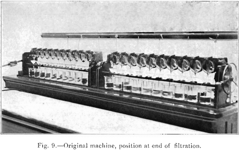
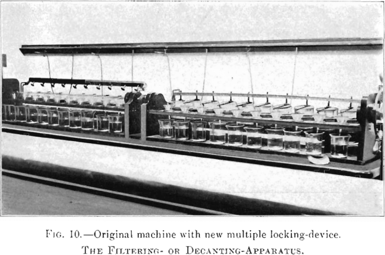
The construction and operation of the filtering or decanting apparatus are illustrated in Figs. 8, 9 and 10; and by its use 20 filtrations can be performed with perfect ease, and without the least danger of loss by splashing or breakage. The beaker- rack is tilted by means of a handwheel on the right, retrograde motion being prevented by a ratchet. The point of rotation of the whole series of beakers lies some distance from their lips, about at the end of the glass rods that guide the stream of liquid to a definite point in the filter, an arrangement which is essential for steady pouring. The lifting of the load is aided by a counterpoise on the left. By the use of this apparatus the filtering can be done leisurely with one hand, so steadily that the precipitate remains undisturbed until all the clear liquid is poured off, and the time of the whole operation is greatly shortened. Figs. 8 and 9 show the machine as originally constructed, with a locking-device for each beaker and rod, consisting of an arm pressed downward by a spring, and free to rotate vertically within an angle sufficient to clamp, as well as to allow it to sweep horizontally over the rod and beaker, the horizontal rotation also being entirely free. Fig. 10 presents a locking-device on the same machine by means of which ten beakers and rods are locked simultaneously. It is a matter of taste which arrangement is the more satisfactory. The beaker-rack and the filter-stand are adjustable to several sizes of beakers and funnels, and the machine can be made for any number of beakers. Light wooden trays are provided to carry the beakers, in sets of ten, to and from the apparatus.
Table I., containing the results of a test recorded by one of my assistants, shows the difference in time between the new method of mechanical filtration and the old method by hand. Twenty beakers, each containing between 275 and 300 c.c. of solution, were used in the test.
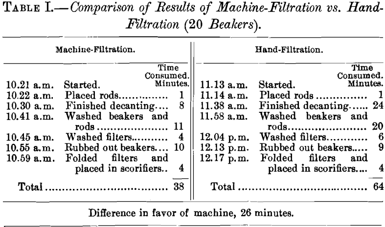
I have decanted ten beakers, each containing from 275 to 300 c.c. of solution in 4 min. 30 sec., the solutions being run through a double S. & S., No. 597, 12.5-cm. filter.
In connection with the work just described, we have entirely dispensed with the well-known wash-bottle, on account of the unnecessary physical strain involved in its use, as well as its unsanitary character in many instances. The distilled water, contained in carboys placed about 4.5 ft. above the floor-level, is siphoned into a system of glass-tubing, extending throughout the laboratory wherever the water may be needed. This glass-tubing is provided with numerous T-connections to which are attached rubber-tubes, having pinch-cocks and glass nozzles at their ends, which permit the direction of a stream of water to any desired point. The water in the overhead carboys is replenished by forcing up through a glass tube, by means of compressed air, a new supply from another carboy (in which it has been condensed) placed on a carriage on the floor.
When the filtration is complete and the precipitates have been washed out of the beakers, the latter must be rubbed out with paper in order to be sure that neither silver chloride nor gold is retained on the walls of the vessels, perhaps by a little oil often contained in the samples, or by the drying and hardening of small particles of chloride above the surface of the solution. In order to facilitate this cleansing, we have designed a machine in which the beakers are rotated. This machine is on rollers, and runs on rails fastened to the table in front of the filtering-apparatus, and may be locked at any desired point. The cleansing is done by means of a “ policeman,” Fig. 11, which consists of a rod having a cork fastened at one end, over which is clamped a piece of filter-paper, held in place by a conically-cut ring. The paper thus fastened is rubbed along the bottom and sides of the rotating beaker. For each beaker a fresh piece of paper is quickly clamped to the cork.
Assay Furnace Supplies
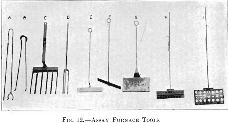
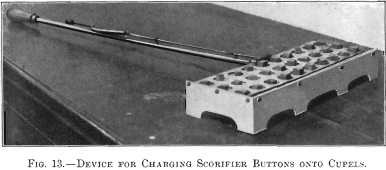
The implements used in performing the furnace-work in assaying are shown in Fig. 12. A and B are the traditional tongs, universally used for handling singly the scorifiers and the cupels. The former has been entirely replaced with a fork, C, with which a set of 20 scorifiers can be handled at one time. In silver assaying each set of scorifiers is placed in the muffle twice and taken out twice; first, put in the muffle for the incineration of the filters, then taken out for the addition of the test-lead, then returned for scorification, and finally taken out for pouring the slag and molten lead into the molds. By the use of the fork, which works perfectly if the muffle be properly supported so that it will not sag to any marked extent, 60 handlings are reduced to three. Four scorifiers constituting a longitudinal row in the muffle are poured at one time by means of a pair of tongs, D, and with a little practice the pouring is made just as easy as with a single scorifier. It is necessary only that the molds correspond to the arrangement of the scorifiers and that the pockets are shallow. The cupels are placed into, or taken from, the muffle in sets of one or more rows, by means of the tools, E, F and G., an idea which, I believe, was first put into practice by my brother, Richard Keller, of Durango, Colo. E and G are sharp-edged shovels, the latter having upturned sides. F is a rabble, with which the cupels are raked onto the shovel, and removed thence to the place where they are to be deposited by placing it behind them and withdrawing the shovel. The tool, H and I, is entirely new, and by its use, one or more rows of cupels in the muffle may be charged with the lead-buttons from the scorifiers. Fig. 13 shows the idea of the device more clearly. It comprises a top sliding-plate with openings corresponding exactly to the position of the cupels. The openings in the lower plate correspond exactly with those of the upper one; the plate, however, rests on two adjacent sides extended downward at right-angles to the plate and to each other, thus forming two closed sides of the instrument; one at the front, and the other at the right-hand side. The height of these sides is such that, when resting on the bottom of the muffle, the bottom plate will be some distance above the cupels and, by a slight pull forward and a push to the left with the handle of the instrument, the set of cupels will be perfectly aligned in both directions, and the apertures in the lower plate will exactly cover the tops of the cupels. The lead-buttons are placed in the apertures of the upper plate and rest on the lower plate before introducing the instrument into the furnace, and when it is placed over the cupels, which have been properly aligned in the muffle, the upper plate is pushed forward to a stop-point, bringing the apertures of the two plates to register, thus causing the lead-buttons to drop down into the cupels. The handle of the upper plate runs through guides fixed to the handle of the lower plate; both handles are connected with a spring, which acts as a brake when the upper plate is pushed forward to drop the buttons, and also serves to bring it back into its original position, in which the buttons cannot drop through the apertures in the lower plate.
Charles Tookey first recommended the use of hydrochloric acid (1 HCl.aq, 2 H2O) instead of a brush for cleaning the buttons, and for this purpose a small silver dish and tray having perforated pockets give excellent satisfaction. By the use of this device 50 or more beads at a time can be treated, washed and dried without transfer.
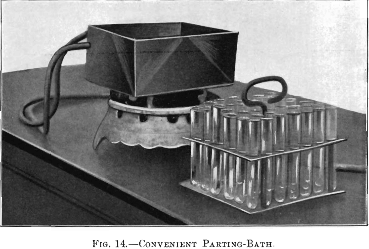
Fig. 14 shows a very handy parting-bath; which though old in principle has not been in general use. The vessel is a constant-level water-bath and the tray an ordinary test-tube holder. The silver beads to be parted are dropped into the test-tubes, and the latter filled with dilute nitric acid of a strength of one of acid (sp. gr. 1.42) to 9 of water. The water in the bath is first brought to the boiling-point before the tray with its contents is set into it. Treated in this way, the gold almost invariably remains in the form of a small coherent bead, even from an alloy as low as 1 part of gold to 500 of silver.
I have recognized that the system of handling everything in sets was incomplete as long as I was unable to take a whole set (20) of scorifiers from the muffle and pour their contents simultaneously into the molds. Recently a tool for that purpose, shown in Figs. 15 and 16, has been perfected. It is composed of quintuple tongs, corresponding to the five longitudinal rows of scorifiers in the muffle. The lower part of each pair of the tongs consists of a fork, on which the scorifiers rest, and one of whose prongs is rectilinearly extended through two bearings in a frame, and held in position by collars. This extension is free to revolve in the bearings, and forms the axis of rotation of the tongs. To each of them is attached, at right angle, a lever, extending upward at an angle of 45°, and all the levers are connected by slotted joints to a cross-rod. Therefore, if by means of a crank, fastened to the end of one of the extended prongs, one of the forks is turned and the scorifiers tilted to the desired angle, the others perform the same rotation. The center of gravity of the scorifiers lies to one side of the rotation-point, and they would therefore, on being lifted, tilt in that direction; this motion, however, is prevented by the cross-bar resting against a post at that end of the frame toward which the inclination tends.
The scorifiers are clutched by the upper prong of the tongs, which is fastened to a spring on a post of the fork below, and which is free to move in a vertical plane; the pivotal point
lying over the spring and post. By bringing pressure on the extended ends of these clutch-bars behind the pivot, their other end will rise from above the scorifiers, and thus release them, or permit the placing of them onto the tongs. The pressure exerted on the rear ends of the clutches is accomplished by means of a cross-bar fastened to a spring-bar, which is itself
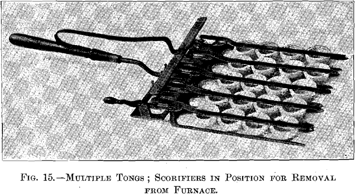
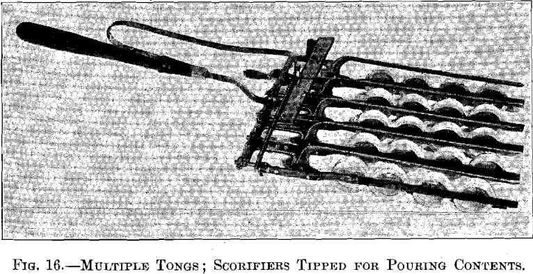
riveted to the handle of the instrument. These details are plainly shown in Figs. 15 and 16. In pouring the contents of the scorifiers, the frame of the tool rests on the edge of the mold, leaving the tongs free to turn.
The introduction of the new system of manipulation described in this paper has resulted in economy in several ways. Much labor has been saved; breakage of expensive glass-ware has been very largely eliminated; and the time of the furnace- work, and, consequently, the consumption of gas, have been much reduced. Furthermore, the gain has been a moral one, and work formerly regarded as tedious has become more of a pleasure; especially since the sojourn in the furnace-room during the hot summer months has been rendered cooler by being greatly shortened.
The appliances described in this paper may eliminate the laboratory-boy, but if not, they will make him more reliable. They also increase enormously the quantity of chemical work that one man can do in a day. In the small domain of our laboratory the change from the old systems to the new is considered to bear about the same relation as the change from the ancient horse-car to the modern rapid transit.
In conclusion, I take pleasure in acknowledging the efficient collaboration of my assistants, Mr. Albert Ferrell and Mr. K. W. McComas, the former having shown himself particularly useful as a skilled mechanic in the construction of the various improvements.