Table of Contents
Block Caving has been developed to a high degree of efficiency in the last two decades and more particularly since World War II. At the Jeffrey mine of Canadian Johns-Manville Co., in the Eastern Townships of Quebec, several innovations have increased production and decreased costs. Asbestos ore is produced at the rate of 10,000 tpd from an underground operation supplemented by a large open pit that has been mined since 1881.
Slusher Drift Development
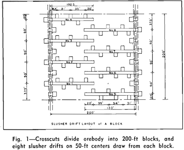
Originally slusher drift development was conventional, advancing the drift full 10×13-ft size at 6 ft per round. This proved dangerous and costly because the weak fractured rock of the orebody cannot be left raw for any length of time without its reacting with air to cause spalling. With this method of drift development ground conditions were worsened by many blasts and the length of time it was necessary for the drift to remain open.
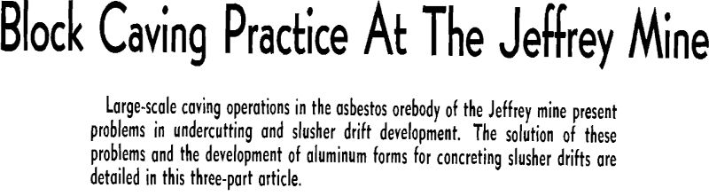
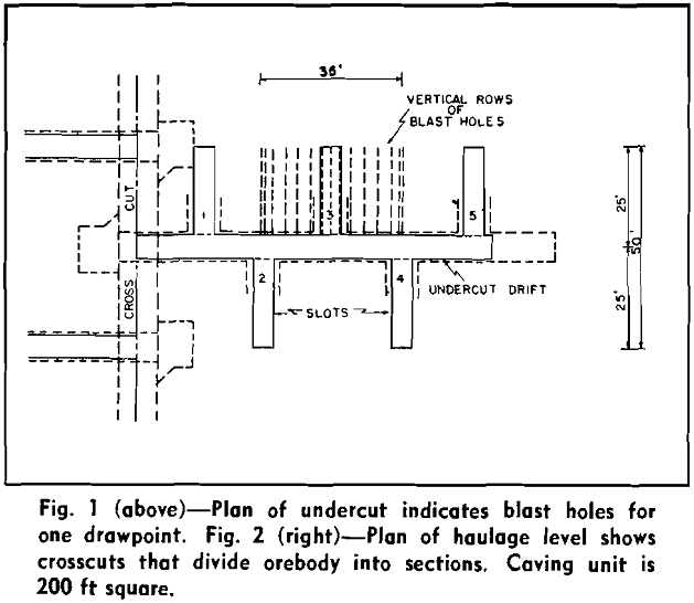
Crosscuts at right angles to the main haulage drifts, which cross through the center of the ore-body, divide the ore into 200-ft blocks. Eight slusher drifts on 50-ft centers draw from one block. The slusher floor is 11 ft above the rail, inclined at 1 pct grade, and the top is 18 ft below the undercut. The finished slusher drift is 102.5 or 120 ft long, depending on whether it is north or south of the crosscut. Drawpoints are staggered on each side at 17.5-ft centers. The completed drift is concreted and has an inclined ramp and a vent at the back.
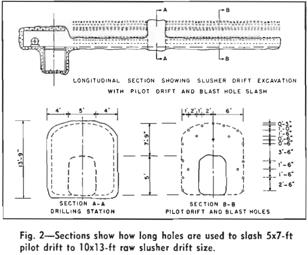
This excavation having been completed, a concrete floor 1 ft thick is poured the full length of the slusher drift. In the first 20 ft, 65-lb rail is placed in the concrete for wear protection. This concreting is done before the rest of the slash is blasted, because it is more economical to scrape the rest of the muck on a smooth floor, and the excavation provides the space required for blasting the remainder of the slash.
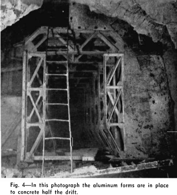
Before any more blasting is done, this opening or portion of the slusher drift is concreted, with recesses left at intervals for construction of drawpoints. Because of the quantity, concrete is poured on a mass production basis. Aluminum forms are used (see Part III) and concrete is placed behind them with a pneumatic Press-Weld placer. Concrete of at least 4000 psi (after 28 days and without reinforcing) is desired. A minimum of 18 in. of concrete is used. Reinforcing is not used because there has been experience of blasting vibration breaking the bond with the concrete and causing lines of weakness.
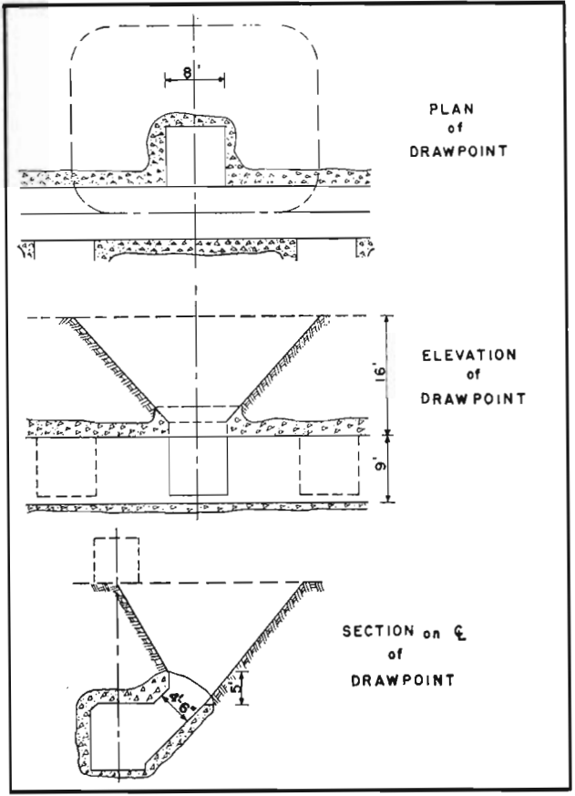
The drawpoints are among the last steps of developing a slusher drift. Because of bad ground condition it is necessary to develop the slusher drifts in sections and, for the same reason, to excavate and concrete the drawpoints separately. The excavation is made high enough to allow for an opening 8 ft x 4 ft 6 in. when concreted and at least 5 ft long.
Undercutting Technique
Undercut development follows an advancing panel of slusher drift units 100×50 ft in area. This is further broke down into areas 35×25 ft over individual drawpoints, each of which is prepared for undercutting as a self-contained blast, and drawpoints for each slusher drift are grouped for simultaneous undercut blasting.
The undercutting method now in use has served for the last six blocks with a minimum of modification. It is flexible enough to cope with all ground conditions encountered, except that extremely soft rock or extremely hard rock, and especially mixtures of the two, require special attention.
An undercut drift is driven directly above and parallel to each slusher drift. It is kept to a minimum cross-section and is opened no sooner than necessary to allow a continuous sequence of under-
cut preparation. It is often supported by steel sets and occasionally gunited as required. The undercut is drilled from this drift in a continuous pattern designed to progress from the bottom to the top of the slot and then out to the sides of the excavation. All drilling is completed before any blasting is started and, once started, blasting pauses only long enough to assure the complete breaking of the slot before proceeding with the rest of the holes.
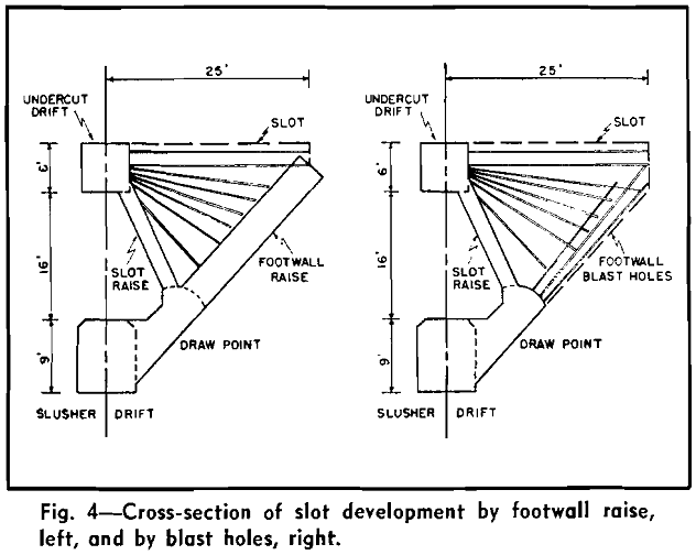
The slot raise is drilled downward from the undercut drift to break through on the centerline of the drawpoint below. The slot raise and the footwall raise then form a vertical V at right angles to the undercut drift from the undercut down to the mouth of the drawpoint.
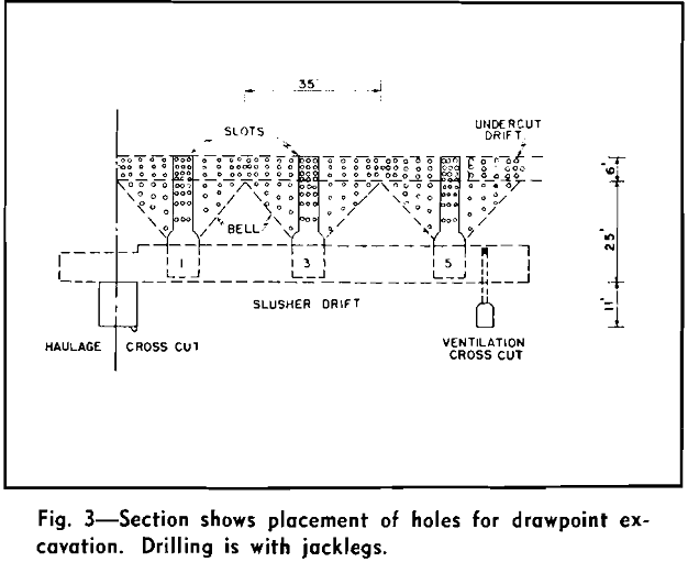
Each drawpoint is prepared as an independent unit to be blasted as part of a group to form a complete undercut across the area to be caved. Every drawpoint and every undercut prepared to date has continued to cave successfully. Undercut drilling is now done with jacklegs using 7/8-in. hexagonal sectional steel and 1 3/8-in. tungsten carbide chisel bits.
Slusher Drift Forms
Main members are made up of 3x3x3/8-in. angles riveted back-to-back to the gusset plates, while supporting members are 2x2x¼-in. angles similarly joined. The post truss is set on an inverted 6-in. channel and is wedged up slightly from the channel so that it can be more easily removed when the forms are being stripped. Post cover panels are made in both 9 and 12-in. widths. No. 2B and No. 2A panels conform with the post cover panels.
When cap cover panels are bolted into place the nut should be in the concrete. Sometimes workmen forget this and put the nut on the inside of the forms. Stripping then becomes more difficult and forms may become twisted or bent. To obviate this abuse the cap truss is split as shown at section A-A on the drawing and can be dismantled in two parts.