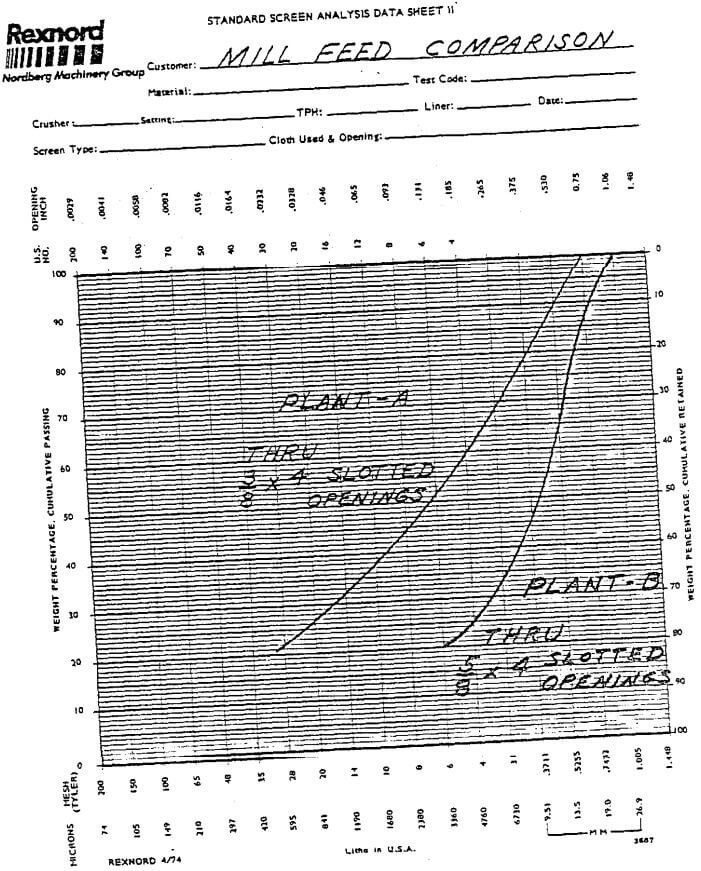
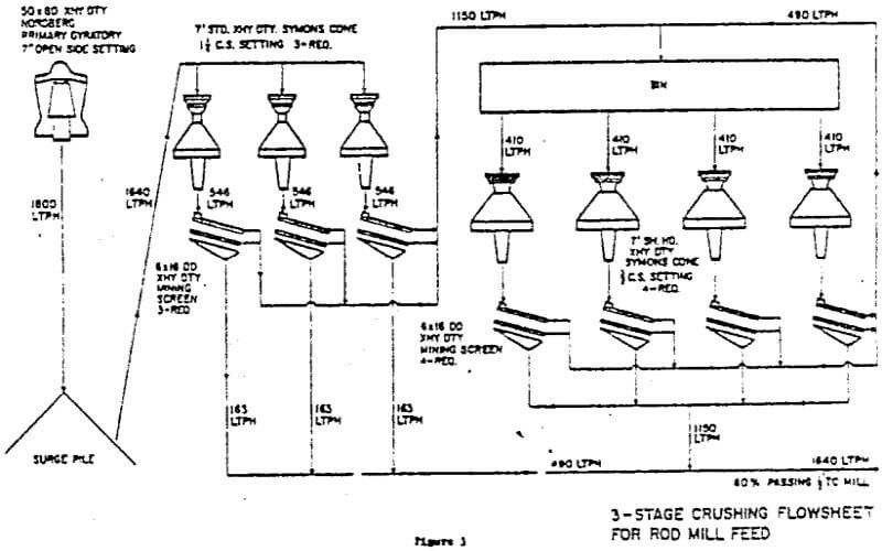
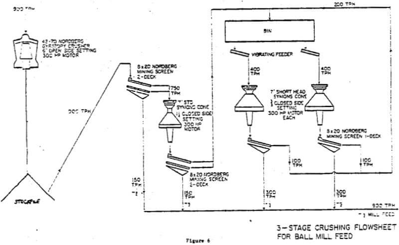
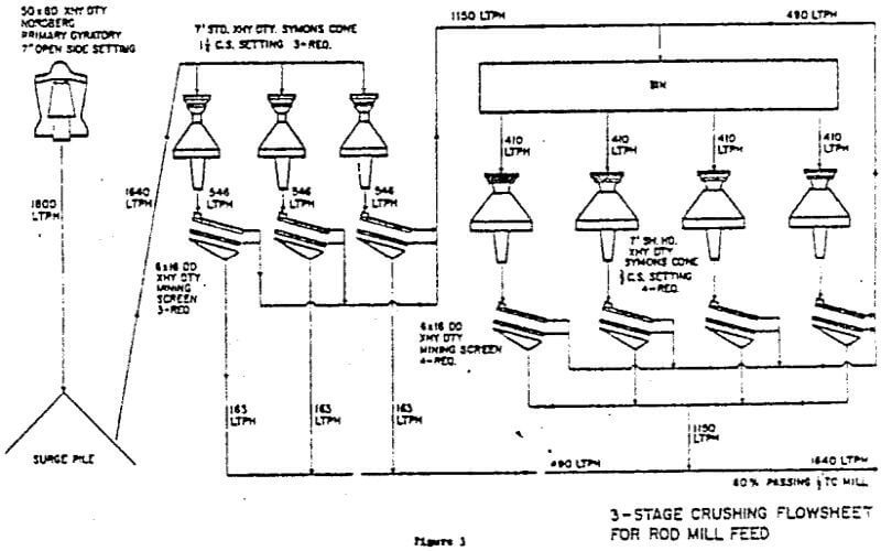
The trend in the design of fine crushing plants is in the direction of the horizontal arrangement with all crushers on a single floor. Conveyors from the coarse ore bin or stockpile, feed the scalping screens which are usually double decked. When the feed to the fine crushing plant contains less than 15 percent passing 19MM (¾ In.) and less than three percent moisture, the scalping screens ahead of the secondary crushers can be eliminated without adverse effects to the crusher.
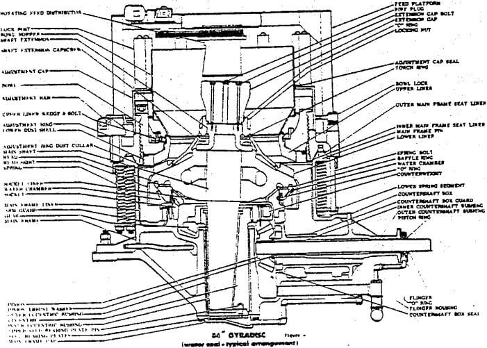
The use of hydraulic mechanisms for monitoring and controlling fine crusher settings from a central control room gives the operator a means for maintaining overall crushing plant efficiency. All that is needed for complete automatic control is the proper coupling of the power draft and volumetric controls of one stage of crushing to the positioning mechanisms of the preceding stage to insure the best balance between successive stages of crushing.
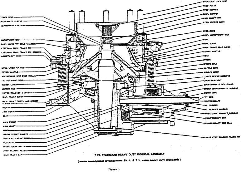
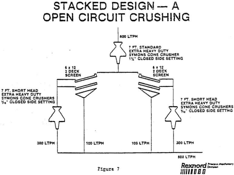
A) Stacked Design
- 1 — 7 Ft. Standard Symons Cone
- 2 — 7 Ft. Short Head Symons Cone
This design is intended to operate in open circuit. With fairly constant ore characteristics and where the feed to the fine crushing plant contains less than 15 percent minus 19MM (¾”) , screening ahead of Standard can be omitted. The Standard crusher closed side setting in this case is usually between 28MM and 37MM (1-1/8″ and 1½”) , Power requirements and maintenance are low due to the elimination of surge bins ahead of the Short Heads, closed circuiting conveyors and transfer points. The crushing plant product is controlled by the screens between the Standard and Short Head crushers and the closed side setting of the Short Head crushers. With this design it is a requirement to maintain a 6MM to 10MM (¼” to 3/8″) setting to produce a mill feed that is nominally minus 19MM (¾”).
The stacked arrangement is somewhat inflexible in relation to expansion, since a unit requires three crushers plus conveyor extensions. With the lack of adequate surge between the Standard and Short Heads, the degree of automation is limited; therefore, it becomes difficult to have all three crushers in the unit operating at maximum efficiency,
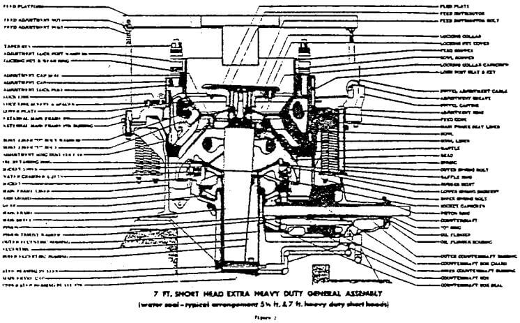
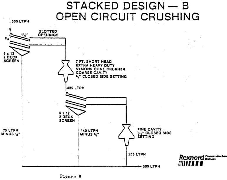
- 1 — 7 Ft. Short Head — Coarse Cavity
- 1—7 Ft. Short Head — Fine Cavity
This design is also an open circuit arrangement with some of the same limitations described in “A”, With two crushers in s unit or “line”, the automation is improved to a degree, but the lack of surge between the crushers prevents optimization of feed rate and power draw. Finer crushing is possible with this design since the closed side getting or the coarse Short Head is held to between 12MM and 15MM (½” and 5/8″) in comparison to the 28MM and 37MM (1-1/8″ and 1½”) setting on the Standard described in arrangement “A”.
B) Horizontal Arrangement (Open or Closed Circuit)
With this type of layout the location of crushing and screening equipment is quite similar with either open or closed circuit crushing. For closed circuiting crusher feed, larger or multiple vibrating screens are required ahead of the third stage crushing unit.
The advantages of this type of layout are:
- With relatively minor revisions, this plant can be expanded for larger capacities if suitable provision is made in the original design.
- Crane accessibility for maintenance of major equipment is good.
- The surge bin ahead of third-stage screening and crushing allows a short time lag for either manual or automated adjustment of crusher feed, resulting in high crusher productivity.
- During maintenance of individual units, only one crusher is down instead of three or two as required in the stacked arrangement.
C) Horizontal Arrangement (Closed Circuit)
This arrangement is similar to that in “B” except that all screening is done following the crushing stage permitting even greater feed rate and power control through automation. Flexibility in expansion, screen deck openings, and ease of maintenance are important advantages in this design.
D) Separate Fine Crushing and Screening Plant
This layout differs from others in that product from the second and third stage crushers is collected, conveyed, and distributed to the required number of screens in a separate screening section.
A significant advantage to this approach to fine crushing is that the necessity of matching screening units to crushing units is eliminated. When matching screening units to crushing units, the tendency is to undersize the screening units. The separate screening location minimizes the possibility of having the screens limit the fine product capability of the crushing plant. Since screening capacity can be easily expanded, the layout shown permits closer sizing of screening units to actual capacity requirements.
This layout allows for use of a standby screen or screens so that crushing operation is not affected by screen maintenance or changing of screen cloth. With any other of the arrangements shown, the cost of standby screens would be prohibitive. Screening requirements can change seasonally with moisture or as ore characteristics change with mine advance. Here, screens can be cut in and out of the circuit as required.
The layout is simple to expand. Crushers and screens are relatively close to grade, crane accessibility to equipment is good. Screens and crushers are basically at the same elevation allowing easy operator accessibility and inspection. Close instrumented control of crusher operation is possible.