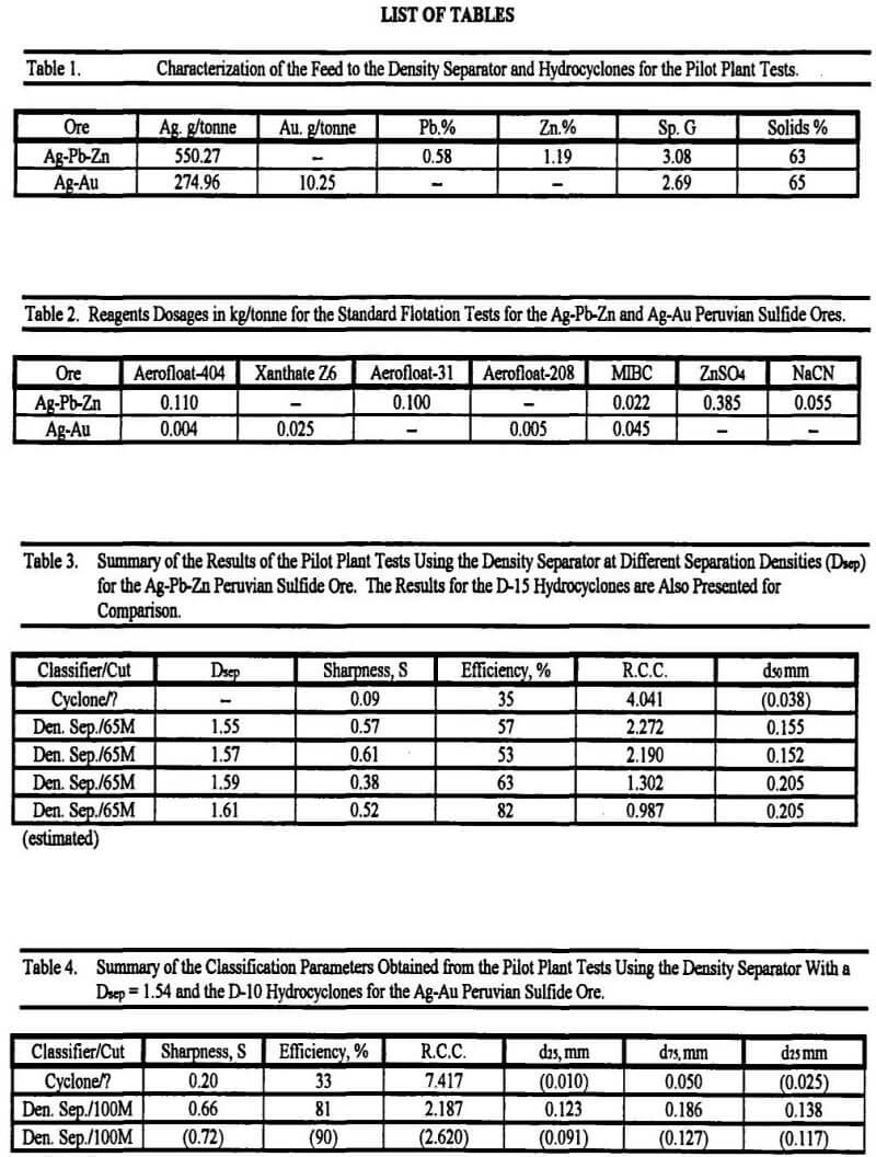
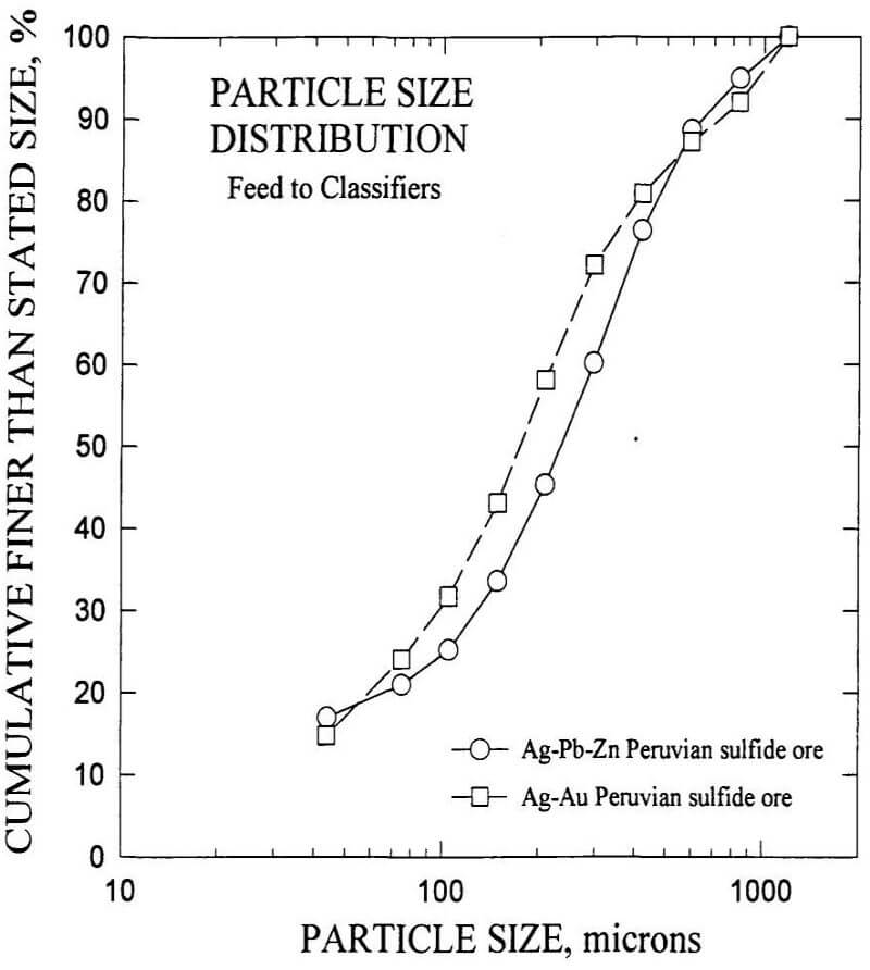
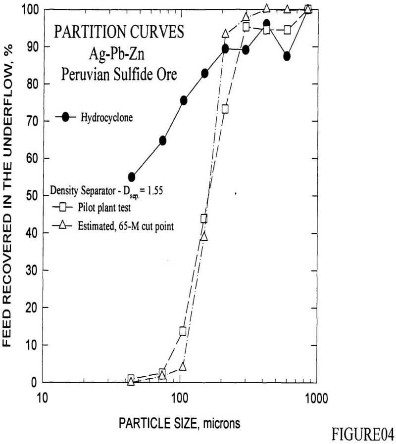
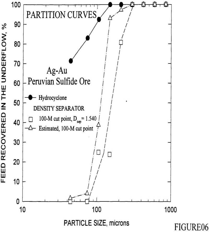
Ag-Pb-Zn and Ag-Au Peruvian sulfide ores were used for the pilot plant tests. For these tests, a stream of mineral slurry was directly obtained from the industrial grinding circuit to assure similar particle size distribution in the feed to both the Density Separator and the hydrocyclones. Table 1 presents the chemical analyses and specific gravity (Sp. G.) of the sulfide ores, and the solids content of the feed to the classifiers used in these studies, Figure 1 presents the particle size distribution for the Ag-Pb-Zn and Ag-Au sulfide ores. The d80 for the Ag-Pb- Zn sulfide is 0.420 mm, while that of the Ag-Au ore is 0.390 mm.
Pilot plant tests were conducted using a 381 x 381 mm Density Separator and D-15 hydrocyclones for the Ag-Pb-Zn sulfide ore, whereas a 152 x 152 mm Density Separator and D-10 hydrocyclones were used for the Ag-Au ore. The Density Separator is a hindered settling classifier with automatic control features that provides:
- Steady and sharp classification independent of extreme variations in dry tons per hour of feed solids up to the maximum designed throughput
- Flexibility of operation, allowing the change of the cut point while the machine is in operation to compensate for changes in the process variables.
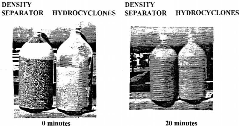
- Continuous overflow and consistent high percent solids (72-75%) in the underflow slurry.
- Data acquisition of the operating variables, which may be remotely indicated, recorded or monitored.
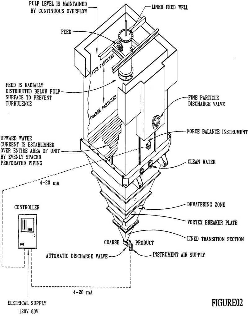
The Density Separator shown in Figure 2 consists of an upper parallel-walled section of square or rectangular cross section and a lower section consisting of one or more pyramidal discharge units. A rising current of clean water is established over the entire area of the upper section by the injection of a pre-determined flow of water through a series of horizontal, evenly-spaced, perforated pipes located at the junction of the upper and lower sections. These perforated pipes direct the water flow straight down. The mineral slurry is continuously fed to the upper section of the equipment through one or more feed wells, and the slurry is expanded in a teeter zone by the rising current of water. The particles are then classified, such that the coarser material reports to the bottom of the teetered mass while the progressively finer material is distributed in the upper portion. The pulp level is maintained by the continuous overflow of the unit. Both the interstitial water velocity and the specific gravity of the pulp progressively increase with depth from the top overflow weir to the bottom of the upper part of the unit. A force-balance pressure sensing device with transmitter is located in the wall of the upper section of the unit immediately above the piping for the rising current water. A proportional output signal is coupled to a pneumatically operated discharge valve with positioner through a process controller.
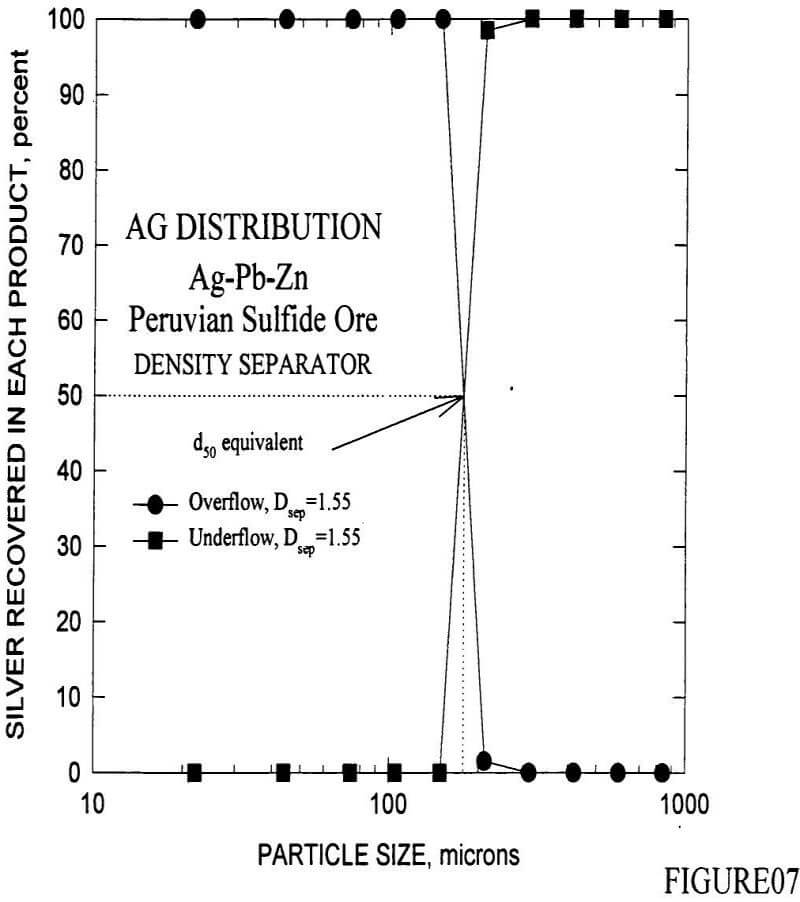
The pre-determined rising current of water is established according to the desired cut point (separation mesh) and the characteristics of the mineral suspension. For a given upward current of water, the specific gravity of the mineral suspension at the level of the force-balance instrument is indicative of the average particle size of the material above the instrument.
When the desired specific gravity of the pulp is set in the process controller, the discharge valve opens at the bottom of the unit when the specific gravity of the mineral suspension reaches that set in the process controller to maintain the equilibrium in the system and the set value. The underflow contains 72-75% solids, independent of the solids content in the feed. Once the rising current of water and the specific gravity of the pulp in the teeter zone are set, the mineral suspension becomes, in fact, “the primary operating part of the machine”.
Essential to the maintenance of the desired classification is a relatively constant volume feed rate to the Density Separator which is generally achieved in practice by feeding the circuit with a constant speed centrifugal pump operating with a constant suction head. Furthermore, the efficient operation of the Density Separator depends on the introduction of a constant rising current of water over the whole area of the tank. Thus, the water to be supplied should be at a constant pressure, clean and free of trash that could plug the water distribution system. To meet these criteria, the Density Separator is supplied with a modulating pressure reducing and regulating valve to maintain the discharge pressure within acceptable limits, non-return valves to prevent reverse flow and entry of solids into the rising current piping, and water flowmeters to measure the rising current water. In addition, it is essential to the operation of the Density Separator that the water supply be as clean as possible.
The particle size range in which the Density Separator obtains the best results is between 20 mesh (0.841 mm) and 325 mesh (0.044 mm) for feed rates between 18.2 tonnes/hr (20 Ton/hr) to 816 tonnes/hr (900 Ton/hr) for single machines.
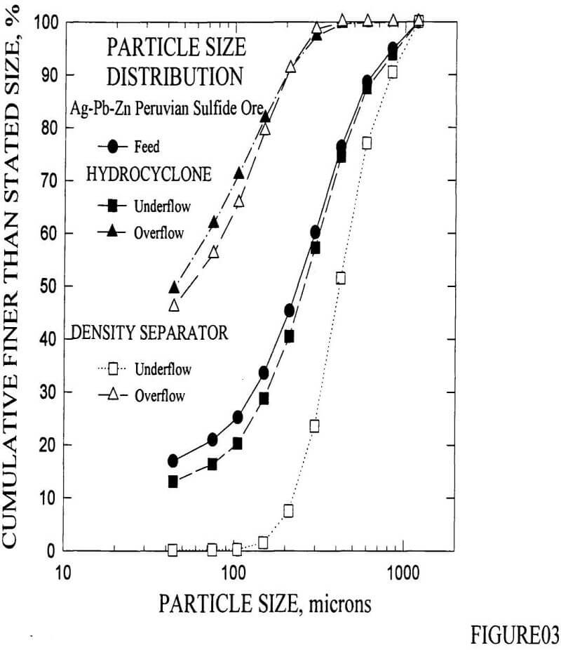
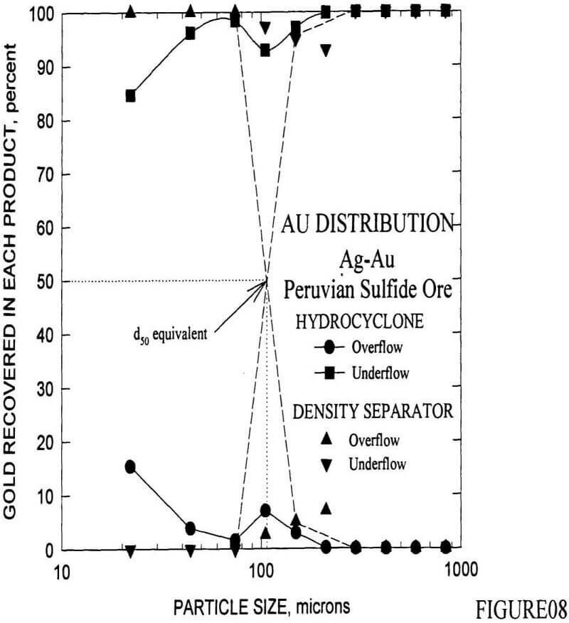
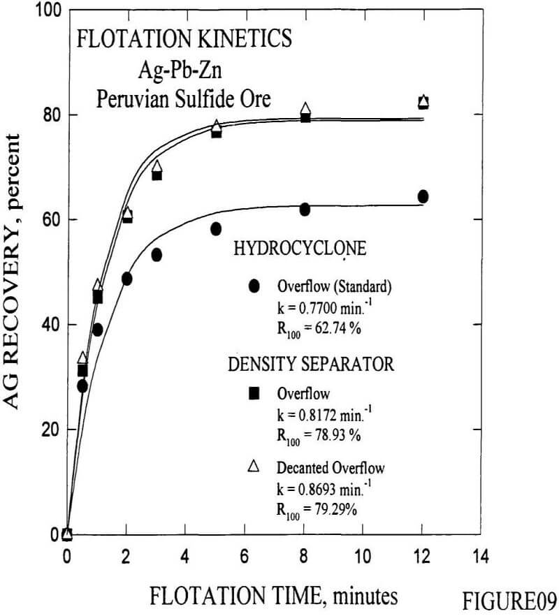
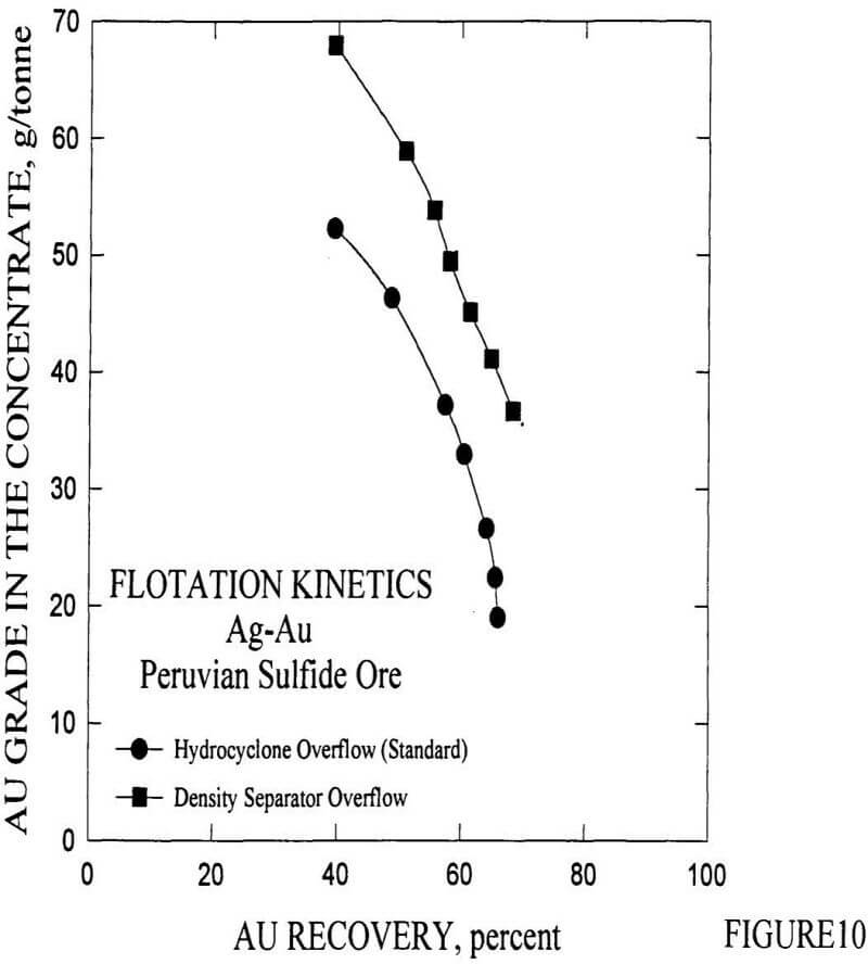
For the pilot plant tests for both Ag-Pb-Zn and Ag-Au sulfide ores, a stream of feed slurry from the operating hydrocyclones was fed to the Density Separator. In the case of the Ag-Pb-Zn ore, a 381 x 381 mm Density Separator was operated for four hours at different separation densities (Dsep). For the Ag-Au ore, a 152 x 152 mm Density Separator was operated for eight hours. For both pilot plant tests, samples were obtained every 10 minutes. Parallel to the Density Separators sampling, the operating hydrocyclones were evaluated. The feed and the classification products (overflow and underflow) for Density Separators and hydrocyclones were submitted to screen assays and the overflows to flotation tests in an Agitair No. 500 Laboratory Cell to evaluate the flotation kinetics. For these tests, standard flotation conditions for each mineral were used, which are presented in Table 2.