
The Metallurgy of Dredging: The gold-saving appliances of a dredge consist respectively of screens, tables, and sluices.
The essential duty of the screen is to classify the material prior to concentration, it also serves to disintegrate or break up the material passing over or through it, so that particles of gold may not be carried off in lumps of clay or cemented gravel, to be lost by passing out at the lower end over the stacker. The aim also, of course, is to prevent the larger gravel and boulders from being washed over the sluices. It is held by some authorities that the old fashioned single-lift dredge, where everything passed from the upper tumbler over long sluice-boxes with riffles supported on a pontoon behind the dredge, is of equal gold-saving efficiency and more economical (when properly designed and managed) than the present style. There are cases too where the double-lift dredge with the long sluice might be advantageously replaced by the single-lift pattern. As to the choice between the revolving trommel and the shaking screen, those who use the former claim that when constructed, as it usually is, with flanges and rods across it, it turns over lumps and exposes them to the action of the water-jets on all sides. On the contrary, those who advocate the shaking screen contend that the jets have a thinner surface to play upon, the actual screening is larger and the material is deposited on a wider surface. From the modern standpoint, however, the last consideration does not count for much.
The first cost and repairs of the revolving screen are usually greater than those of the shaking type. The diameter of the holes is governed by the size of the gold; as this is usually very fine throughout the Sacramento valley, the holes vary from 5/16 in. to ½ in. at the upper part of the screen and from ½ to 5/8 in. at the lower end. The holes are reamed on the outer side to give a free discharge. Anyone who has watched the action of either sort of screen for any length of time, particularly on boats where a sticky clay is treated, does not have to be told that neither of them is a thoroughly efficient machine for the work. Quantities of fine material may be seen passing to the stack-piles.
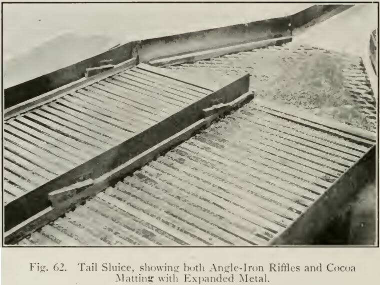
The patterns of the gold-saving tables and sluices differ widely. Formerly, on the Risdon boats, cocoa matting with expanded metal in diamond-mesh pattern was used, but this material has been almost exclusively replaced by riffles and quicksilver, but the designers still use the tables sloping toward each side of the boat at right angles to the slope of the screen. In boats of modern design various devices are used under the screens.
A certain proportion of the material delivered by the bucket over the upper tumbler does not go into the screen-hopper, being carried too far forward in its delivery. A grizzly is therefore arranged at the edge of the well; the undersize falls onto a short sluice with riffles (sometimes two are used, one under the other and sloping in opposite directions), which either empties directly into the well or (when sloping toward the stern) delivers into a pipe passing through the deck, or it may be carried down the entire length under the screen to the stern of the boat. On the Yuba boats where deep gravel is encountered and long ladders
are used, the tendency of the sag of the bucket-chain is to scrape against the edge of the well. An idler (a large flanged wheel or drum), is installed beneath the upper tumbler and serves to take up this sag. Although ‘save-all’ sluices have been placed on these boats, they are not of much service. In most cases on the Yuba the riffles are either banked with sand or carried away altogether by falling boulders from the overflow of the screen-
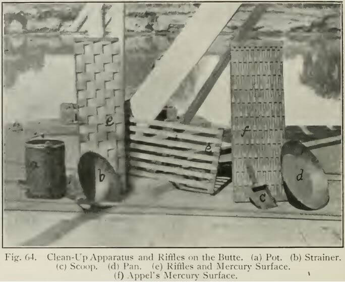
hopper. This is to be obviated by placing riffle-bars between the flanges of the idler-drum. Various gold-saving devices are used on the tables and sluices, but the angle-iron riffle is the most popular. This may be placed across the sluice-box or lengthwise, with small stones between the bars; a combination of these two is often used. Quicksilver, of course, is placed behind the riffles and at intervals, near the head of the tables there is a mercury trap of variable design. The best I saw and that giving the largest and cleanest surface was one designed by Mr. Harrison
Appel, at Oroville, and used on the Butte and El Oro dredges. It is made of wood with thin strips of metal on edge placed at intervals of ½ in. apart. Small blocks of wood keep the strips separate.
The chief value of cocoa matting is as a collector of fine gold, but the accumulation of sand and slime interferes, so that in the clean-up often only the coarse gold that settles behind the metal is recovered. It is a good idea to use a piece of this material near the foot of the plates, and indeed, some experiments are being made in this direction at the present time.
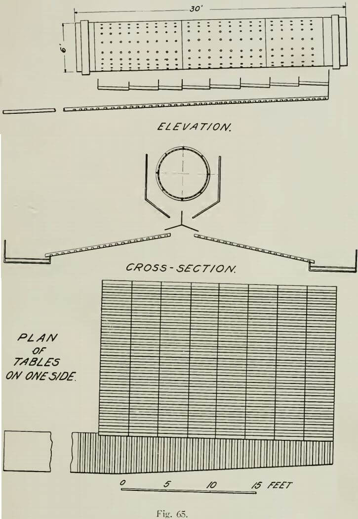
To illustrate some of the different screening and gold-saving arrangements on the various boats, the following specific cases are described by means of rough sketches. As an example of the simpler modern boat, the Yuba No. 4 has the arrangement shown in Fig. 65. Eight tables sloping at right angles to the revolving screen empty into a longitudinal sluice called the stream-down box; this is parallel to the screen. The tables and sluice are fitted with wooden riffles topped with iron hands, placed as shown in detail sketches. The bars are 1 in. high and 1 in. wide, and the spaces between are 1 in. wide; the tables are 30 in. wide and the ‘stream-down sluice’ is 18 in. wide at top. 4 ft. 3 in. wide at the tail and 30 ft. long. A plain iron sluice extension without riffles carries off the tailing.
A similar arrangement is used on the Boston & Californio No. 4 and other boats. More complicated schemes are employed on the Pennsylvania at Oroville, built by the Miners’ Iron Works, of San Francisco, and the Biggs No. 2 (now Exploration No. 2) built by the Bucyrus company. In the first case two flat shaking-screens are installed one over the other, with opposite motion. The upper screen has holes 36 in. diam., and the holes in the lower screen are 5/16 in. at the upper end and 3/8 in. at the lower. Under the lower screen are six layers of plank (ten in each of the two upper layers and nine in each of the others) placed across the direction of the slope of screens, at intervals, the layers sloping alternately forward and aft. These planks are grooved lengthwise with blocks placed in the grooves at intervals; they break joint in alternate grooves and are drawn out at clean-up. This forms a mercury trough. Under the layers of plank are ten tables sloping at right angles to slope of screens, each about 18 in. wide and fitted with amalgamating surfaces, planks are placed cross-wise with 1 in. diam. holes bored in them, cocoa matting, and cross-riffles. These empty into a ‘stream-down box’ with cross-riffles and end-riffles at
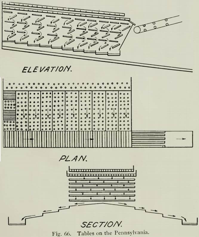
the lower sections. The side tables have two drops between the screen and stream-down sluice.
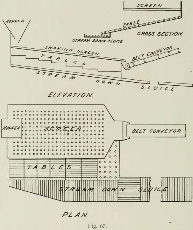
The Biggs No. 2 has a single shaking screen. Under this are two layers of plank placed cross-wise and extending about half way from the top of the screen toward the centre. The majority of these are fitted with small cross-riffles. Below (See Fig. 67) are the riffle tables and stream-down box, similar to those on the Yuba No. 4 (See Fig. 65).
On the Leggett No. 3, a Risdon boat built in 1904 at Oroville, the arrangement is somewhat different (See Fig. 68). A revolving trommel 54 in. diam. is used, built in four sections lengthwise. The total length of screening surface is 14 ft. The holes in the three upper sections are 3/8 in. diam. and the lower section has ½ in. holes. There is one row of square holes two inches around the top, to allow small stones to come through for filling riffle-spaces. The purpose of these stones is to protrude above the riffles and stir up the sand as it passes,
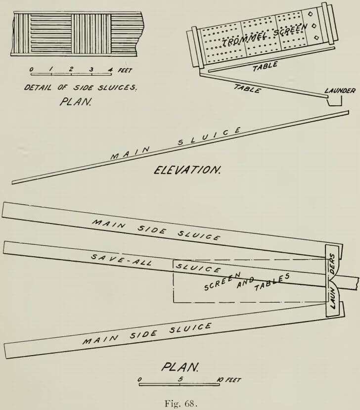
and they appear to take up natural positions in the riffles better than if placed there by hand. This allows the gold particles to sink into the quicksilver. The two tables under the screen feed to two launders, which deliver in turn to the main long sluices on each side and which, with the tables under the screen, are arranged with sections of angle-iron riffles, most of them placed end-ways, as shown in sketch. The save-all sluice extends from under the screen-launders to the stern of the boat under the screen-tables. The side sluices are now each 2 ft. wide and the save-all sluice is 18 in. wide. This method, however, is to be changed and simplified and, according to Mr. James Leggett, made much more efficient. The time of clean-up is to be shortened from one and one-half or two hours to half an hour. In the new arrangement, the save-all sluice extends from the grizzly to a point under the lower end of the screen, where it divides and passes out on each side of the stacker.
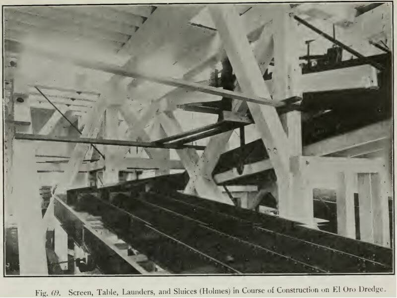
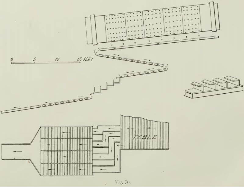
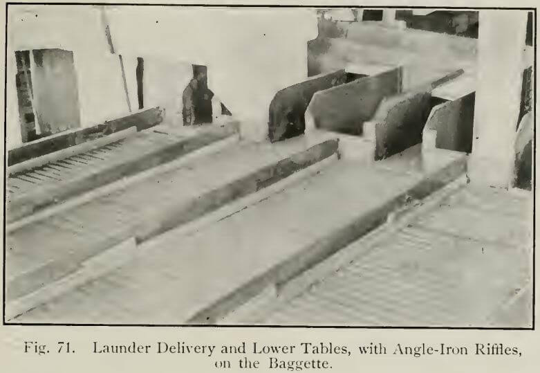
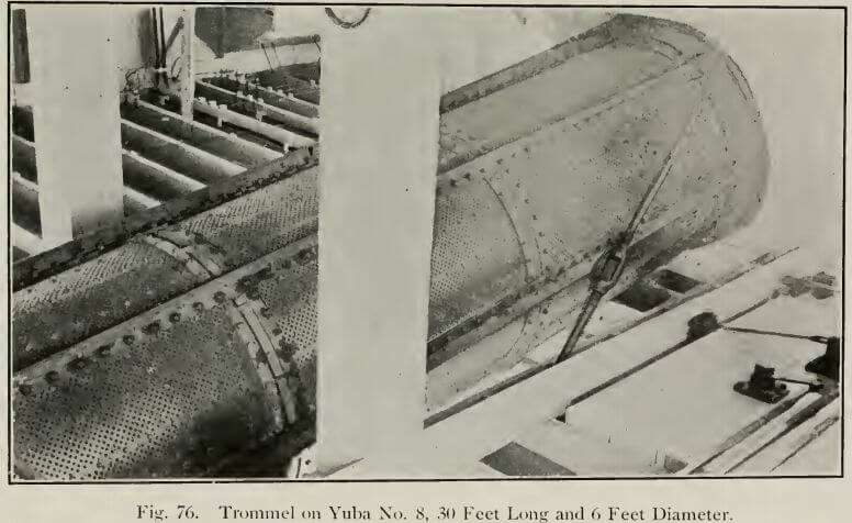
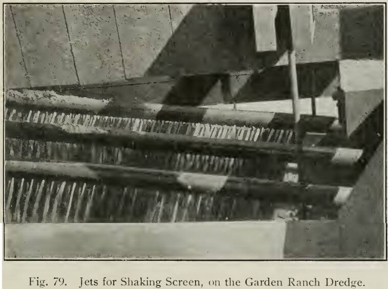
It is generally admitted that the Holmes system of launders and tables is the best gold-saving apparatus in use at the present day and it is already employed by many boats. They consist of a wide table or tray of iron plate directly under the screen and sloping in the same direction. This is either fitted with riffles or is a plain steel plate with sides. It receives the screening that empties from the end onto another plate, sloping in the opposite direction; this in turn delivers into launders (Fig. 69), which are divided, and empty onto a set of divided sluices sloping toward the stern of the boat on either side and fitted with riffles or other gold-saving apparatus. The launders and tables are generally of steel with steel bottoms, but sometimes they are partially constructed of wood. The following examples will illustrate the practical application of this form of table: In Fig. 70 is shown the arrangement employed on the Baggette, the latest and largest Risdon boat, the trommel screen is 29 ft. 6 in. long and 6 ft. diam. The screening surface is 21 ft. long; this length is divided into five sections. The holes in the two upper divisions are 5/16 in. diam. and in the three lower portions are 3/8 in. Directly underneath the screen is a plate 8 ft., as long as the screen and fitted with angle-rich cross-riffles. Two lower plates are also arranged with riffles. They empty into the launders as shown in Fig. 69. The launders are of iron plate, with double bottoms and deliver to the four sluices on each side, each 30 in. wide and 12 ft. long. The ‘save-all’ sluice is 30 in. wide by 28 ft. long.
On the Butte, the arrangement is slightly different. Two shaking screens are employed, the upper one 13 ft. long by 4 ft.
8¼ in. wide, and the lower one 13 ft. long by 5 ft. 7 in. wide and punctured with 3/8-in holes; the undersize is carried onto a steel tray divided lengthwise by three angle-irons and sloping with the screen. These irons prevent accumulation of sand when the boat
lists. From the lower end of this tray the flow is onto a riffle-plate, B, the same width, which in turn delivers into the launders, and thence to the sluice-plates.
The arrangements on El Oro are practically similar, with some slight change in the plan of tail-sluice.
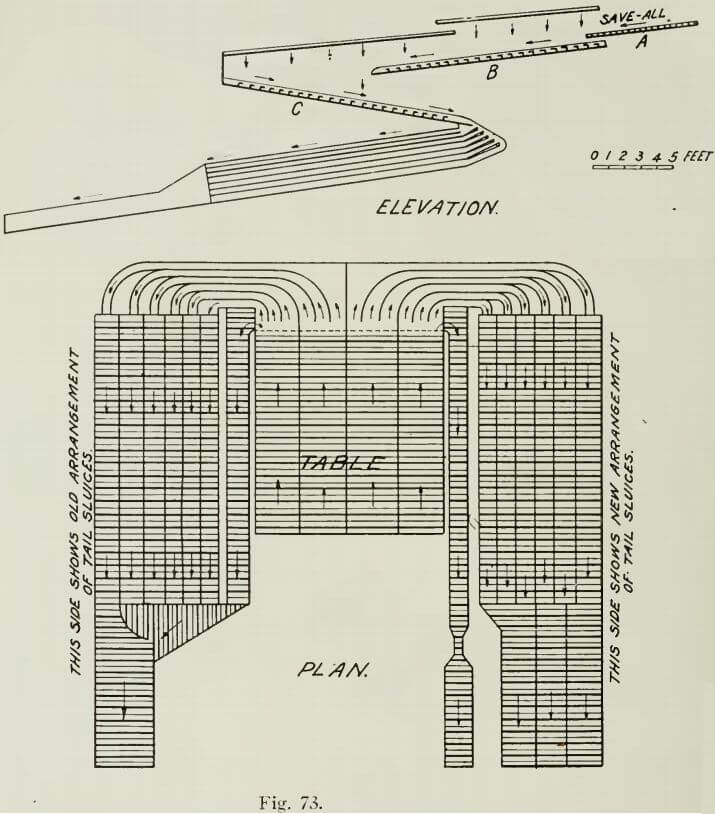
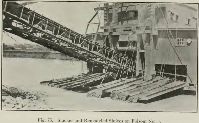
A brief description of the gold-saving apparatus on the Folsom No. 4 will be interesting, as it is the largest dredge in the world. Double shaking screens are used, the upper one 10 ft. 6 in. long by 11 ft. 11 in. wide and the lower one 14 ft. long by 12 ft. 8 in. wide. The save-all sluice A, (Fig. 73) is at such a height that it delivers onto plate B, under the upper shaking screen. Table B delivers onto C and C into the launders, which are curved
and drop in steps toward the outside of the boat corresponding to the steps in the sluices, of which there are seven, running lengthwise with the boat. Cross-riffles are used and stops are fitted at the points shown.
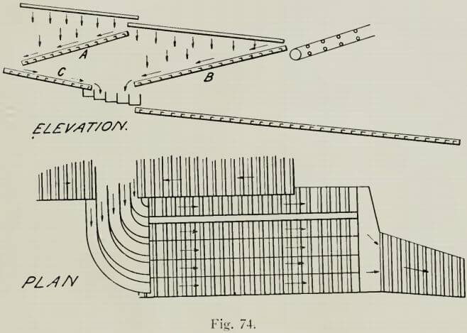
No. 5 boat at Folsom has a most interesting arrangement, recently installed. The screens are not changed; the dimensions are: Upper screen 16 ft. long by 11 ft. 10 in. wide; lower screen 16 ft. long by 8 ft. 9 in. wide. They were arranged originally as in Fig. 74. The undersize from the upper screen dropped onto table A and that from the lower onto table B. Table A delivered onto plate C, and C and B delivered into the launders, which were situated about midway under the screens. Plates A, B, and C were all riffled. The launders fed onto a series of Holmes tables, as shown in plan. In the new arrangement, table C is removed altogether. Table A receives the undersize from the upper screen and delivers to one set of launders and onto three tables, which have been raised up. Plate B delivers the undersize from the lower screen into a set of launders 4 ft. lower than the first set and these deliver in turn onto another and lower set of tables. Thus the product is divided and the separate clean-up becomes useful in testing.
On another boat belonging to this company, a grating (under-current) has been put in the sluice and part of the product is received on a separate sluice. Unfortunately not enough of such testing work is done on the dredges and the results usually leave the operator in the dark as to his losses.
The gold-saving efficiency of a dredge is affected by two factors that also influence stamp-mill practice. I refer to the grade of the tables and sluices, and the amount of water used. It is considered that 1½ in. per foot is the most efficient slope for the tables and sluices; the amount of water is variable. As a matter of fact, no arbitrary rule should be blindly applied. The slope and flow of water should be adjusted so that all of the gold will come in contact with the quicksilver. Impact, assisted by small ‘drops’ in the sluices and a break in the current are conducive to effective amalgamation. Too much water at too great a speed, however, may carry off fine gold, some of which in the Oroville deposits, is (to use a well-worn illustration) so fine as not to settle after two hours in a bottle containing a weak acid solution. On the other hand, if the grade is so flat or the volume of water so low as to allow an accumulation of sand to cover the mercury, amalgamation is hindered. The filling of the interstices of the cocoa matting by fine sand or slime is a drawback to that method of gold saving.
It often happens that the boat has a list according to the pull on side lines, and the sluices on one side may be seen banked with sand, while the riffles are covered. Almost every dredge has a variable ‘flotation’ level at either end, depending on the hardness of the ground being dredged, and the depth to which the ladder is digging. Due to this cause and the list, therefore,
it is seldom that the sluices and tables maintain the most favorable angle. In any case, the gold is so excessively fine, particularly at Oroville, that much of it is lost even under the most favorable conditions possible with the present gold-saving devices. The extent of this loss is not known, as the small amount of research work has given no results of any value. This is one of the features of dredging that surprises the millman and metallurgist. Even the technical mining engineer whose chief work lies among placers—and this is now recognized (particularly in the West) as one of the specialties of the profession—has little to offer in the way of authentic data regarding the actual contents of the ground that he may be exploiting and consequently he cannot know his losses. No proper testing of the tailing has been made; automatic sampling is unknown. Nevertheless, on being questioned, the manager will tell you that he has sampled his tailing and knows just what his losses are. On closer interrogation he says that he has made his conclusions by careful pan and rocker work at the tail-sluice and that what a pan or rocker will not save, no sluice or table will. At assays, he sneers.
Many mills built ten years ago are now known to have lost large sums in gold and silver that might have been recoverable how many mines are now, by improved appliances in the mill proper, by fine grinding, cyanide, chlorination, or other chemical or mechanical means, reducing ore at a profit that ten years ago was pronounced by engineers as ‘too low-grade’ to pay? Consider the comparatively recent improvements on the Rand, in Australia, and elsewhere in slime-separation and the consequent increased recovery. In some cases dividends are being paid entirely from this saving.
The dredge operator does not care what the ground may contain—by assay—so long as he is sure that with the present devices he is saving all that is commercially possible. At the same time he is open to consider any improved methods of saving you may offer and says, in effect, that when the process has been proved practicable, he will examine his ground (which will no doubt then be worked out) to see if it contains the value which your method may recover! Not very logical, to say the least of it. What would have been the present state of the industry if this had been the standpoint of miners since the days of which Pliny writes?
There is certainly a large loss, due to mechanical arrangements, in the material that passes over the upper tumbler and into the well. This is increased on the Yuba boats, where the idler arrangement makes it difficult to take proper advantage of the save-all. Even in boats without this idler, the loss in the well is known to be appreciable. It is not of much use to attempt to find an accurate method of testing the gravel in place before dredging, as the point to be decided is the absolute amount of gold that is actually passing through the dredge and being lost at the tail (including that which goes over the stacker), and all the gravel is not passed through the dredge.
Even the character of this gold is not known except that some of it is excessively fine. It is possible that a proportion of it is not only fine, but coated or otherwise unfit for amalgamation. ‘Rusty’ gold, so-called, due to a coating of silica and sesquioxide of iron is not at all amalgamate and what little of it is caught is due entirely to its specific gravity. The results of an interesting experiment conducted by Mr. Charles Helman, partly in my presence, are indicative of possibilities in the direction of such research. In the first place, however, it should be said that accurate automatic sampling must be applied over a proper period to get correct results. No dipping or digging of a haphazard sample from the tailing-bed will do, nor is the method of placing a tub at the end of the sluice efficient, for the tendency of the finest silt (probably the most valuable portion) is to flow off in the rush of water. In the case mentioned above, some of the muddy water collected carelessly from one or two buckets of the sand at a clean-up was filtered and the resultant impalpable reddish powder assayed $9600 per ton in gold and not only could not a ‘color’ be detected with the strongest glass but it was also found that none of it would amalgamate! This powder it is true, represented a certain amount of concentration, but it would stand a great deal of dilution, and still carry values that would make even a chemical method of treatment profitable. With dredges of the single-lift and long-sluice pattern the re-handling of this material would be facilitated. The finer portion of the tailing might be treated on the bank, if valuable enough.
An instance of testing the tailing at the Conrey placer mines at Alder Gulch, Montana, is of more than passing interest, most work of this description having been of a very perfunctory nature. Single-lift dredges with long sluices supported on a pontoon are used in this district and holes were drilled through the tailing behind the dredge with a Keystone machine. The material was found to be unproductive, with the exception of the bottom layer of 6 in. or 1 ft., where gold values were recovered that made an average of 4 to 6c. for the whole tailing mass.
An extract from one of the earlier reports of the California Bureau of Mines describes tests of muddy water from some of the best of the Grass Valley mills. In 12 tests, where water was taken from a point nearly a mile below the mills, returns were obtained by assay of about $2 per ton. It was estimated that 576,000 gal. of this water flowed every 24 hours, which meant $339 of float gold, to say nothing of loss by imperfect pulverization. A clean-up of the twentieth undercurrent of the Spring Valley Hydraulic Co., at Cherokee, Butte County, Cal. yielded $2600. This gold was taken from material that had been sluiced over 2½ miles of sluices and over 19 other undercurrents, and even then Chinese were working the tailing below this point; moreover, the gold-saving system of this company was supposed to be the most complete in the State, so that it may be easily seen how loss occurs over the short-sluice system of a dredge.
The clean-up is made at intervals that vary on the different dredges, as also the time it takes to accomplish it. As extraction ceases during the clean-up, it is important that it should not be done oftener than is necessary to prevent loss by overloading the tables and sluices. In some cases certain tables are shut off from the screen-delivery, the flow being allowed to continue over the others; in this case digging is not interrupted. It is doubtful, however, if this is good practice. In other cases, the two sides are cleaned up on alternate days, digging continuing all the time. Usually a special set of men is kept for this purpose where several boats are in operation. On the Yuba until recently there were six boats operated by one company and in each case one day was devoted to the clean-up. This work is done by three
men who also measure the bank, do surveying and other work, and when necessary, call on the boat’s crew for assistance. One of the party attends to the melting. In this way the men become expert and time is saved. The enforced idleness during clean-up time is employed in making repairs, oiling, etc. Of course, in the case of a company with only one or two boats, it would not be practicable to employ a special clean-up crew.
To illustrate the most general practice in cleaning up, a description of the process on Yuba No. 4 is given. A revolving trommel delivers onto eight tables on each side and these empty into a stream-down sluice (See Fig. 65). All of the tables are fitted with wooden riffles capped with a flat iron band. These are 1 in. square in section and placed 1¼ in- apart. The side tables are 30 in. wide and 13 ft. long, and are fitted with two stops or permanent bars, one at centre and one at the lower end. The stream-down sluice is 18 in. wide at the upper end, 4 ft. 3 in. wide at the lower end and 30 ft. long. The clean-up is done on both sides of the boat at the same time, by the clean-up force assisted by the regular crew. The screen-motor is stopped and, of course, digging ceases. Two men loosen up the riffles on the upper side- table with a bar and these are washed onto the table with a hose and laid aside. The hose is then used—always pointed up-sluice to wash down the coarse gravel—and each man taking a section above the stops, stirs the material with a small rake, something like a currycomb, so that the coarse material passes over the stop. The amalgam, quicksilver, and black sand remain behind the stops; the clean-up men pass onto the next table, and so on, until all of the side-tables are finished in the same manner. Meanwhile two other men with buckets and a wooden hand-trowel scrape the material—amalgam, quicksilver, and black sand—into the buckets, which are then emptied into a wooden tank that is kept full of water. When the tables have been finished, the water is removed from the tank (with a basin) and the material is lifted (with a scoop) and carefully fed into the hopper of a ‘long tom’ constructed as shown in Fig. 77. This sluice is 14 ft. long and the width inside the box is 12½ inches.
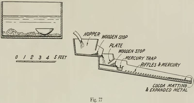
Water is fed into the hopper by a hose from the pump. The mercury trap is kept stirred with a long spike and 90% of the amalgam is caught above the stop B just above the mercury trap. The amalgam is removed from the sluice and drained in a small inclined metal trough and the ‘quick’ is collected from the trap in the long tom and strained. The sand from the side-tables is put back into the vat and passed through the ‘tom’ again with the material collected from the stream-down sluice. The amalgam and mercury are thus collected, while the sand remaining at the end of the process is replaced on the sluices. A ‘long tom’ is used on each side of the boat and the results from the side-tables are mixed together for retorting and melting, as is the material from the stream-down sluices on each side. The trommel rotates from starboard to port, like the hands of a clock and the material is usually thrown up on the port side of the screen, but with the side-tables the screen-delivery is arranged so that most of it goes to the starboard tables and most of the gold is caught on this side. The clean-up commences at 7 a. m. and is completed in from 2 to 3 hr. Minor repairs are usually done at this time and the boat is ready to continue digging about noon. Cleaning up was formerly done once in every six days but the two new boats (No. 7 and 8) being now completed, it will be done once in eight days.
The clean-up on the Leggett No. 3 is done differently. The arrangements of the screen and the sluices have been previously explained. The riffles on the upper table are first removed and washed onto the screen, while a full head of water is turned on. The sand and mercury are carried down, the amalgam being retained behind a loose stop. The upper half of the riffles on the second table are taken up and washed and then the lower portion is treated in the same way, one side of the launder being stopped previously, so that everything is carried over one side-sluice. The lower sluices and the ‘save-all’ are then cleaned up. The whole process only takes about one hour and with the new system of tables it will take even less time. The essential difference from the ordinary method is that the head of water employed while digging is in use throughout the process. The clean-up takes place every ten days and mercury is fed onto the tables and sluices three times between each clean-up. The only boats now using
the amalgamating machine in cleaning-up are the Butte and El Oro, and the method as practiced on these boats, though thorough, is slow.
The processes being practically alike, one description will suffice. Each boat has shaking screens with a table underneath with the same slope as the screens and a second underneath the first, sloping back toward the bow and emptying into the launders. Each has a triple divided sluice-way sloping toward the stern, the tail-sluice on the Butte being arranged a little differently from the El Oro sluice, the riffles of the former being continued a little farther aft. The save-all sluice on the Butte discharges into the well of the boat, while the El Oro save all sluice slopes toward the stern and delivers the tailing into a pipe running through the hull. The clean-up, as in all cases, commences at the upper tables first and follows down to the tail.
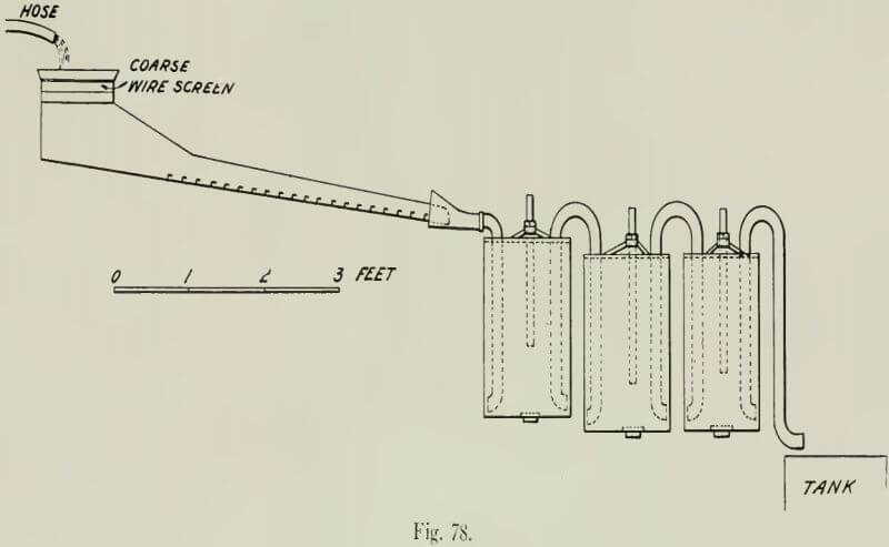
The slats on each side of the tables are lifted, by removing the wedges, and the sections of riffles are carefully taken out so as not to spill the ‘quick’ and amalgam that they contain. Then the bottom of the riffle-sections are tapped, scraped, and brushed into a trough, the top sections being done first. The material from this trough and the sand from the tables (from which the riffles have been removed) are conveyed by a couple of Chinamen with pots holding about two quarts, to the miniature ‘long tom’ (See Fig. 78). In the top of this, as will be seen, is a hopper with a coarse wire screen that may be lifted out and on which the material from the pots is hand-sifted. A hose from the pump is turned into the hopper. Below is a small set of riffles about 15 in. long and 12 in. wide, the overflow from which goes into a ‘Lasswell’s Fine Gold Amalgamator’. This consists of three iron pots 1 ft. 3 in. diam. and 1 ft. 8 in. deep arranged at intervals of 1½ in. apart, the first pot set on a level higher than the other two. The three are connected by syphon tubes bent into a short elbow at the bottom to give rotary movement to the water and sand, allowing the heavy material to settle. The tops are firmly closed, an air-pipe being inserted in each. A vent in the bottom is closed with a nut. The water, sand, quicksilver, and some amalgam passing over the little tom sluice, go through the series of three pots, the mercury and remaining amalgam being deposited in the first. The material is carried into a tank, which overflows into a launder discharging overboard. The ‘quick’ is drawn off at the bottoms and, later, the tops are taken off and the amalgam is removed. To show the efficiency , of the process, the contents of the vat, the result from a month’s run of some 40,000 cu. yd., was put through the process a second time and only a little over a desert-spoonful of quicksilver was secured, and this contained very little gold. The material in this vat is replaced near the head of the tables when the riffles are again in place. On the Butte the tail-sluices are fitted with one or two sections of cocoa matting, which are rinsed
thoroughly in water and replaced, the material deposited in the water being treated with the rest of the clean-up sand. About 50% of the amalgam recovered is found on the riffles in the small clean-up sluice or on the wire screen in the hopper. The contents of each table and the save all sluice are taken separately and the percentage separately calculated. The results show about 80 to 85% of the recovery from the upper table, 12 to 15% from the lower sluice-tables, and 2 to 3% from the ‘save-all’. The last product varies greatly in proportion. On these two boats the clean-up takes place only once per month. From 300 to 400 lb. mercury is put on the table, and sluices after each clean-up, and another like quantity luring the month. The resultant material from the clean-up consists of amalgam, quicksilver, sand, and small gravel. The cleanest of the amalgam is skimmed, strained through stout cotton cloth, and the quicksilver is used again on the tables, while the amalgam is placed in a metal funnel with a very small hole at the lower end, to drain off the mercury. The sandy portion of the clean-up is panned first over one tub to free it from the coarsest pebbles and practically worthless material, and then over a second. The amalgam and quicksilver are poured off and treated as before, the sand being kept separate.
There are now two products for the melting room: 1. Amalgam with a small excess of mercury; 2. Black sand containing lead, nails, etc. In most of the older districts, particularly those that have yielded large returns in the old gravel-washing days, the material now being dredged contains a large percentage of metal in the form of Chinese and other coins, small ornaments, buttons, nails, and notably lead in the form of shot and bullets, etc. Some of this material is contained in the second product. Much, however, must pass entirely over the tables, acting as a sluice-robber; thus, nearly every dredge has its proportion of lead bullion to be treated after the clean-up, every few months, for this material all collects some amalgam. With the black sand too, are collected traces of platinum, osmium, iridium, and possibly other rare metals. These do not amalgamate in the ordinary way, and it is quite possible that a comparatively large amount passes over the sluices and is lost.
But to return to the melting room: The amalgam, forming the first product, after careful weighing of each portion separately, is placed in an iron vessel and retorted in the furnace. The crude gold from the retort is in its original ‘plate’ or ‘scale’ form, though still containing enough mercury to make it adhere in lumps. It is placed with a flux of sodium bicarbonate and borax in a graphite crucible (previously carefully annealed) and smelted in the usual manner. It is then poured into the iron mold, coated inside with the smoke of burning rosin to give the bar a good surface.
The mercury from the dredge is cleaned at intervals, particularly when the boat is idle, by retorting, and leaves a white dross-like looking residue, which carries $16 per ounce in gold; this is very brittle, possibly by reason of the presence of antimony. In a recent retorting of 963 lb. of mercury, 55.5 oz. of this alloy was produced. It is sometimes melted with the bar and imparts a whitish color to the gold. The second product is screened, to separate the shot and nails, etc. and to eliminate the magnetic sand, the former material being placed in a clean-up barrel with water and iron rollers, and rotated. After this cleaning, the nails and iron are removed with a magnet and thrown away, while the residue, including the lead, is retorted to drive off the mercury. The lead matter that is produced is then smelted with flux and the resultant base bullion is worth $1.25 to $1.50 per oz. This is shipped to the Selby smelter with the gold. The black sand that is saved varies in value; that from the El Oro and the Butte for some six months averaged $140 per ton. Great quantities, of course, go over the tables; no special effort, in fact being made to save it. At Folsom the system is similar to that described on the Yuba No. 4. A vat and tom sluice are used and the sandy material from the tom is put through the vat a second time.
With regard to the value of the ground in the different districts, this varies greatly in the same locality, and most of the drilling tests disclose the fact that the highest returns are obtained from channels and patches (probably old river bars), but in dredging a tract the results of the drilling must be averaged to obtain the value of the whole area, which is, as a rule, all moved. For instance, if a rectangular area of 100 acres is intersected by two or three irregular and winding channels with ‘islands’ between and the values are, on the average, 25c. per yd. in the channels and 8c. per yd. elsewhere over the tract, and the cost of dredging is 6c. per yd., then, though to dredge only the low-grade ground outside the channels would probably not yield a profitable rate of interest, it might be found advisable to dredge the whole tract systematically rather than follow the irregular channels and rich patches even, if when lumped together they formed a fairly large proportion of the whole area. Such questions as these, however, occur constantly to the dredging engineer and must be treated separately and weighed strictly from a business point of view. The vital and only question to be decided is, whether at the completion of dredging a tract of auriferous alluvial land, the operator will have made the maximum amount of profit possible, giving the important factors of time and interest due consideration. As regards the prospect values of dredging ground and the recovery percentages therefrom, in these three districts, reference to the chapter on ‘Prospecting’ will provide actual cases.