Table of Contents
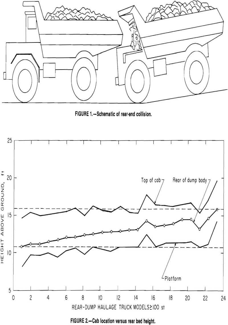
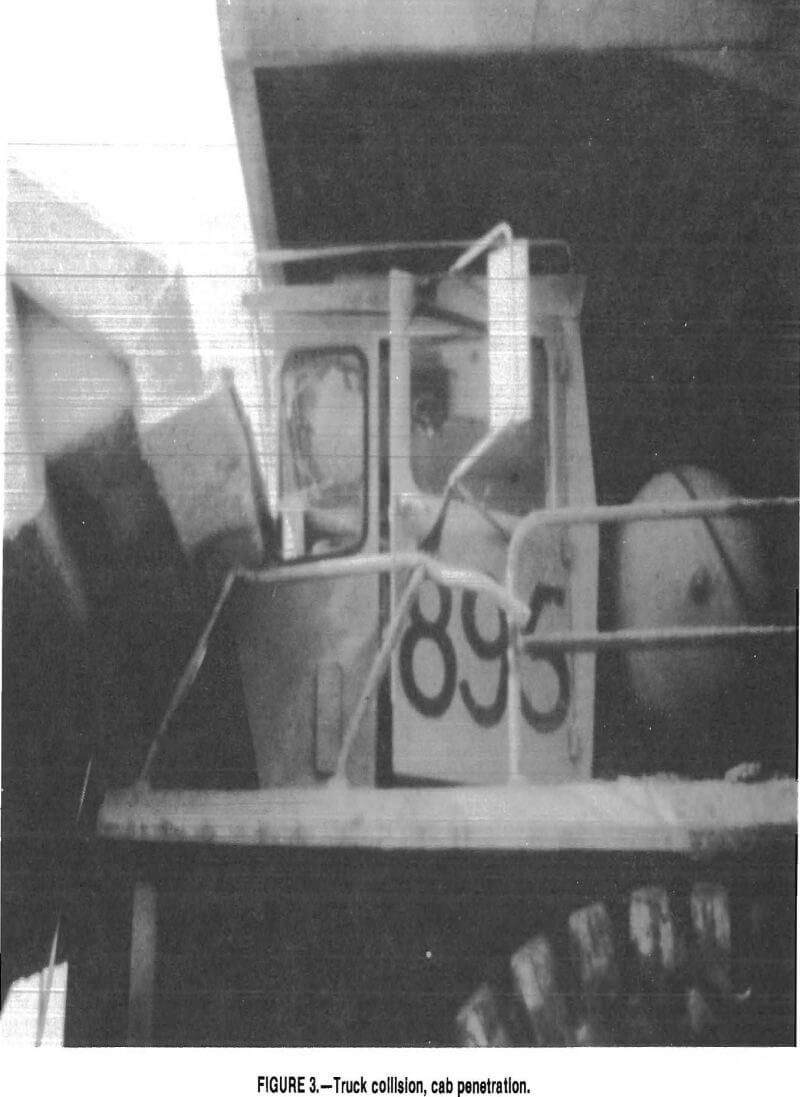
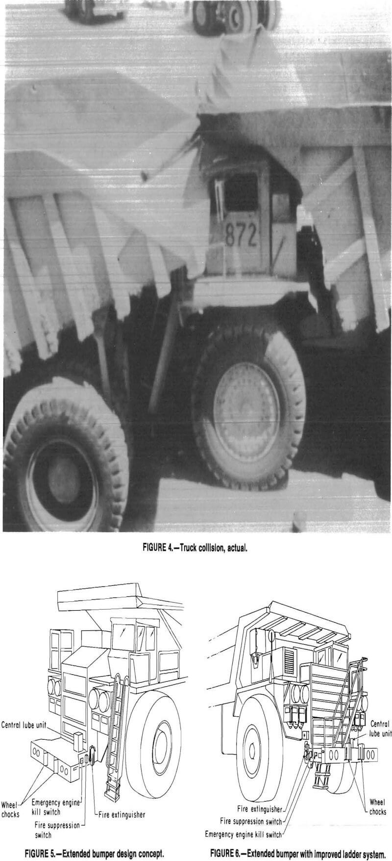
The extended Haulage Truck bumper was developed to provide protection to the operator in the event of a rear-end collision between trucks. This protection is necessary because the outcome of a rear-end collision between trucks often results in the rear-end of the dump body of the forward truck penetrating the cab area of the rearward truck (fig. 1), causing operator injury, as well as extensive machine damage. Figure 2 shows the relationship of the height of the rear of the dump body in relation to the top of the cab and operator’s platform for various truck models. This indicates that for most truck combinations, the height of the dump body is at a level to penetrate the cab area. Figures 3 and 4 show the results of truck collisions in which the dump bed penetrated the cab area of another truck, in each case, causing serious injury to the operator and major truck damage. The goal of this program was to design a bumper extending far enough in front of the existing bumper to prevent any intrusion of a dump bed of one truck into the operator’s cab of another truck during a collision.
To achieve this goal, one solution was to design an energy-absorbing system, similar to an automotive bumper system. This approach would be acceptable, but
would necessitate extensive laboratory testing to design and refine the system. Therefore, the approach used was to design a bumper long enough to prevent any intrusion into the cab area, wide enough to impact a minimum of two rear tires, and high enough above the ground to impact near the centerline of the tires. The bumper had to be designed to structurally carry the impact loads, with the energy being absorbed by the rear tires of the contact vehicle.
The bumper installation depicted in figure 5 is typical of extended bumpers presently in use. The bumper is equipped with headlights, clearance lights, wheel chocks, and an automatic engine kill switch; a fire extinguisher and a fire suppression switch are located near the ladder for use in emergencies.
Previous research had identified truck ladders both as having high maintenance costs and as a major cause of injuries. One method for reducing these injuries would be to install a staircase-type ladder on the front of the truck. This would normally result in increased maintenance requirements since this type of ladder would be more susceptible to damage; but with an extended bumper, a staircase ladder could be installed, as in figure 6, without increasing the
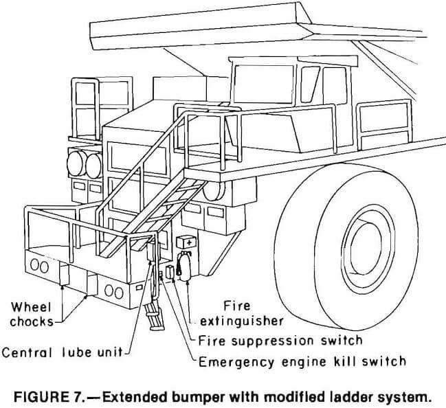
maintenance requirements. In fact, the maintenance requirements may be reduced when compared with requirements of a conventional ladder, which is outside the zone protected by the bumper. One problem with the staircase ladder is that anyone climbing up the ladder is not visible to the operator (fig. 6). With the extended bumper this problem can be eliminated, as illustrated in figure 7, since anyone getting on the truck steps upon the bumper from the driver’s side of the truck and traverses the front of the bumper in order to go up the staircase ladder.
This study was performed by Woodward Associates, Inc., San Diego, CA, under a Bureau of Mines research and development contract.
Critical Physical Dimensions
In order to ensure that the bumper meets the basic criteria of impacting the rear tires of a truck and preventing the dump bed from penetrating the cab area, it was necessary to determine the physi¬cal dimensions of the truck and bumper.
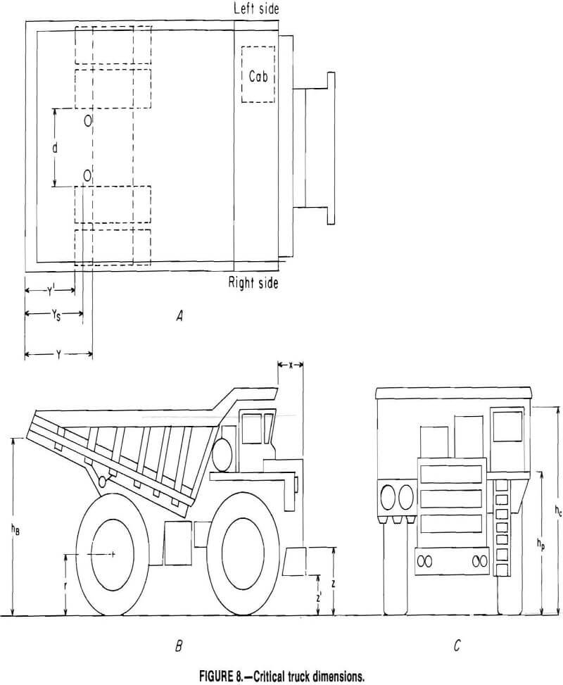
As shown in figure 1, the rear-end of the dump body for most haulage trucks over 100 st is at a height that would impact the cab on another truck. Therefore, it was necessary to obtain the physical dimensions to ensure the criteria were met. These dimensions included (fig. 8):
x = distance from the existing bumper to cab,
y’ = distance from rear tire to end of dump body,
r = loaded tire radius,
z = height to top of existing bumper,
z’ = height to bottom of existing bumper,
and
d = distance between inner rear wheels.
These dimensions were used to determine the following extended bumper configuration:
Overall extended bumper length, L, is defined by L > (y’ + tire deflection + bumper deflection) – x.
The overall extended bumper width, W, to impact two rear tires is defined by W > d + 2 (tire width).
The height of the bumper, H, should be H = r.
Since one of the requirements was to minimize damage to the extended bumper during impact, it was necessary to determine the tire deflection available for 170-st-capacity haul trucks before any suspension component is impacted. The WABCO, Unit Rig, and Euclid trucks have 18 in of tire deflection available to absorb the impact energy before a suspension component would be impacted. However, the Terex 170-st-capacity haulage truck has suspension components rearward of the rear tires. Therefore, the
bumper designs may not be effective when impacting a Terex truck.
The dimensions of the extended bumper and for 170-st trucks are as follows:
L = 4 ft,
W = 13 ft,
H = 4.5 to 5.5 ft.
Dynamics of Rear-End Collisions
For the purpose of analysis, three different impact configurations were considered for the design of an extended bumper. These cases were chosen to ensure structural integrity for a wide range of loading conditions:
Case 1: Direct rear-end collision.—The longitudinal centerlines of the two trucks are in line, resulting in a symmetric end loading of the bumper. The extended bumper impacts the inner left and right rear tires.
Case 2: Offset rear-end collision.— The extended bumper impacts one set of dual rear wheels.
Case 3: Angle impact.—One tire is impacted by one corner of the extended bumper, causing a side load on the bumper as well as a front and vertical load.
A dynamic analysis was conducted to determine the load magnitudes for the three impact conditions. Since most impacts are relatively low speed, the impact loads on an extended bumper were determined as follows:
Case 1—Impact velocity = 5 mph.
Case 2—Impact velocity = 5 mph.
Case 3—Impact velocity = 3 mph.
Another factor that influenced the assumed speed at impact was that the extended bumper must be weaker than the truck frames in order to minimize frame damage; the velocity for case 3 is lower since the bumper may only impact one tire, limiting the amount of impact energy absorbed.
Design for high-speed collisions will substantially increase the bumper weight, resulting in potential frame fatigue damage. A sensitivity analysis is needed to determine the optimum tradeoff point of bumper weight versus frame damage from both frame fatigue and ultimate strength standpoints.
The dynamic analysis assumes the worst case of two of the heaviest 170-st- capacity trucks impacting when both are fully loaded. The following is a summary of the factors included in the dynamic analysis:
Truck weights of 575,000 lb each.
Rotational inertia, 15 pct.
Actual load deflection characteristics of tires used on 170-st-capacity haulage trucks (36 by 51 type E-3 or E-4).
Assumed tire pressure of 75 psi.
Conservative value for a road adhesion coefficient (0.85), resulting in higher bumper forces before a machine may slide on the ground.
Truck frame capability.
Impact velocity (3-5 mph).
The analysis results in the following governing impact loads for extended bumpers in the three loading cases, in pounds:
Cases 1 and 2:
Front load……………………………………………………………………..640,000
Vertical load……………………………………………………………………38,400
Case 3:
Front load………………………………………………………………….280,000
Vertical load…………………………………………………………………16,800
Side load………………………………………………………………………75,000
Design Criteria
There are two primary causes of rear-end collisions between haulage trucks: (1) loss of control and (2) poor visibility or not seeing the other truck and therefore backing into it. Collisions resulting from these two causes have different characteristics with regard to the type of protection required to prevent penetration of the dump body into the cab.
The loss of control accidents are the result of mechanical failure in either the retarding or braking system. Therefore, the collisions may involve a substantial speed differential between the two trucks. This type of collision usually results in large amounts of tire deflection; the bumper must extend far enough forward to prevent the dump body from entering the cab with the maximum amount of tire deflection.
The poor visibility accidents are usually low speed (under 3 mph) and occur while the truck is maneuvering in congested areas, such as near shovel or dump sites. These collisions create another bumper design problem, in that quite often two trucks are at an angle to each other. It would not be practical to have a bumper that would eliminate all of the hazards from this type of collision, because the bumper would have to be wider than the truck. In addition, this type of collision also produces significant side loads that the bumper must withstand.
It is important to note that the amount of protection provided by any given
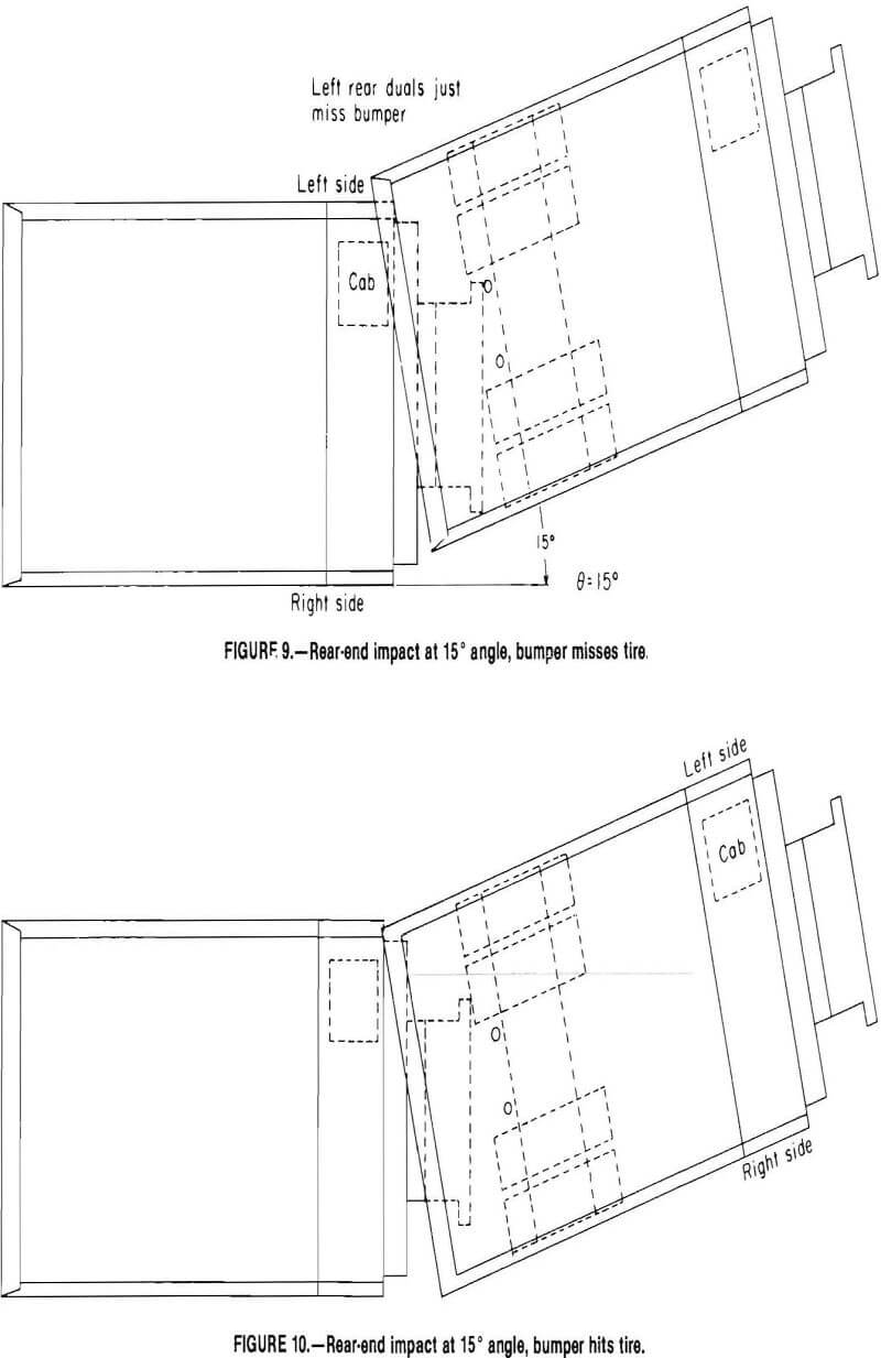
bumper is dependent on the angle between the trucks and the way in which the rear tires hit the bumper. As illustrated in figure 9, a collision in which the left rear wheels just miss the bumper can allow the dump body to hit the cab. However, if the bumper hits the left tire, the dump body would miss the cab (fig. 10).
Collision Dynamics
The maximum strength of any bumper is limited by the strength of the frame. However, the bumper must be sufficiently strong to survive a collision between two trucks at a given speed. While the analysis of the forces generated in a collision between two trucks is extremely complex, certain assumptions can be made in order to determine the maximum forces an extended bumper must support. These assumptions include the following:
The truck frame is rigid and the bumper will fail before the frame is bent.
The bumper will only make contact on the rear tires of the other truck.
All of the energy is either absorbed by the tires or dissipated by moving the other truck.
The rotating inertia due to the mass of the rotating components of a moving truck is 15 pct of its kinetic energy.
In addition to these assumptions, there are several critical factors that must be determined in order to analyze the bumper loads including the following:
K = deflection rate of the tires,
U = the road adhesion coefficient between the trucks tires and the ground,
X max = the maximum deflection of the tires before a solid part of the truck is impacted,
N = number of tires impacted,
and
∅ = angle of impact between the trucks.
Since most 170 -st-capacity trucks are equipped with 36- by 51-in type E-3 or E-4 tires, the load deflection rate for a given tire is dependent on the manufacturer, type of construction, and the air pressure. However, since these tires must be able to support the same load without overheating, the load deflection rates of the various tires are similar. As shown in figure 11, the load-deflection curve for a typical 36- by 51-in tire, the rate is a linear function highly dependent on air pressure. The effect on the bumper design is to increase the forces as air pressure is increased and the tire becomes harder. If the air pressure is low enough to cause the bumper to strike the rear
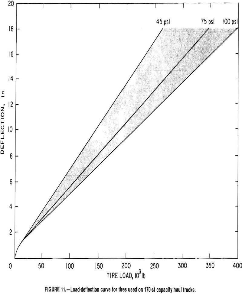
cause the bumper to strike the rear suspension of the truck, the forces on the the bumper will be higher.
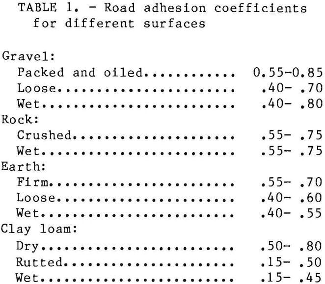
The road adhesion coefficient is a measure of the ability of the tires to grab or adhere to the road surface. As the coefficient is increased the force required to make a stationary truck slide increases. As shown in table 1, the road adhesion coefficient is dependent on the type and condition of the road surface.
Except for the Terex 33-15B, the rear tires of haulage trucks extend beyond the frame and rear suspension members. The distance from the back edge of the tire to the rear suspension struts is approximately 18 in on all of the other 170-st- capacity trucks. On the Terex truck both the suspension struts and the rear-end housing extend beyond the rear edge of the tires. In certain cases where the trucks are misaligned it is possible to deflect the tires to the rim, or approximately 30 in.
The angle of impact is an important design factor because, as the angle increases, the side loads increase and the amount of protection to the operator will decrease. This angle is a matter of circumstances under which one operator does not see the other truck and backs into it. It is felt that if the angle between the two trucks is such that if any part of the second truck, from the center of the rear tires forward, is visible in the mirror of the truck backing up, then
there should be no collision. At this angle of approximately 15° or sharper, an operator should be able to see a second truck in the rearview mirror.
Since both the force required to slide a stationary truck and the energy of a moving truck increase as the weight of the trucks increases, the worst case collision is where a loaded truck runs into another loaded truck that is parked with its brakes applied. In order to complete the dynamic analysis of the maximum forces generated during a collision between two trucks, it is assumed that the energy of the moving truck is conserved. This is the case when there is no bending or breaking of components on either truck.
Since energy is conserved, the initial energy of the moving truck is equal to the combined energy of the two trucks at any given time, plus the energy dissipated in the rear tires of the second truck, plus the energy expended in the moving of the second truck.
The following can be used to express the energies:
Energy of the first truck before impact = ½M1V²0.
Energy of the first truck after impact = ½M1V²1.
Energy of the second truck after impact = ½M2V²2.
Energy dissipated by moving second truck = FfY.
Energy dissipated into rear tires = ½KX².
These terms are combined to write the following equation:
½M1V²0 = ½M1V²1 + ½M2V²2 + FfY + ½KX²……………………………………………(1)
where M1 = effective mass of truck 1,
M2 = effective mass of truck 2,
V0 = initial velocity of truck 1, ft/s,
V1 = velocity of truck 1 at any given time after impact ft/s,
V2 = velocity of truck 2 at any given time after impact, ft/s,
Ff = weight of truck, lb, times road adhesion coefficient (frictional force, lbf)
Y = displacement of truck 2, ft,
K = deflection rate of tires, lbf/ft,
and X = distance tires deflect, ft.
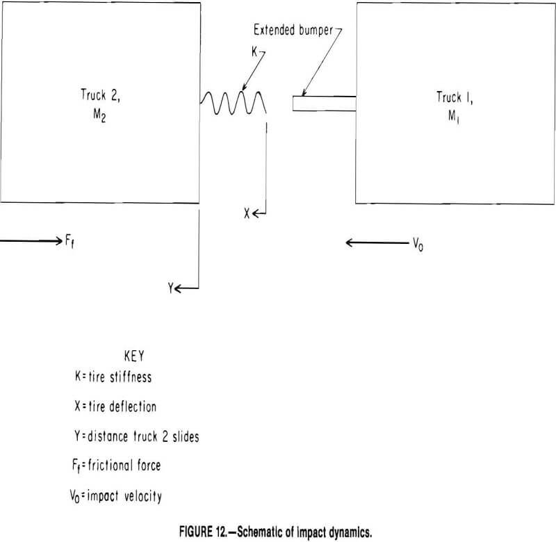
Figure 12 shows a schematic of the impact dynamics.
There are four basic steps in a typical rear-end collision for which this equation applies:
- Tire just before impact with truck 1 at a given weight and velocity.
- Time after impact with truck 2 still stationary with an increasing amount of rear tire deflection.
- Time after impact with truck 2 sliding on road with a given adhesion coefficient and an increasing amount of rear tire deflection.
- Time after impact when both trucks come to rest.
For the case that both trucks are of equal weight M1 = M2 = M and M = (weight of truck/gravity) (rotational constant), where the rotational constant is due to mass of rotating parts = 1.15.
The equation is written as follows:
When the trucks have come to rest, V1 = V2 = 0, and the equation can be written as:
![]()
Since the total energy of the system is simply the kinetic energy of truck 1 before impact, the following equation holds true:
Etot = ½MV²0……………………………………………………………………..(4)
Equation 3 may be rewritten as follows to find the displacement of truck 2 if X and E totals are known:
Y = Etot/Ff – ½ KX²/Ff………………………………………………………….(5)
Also, the following relationship between X and Y holds true:
Y = X – X0…………………………………………………………………..(6)
where X is the deflection required for truck 2 to start slide, which is 0 determined with the following equation:
X0 = Ff/K.
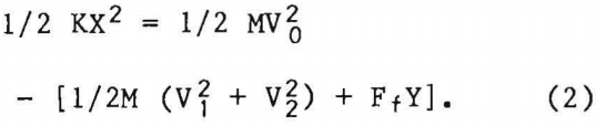
For the case of maximum tire deflection the total energy of the system can be determined for any given tire pressure using the following equation:
Etot = Ff(X – X0) + ½KX²…………………………………………………………(7)
Figure 13 shows the relationship of the energy that is absorbed by the tire deflecting and the machine sliding on the
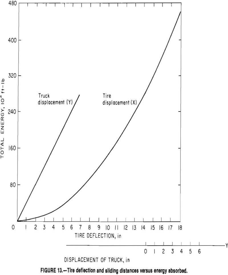
ground. The velocity of truck 1, which will deflect the tires to the maximum limit before any metal contact occurs between the two trucks, can be determined with the following equation:
V = Ff (X – X0) + ½ KX²/½ M…………………………………………………………………………(8)
Figure 14 shows the velocity of truck 1 to deflect two rear tires to the maximum limit as a function of tire air pressure for the case of the heaviest 170-st capacity truck, which has a gross vehicle weight of 575,000 lb and the highest road adhesion coefficient (from table 1) of 0.85.
Impact Forces
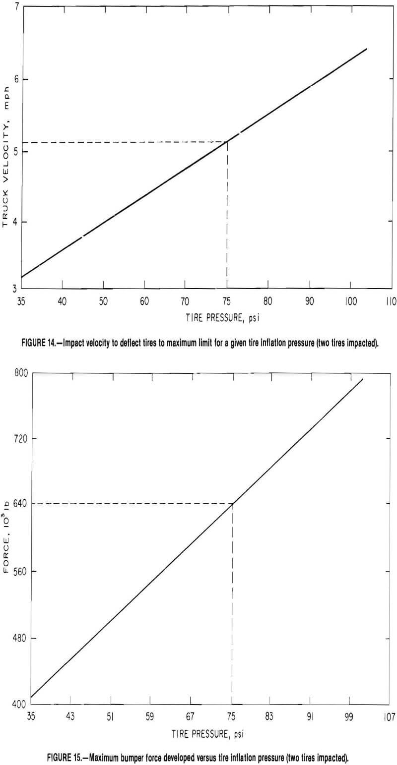
The horizontal force on the bumper at any given time is described as follows:
Fb = KX……………………………………………………………………………………(9)
where Fb = force on bumper, lb,
K = deflection rate of tires,
and x = deflection of tires.
Figure 15 shows the horizontal bumper force as a function of tire pressure for the case where the bumper impacts two tires. Figure 16 shows the horizontal force on the bumper as a function of velocity where the bumper impacts two tires with a given air pressure. For the case where the collision occurs with the two trucks at an angle to each other, a side load is introduced onto the bumper.
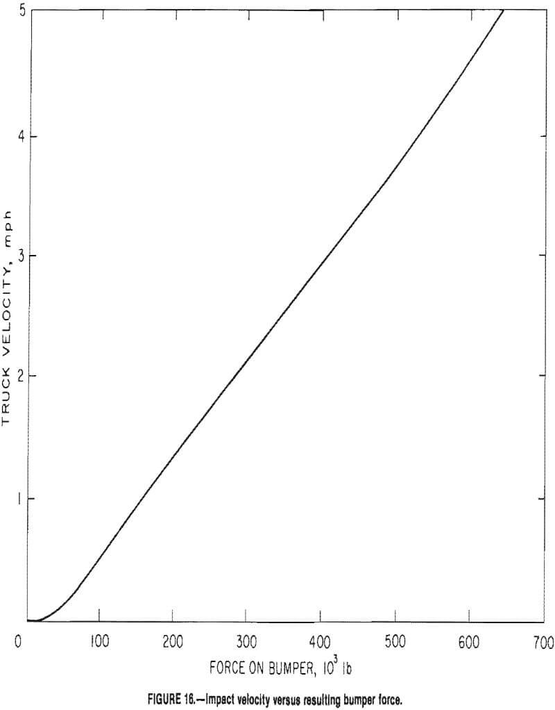
For this type of collision the forces acting on the bumper can be broken down as Fb side = Fb sin ∅ and, Fb front = Fb cosine ∅, where ∅ is the angle between the trucks, degrees, and Fb is the force due to tire deflection.
Any vertical loads on the bumper are the result of the trucks being at an angle to each other or vertical misalignment between the bumper and the rear tires. As shown in figure 14, the only bumper that would normally not make contact with the center of the rear tire is that of the Terex 33-15B, since the top of its bumper is 4 in lower than the center of the tire. This amount of misalignment will result in a vertical load of 6 pct of the frontal load. For a 640,000-lb frontal load, the vertical load due to misalignment is 38,400 lb.
Specifications
The main supports of the extended bumper must line up directly with the frame rails of the truck. It is critical that the dimensions of the frame rails on any truck are known before an extended bumper can be designed.
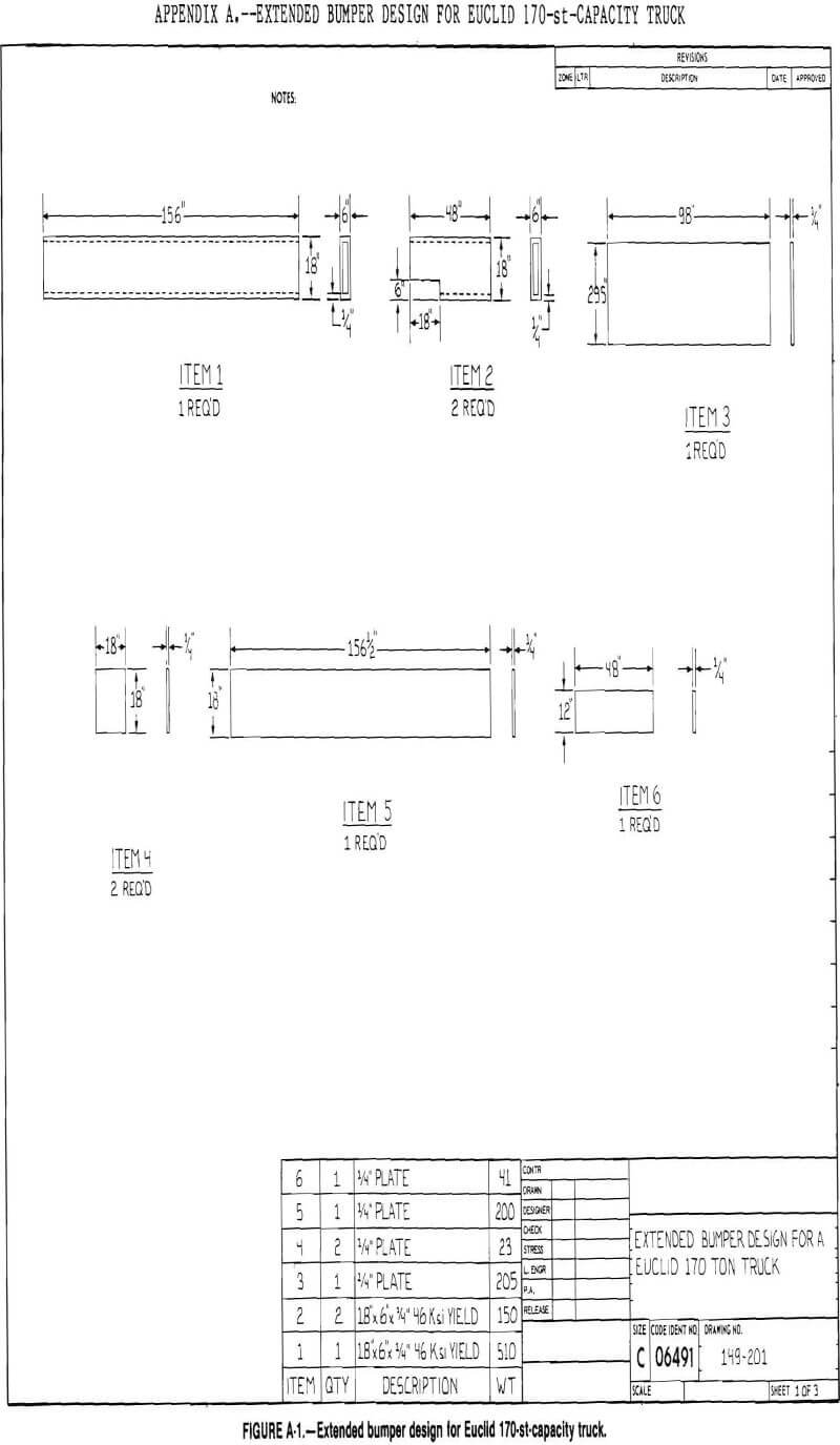
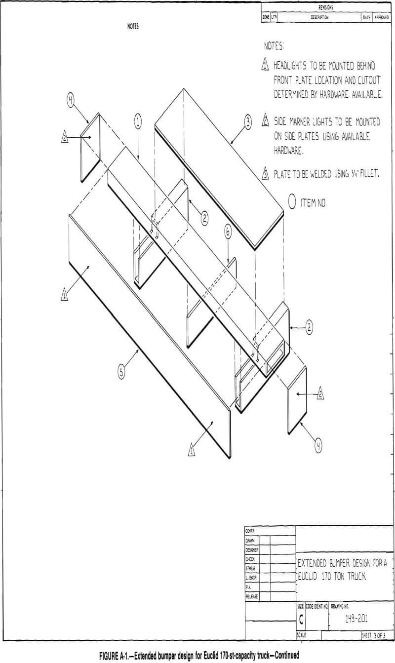
Euclid R-170
The frame rails on the Euclid consist of a 12-in-high by 10-in-wide fabricated box section. The top and bottom plates are 1 in, and the side plates 5/8 in. The frame is constructed of high-strength alloy steel with a yield stress of 100,000 psi. The distance between the Inside edges of the frame is 92 in. The front edge of each frame rail flares into the bumper and is 2 ft wide at the rear of the bumper. The bumper consists of a box section 14 in high by 8½ in wide.
In order to mount the extended bumper (appendix A) on the truck, the front and top of the existing bumper will have to be reinforced to prevent it from collapsing from the impact loads. This can be accomplished by using a plate to form a pad onto which the extended bumper main supports would be welded.
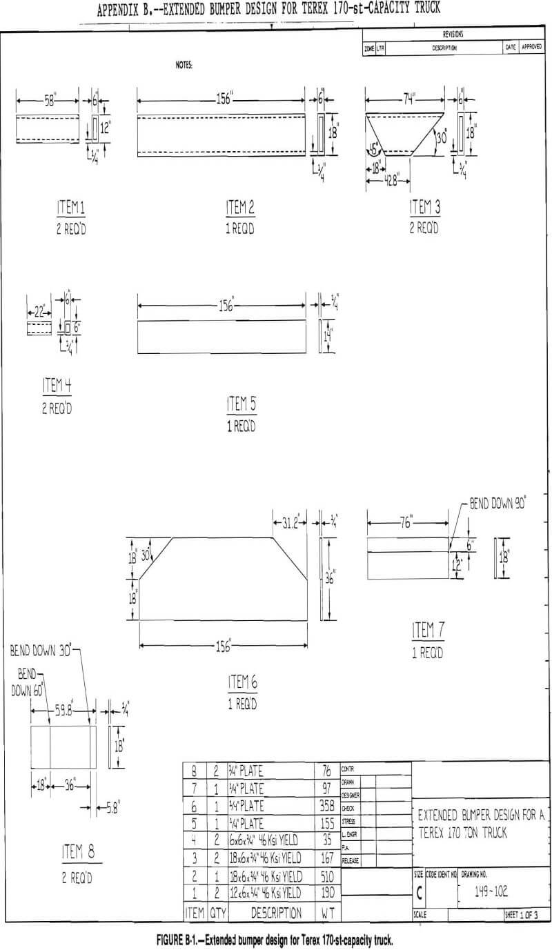
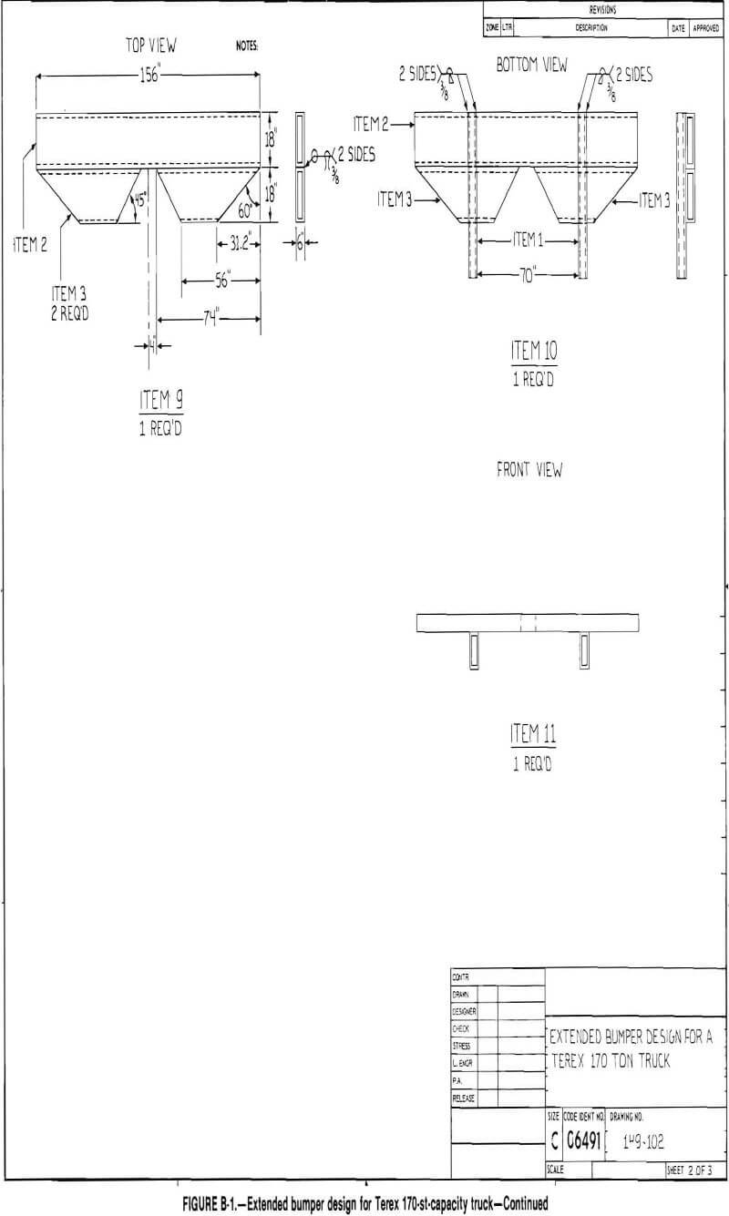
Titan 33-15B
The frame rails on the Titan consist of a 20-in-high by 8-in-wide box section. The top and bottom plates are 1 in, and the side plates are ½ in. The distance between the inside edges of the frame rails are 68 in. The frame is constructed using a medium-strength steel alloy with a yield stress of 45,000 psi. The front bumper is bolted to the frame rails, so it can be removed when the power module is removed.
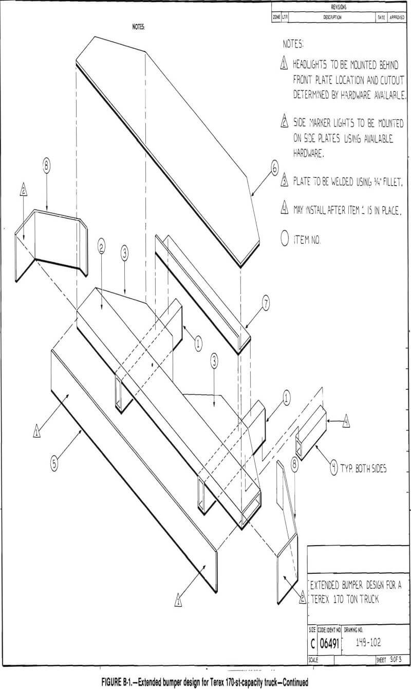
The original bumper will have to be reinforced in order to install the extended bumper (appendix B). In addition, since the bumper must be removable, any accessories mounted on the bumper must be easily disconnected from the truck.
Unit Rig Mark 36
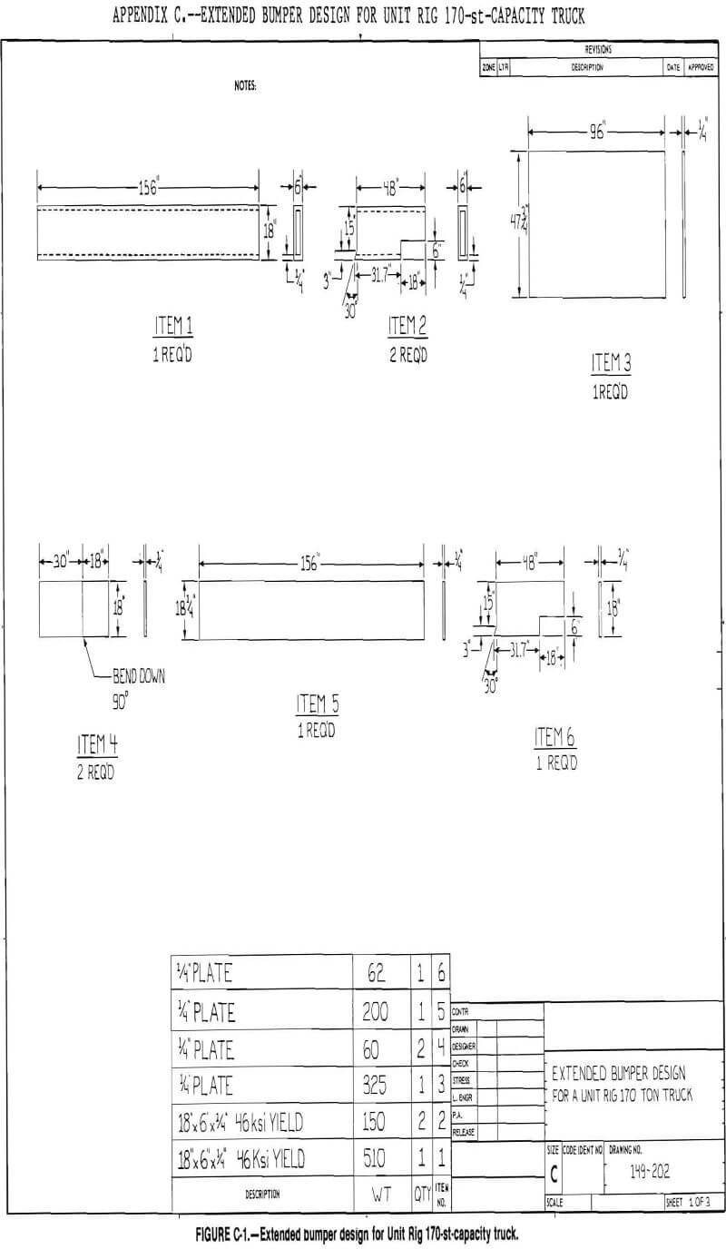
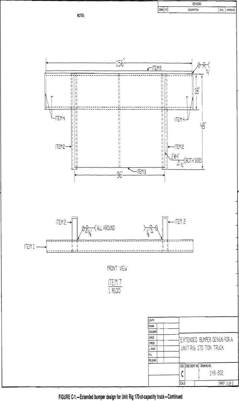
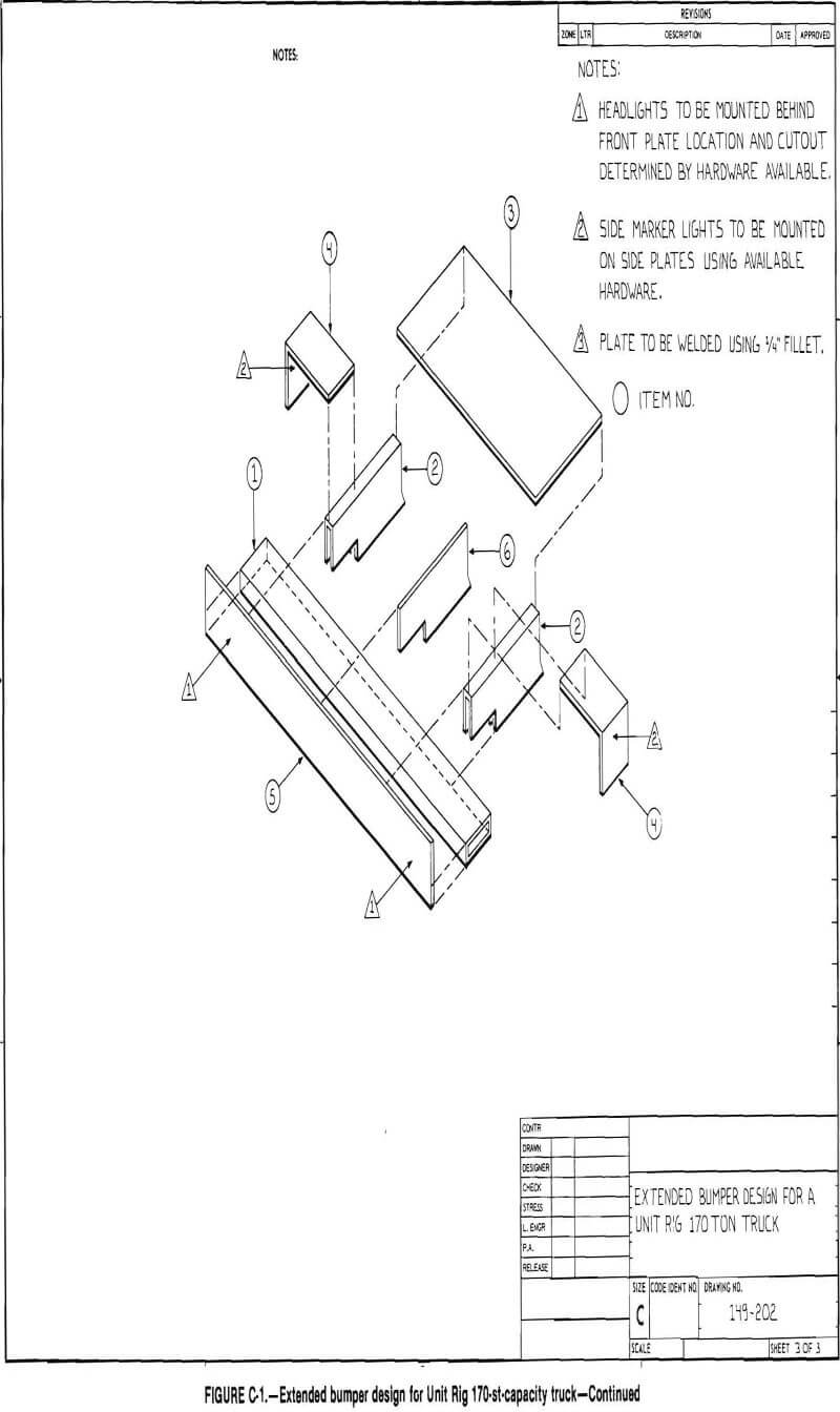
The front rails on the Mark 36 consist of a tapered box section with a distance of 90 in between the inside edges. The front of the frame is 11 In high by 3 in wide, with 5/8-in top and bottom plates and 7/16-in side plates. The frame rails are constructed from 100,000-psi yield stress steel and form the outer sides of the front bumper. The bumper is fabricated from ¼-in plate with the lower part supporting the steering pivots. Only minor reinforcement of the bumper is required to mount the extended bumper (appendix C), since the frame rails ex-tend to the front of the bumper.
Wabco 170C
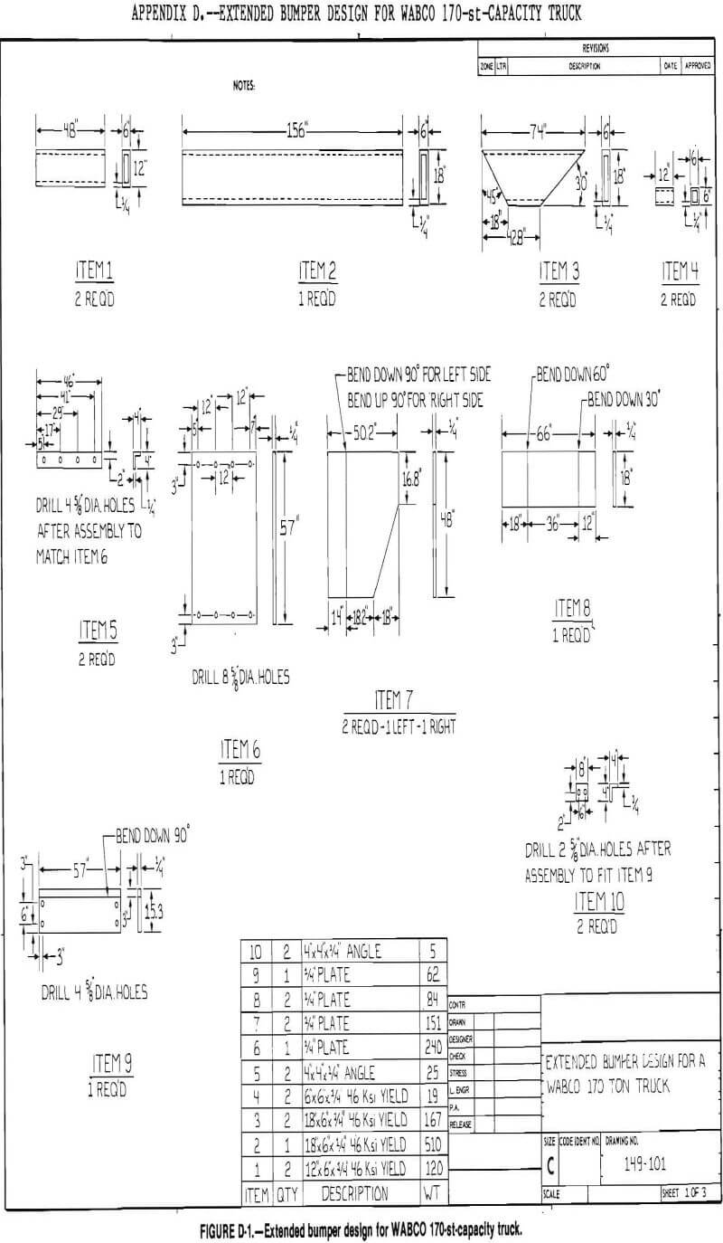
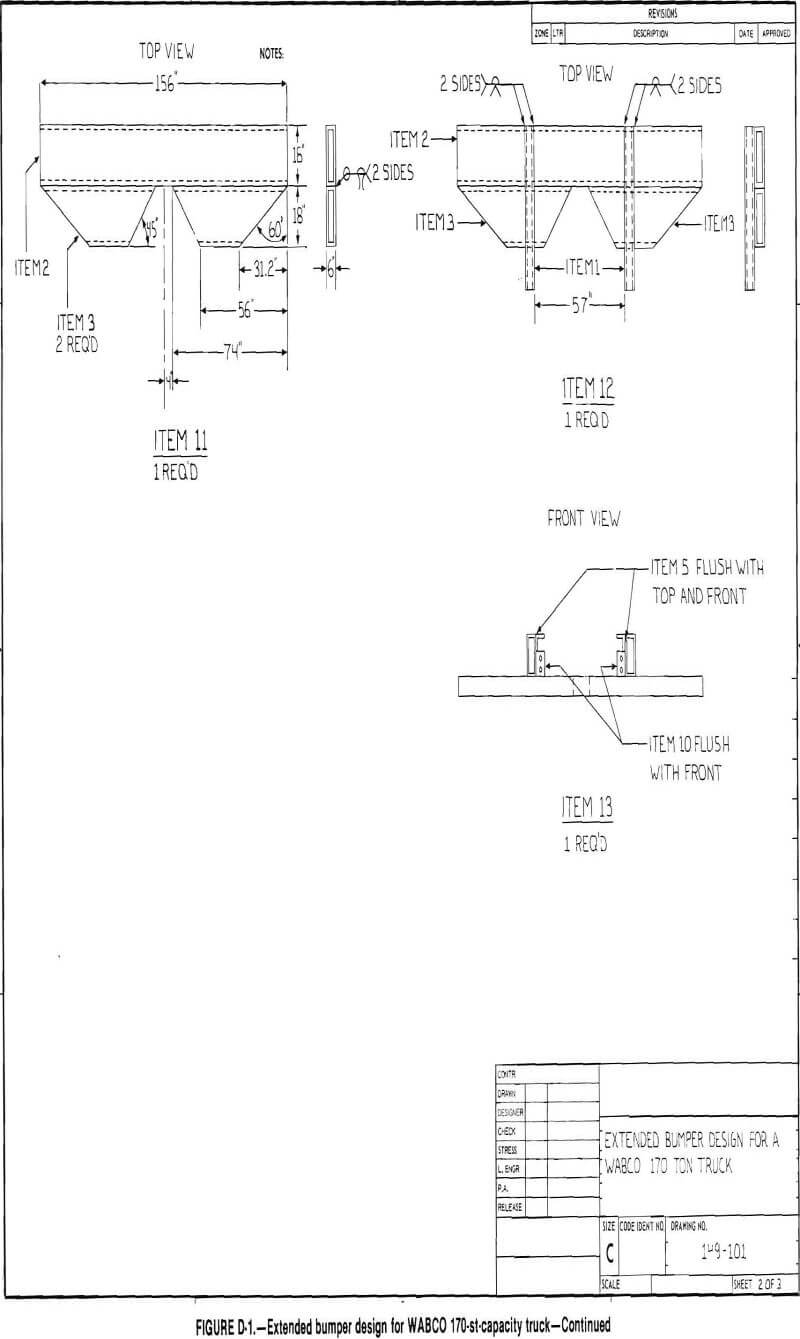
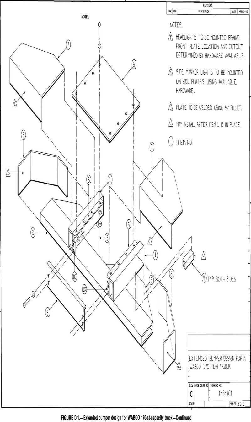
The WABCO frame consists of a box section 17 in high by 4½ in wide with 1½-in top and bottom plates and 5/8-in side plates. The distance between the frame rails is 57 in. The frame is constructed of high-strength steel alloy with a yield stress of 100,000 psi. The front bumper is ¼-in plate with a removable section in the center for removing the power module. Only minor reinforcement of the existing bumper is required in order to mount the extended bumper (appendix D), since the frame rails extend to the front of the bumper.
Summary
Bumpers based on the extended bumper designs developed will provide operator protection for rear-end collisions of 3 to 5 mph when installed on rear-end dump trucks. The use of such bumpers should reduce the extent of truck damage. Although the detailed designs included in the appendix are applicable to 170-st-capacity trucks, with minor modifications, application on other sizes and models is possible. The major differences would be the spacing of the two main structural members in order to match the various frame widths. The bumpers’ length, width, and height above ground would not vary.