Table of Contents
In the clay-HCl miniplant, leaching sized, calcined kaolin with HCl was carried out in 50-gal, glass-lined continuous, stirred tank reactors (CSTR’s). Originally four reactors arranged in a cascade configuration were used, but experience showed that acceptable alumina extraction was obtained with three reactors. The fourth reactor was kept on a standby basis. The reactors were equipped with one h-baffle and a standard three-arm, tubular retreat-curve impeller operated at 120 r/min. This arrangement did not prevent centrifugal classification of the reactor contents. Several 5- and 10-day miniplant leaching campaigns, made with a solid-liquid separation section that evolved to five thickeners and four classifiers, indicated that excessive fines were a problem. The problem became acute during an operation using minus 8-mesh calcined kaolin. The quantity of fines generated during leaching resulted in a viscous pulp that increased the suspension of the larger particles and prevented their effective separation in the spiral classifiers. Returning to minus 10-mesh feed eliminated the thick viscous pulp that could not be separated in the spiral classifiers.
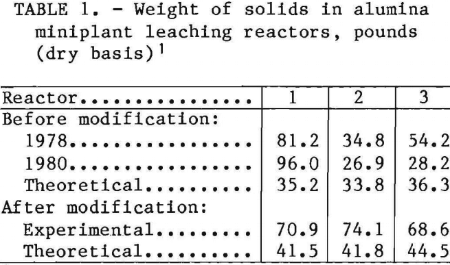
At the end of several leaching operations, the total weight of the leaching slurry, the solids in each reactor, and the particle size distribution of the solids were determined. The data showed that the first reactor contained an excessive amount of solids, 81.2 to 96 lb, compared with 35.2 lb theoretical, while the second and third reactors had lesser amounts (table 1). This finding suggested that the retreat-curve impellers, operating at 120 r/min and with inadequate baffling, did not produce adequate slurry suspension and permitted centrifugal classification of the reactor contents. The swirling mass of particles in the lower portions of the reactors became large enough so that fines were generated by autogenous grinding.
An investigation was made to determine the contribution of chemical and mechanical attrition to the degradation of calcined particles during leaching, and the CSTR’s were modified to decrease the accumulation of coarse feed particles in the lower portions of the reactors. Another approach to the problem was to use minus 18-mesh calcined kaolin feed produced by a “misting” method.
Miniplant Description
The leaching section of the miniplant consisted of three 50-gal, glass-lined Pfaudler reactors in cascade (fig. 1). Each reactor was 24-in ID by 26-5/8 in
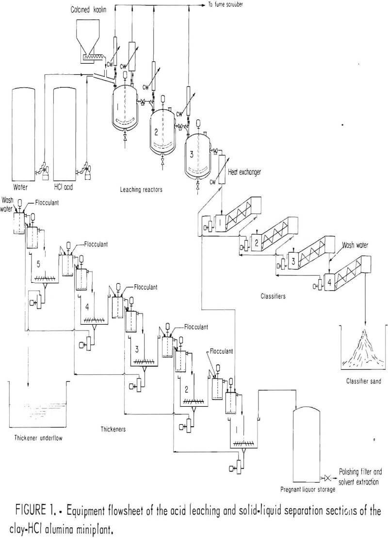
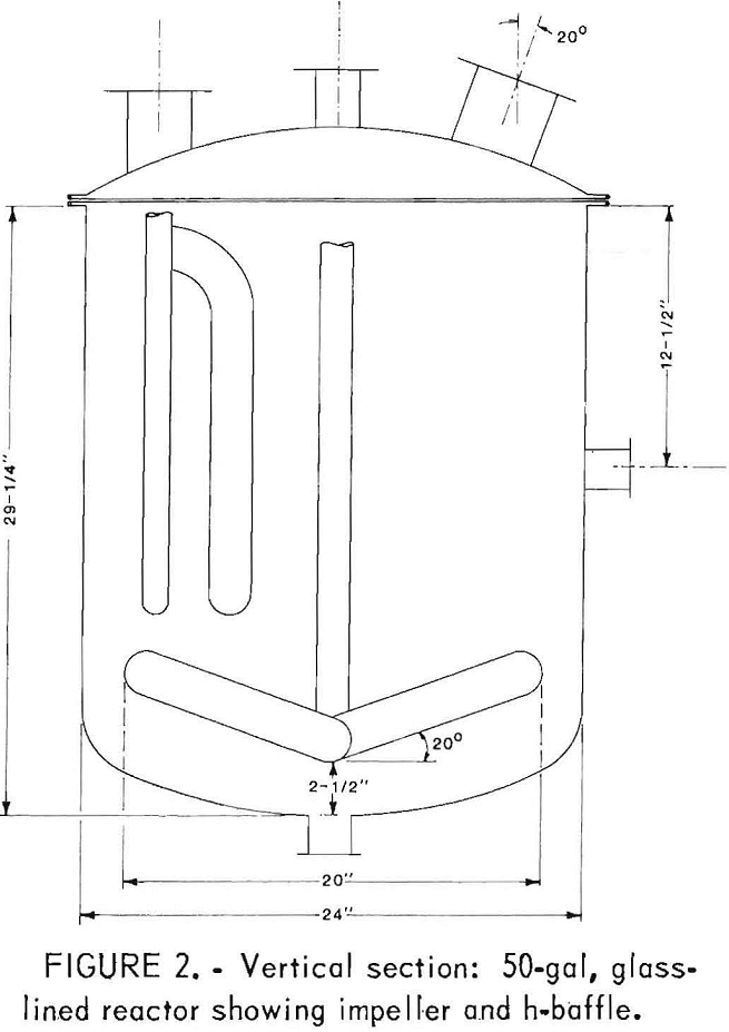
tall, and the contents were mixed by a glass-coated retreat-curve impeller with three arms. The diameter of the circle swept by the arms was 20 in. Limited baffling was provided by one h-baffle, which also served as a thermowell. The cross section of an original reactor is shown in figure 2.
Before reactor modification, the hot slurry overflowed from the side discharge of one reactor to the top inlet of the next. Slurry from the last reactor discharged through a heat exchanger to the solid-liquid separation section. Three-way valves between reactors permitted sampling of the slurry stream during operation and isolation of each reactor during shutdown. The flowsheet of the leaching and solid-liquid separation sections of the clay-HCl miniplant is shown in figure 1.
Experimental Procedures
Bench-Scale Leaching
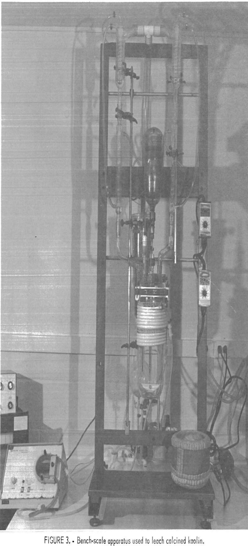
Calcined kaolin was leached in a 4-L resin kettle with a 25-pct HCl solution. Conditions of minimum mechanical attrition were produced by stirring the contents with a Teflon tetrafluoroethylene polymer (TFE), half-moon-shaped blade at 185 r/min in the apparatus shown in figure 3. In these tests, the acid in the resin kettle was heated to boiling, and then the calcined kaolin was added. The initial exothermic reaction was controlled by temporarily replacing the heating mantle with a water bath. After leaching at boiling for 1 h, the contents of the flask were cooled, and the residue
was filtered and wet screened. The sized fractions were dried at 125° C for 24 h and weighed.
For reaction rate studies, the same apparatus was used. To establish a time for the start of the reaction, the HCl was heated to boiling, and the calcined kaolin was added. The time of addition was noted, and samples of the reacting slurry were withdrawn at 2, 4, 8, 16, 32, and 60 min. The samples were immediately quenched in an ice-water mixture to retard the reaction by dilution and to decrease the temperature to almost 0° C. The liquids were analyzed for alumina.
Bench-Scale Attrition Testing
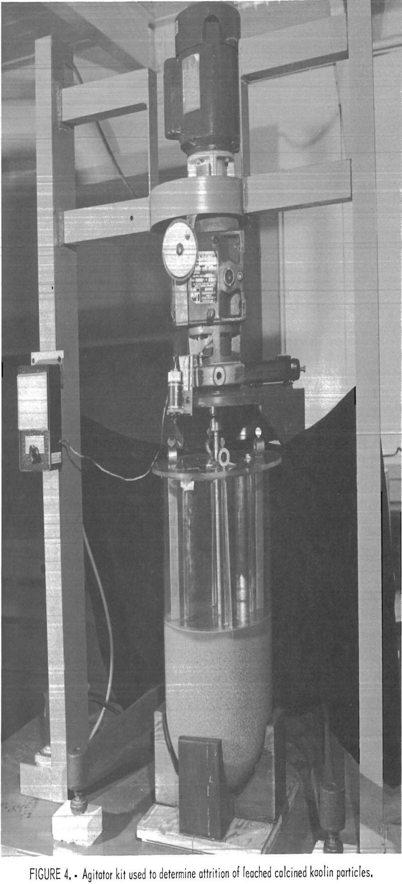
Bench-scale attrition tests were conducted with a Chemineer BENCO model ELB test kit, shown in figure 4. Agitator speed was varied, and two types of impellers were used. Horsepower values were relative because of the low torque readings obtained under experimental conditions, which reflected low viscosities of the slurries.
Miniplant Procedures
Miniplant operations were begun by filling the first reactor with 26-pct HCl and heating the acid to boiling. Then both HCl and calcined kaolin feeds were begun. This procedure avoided the uncontrolled exothermic reaction that occurred if a large amount of cold kaolin and acid were heated to the boiling point. Concentrated HCl and water were delivered by metering pumps, and the calcined kaolin was delivered by a weigh-feeder. All feed rates were controlled to within 1 pct. Samples were taken on a predetermined schedule for both the leaching section and the solid-liquid separation section. The streams between the reactors
and at the discharge of reactor 3 also were sampled.
At the end of the run, the reactor contents were dumped into cold water to quench the reaction. A measured volume of water was used to flush the reactor bottom valve clear, the valve was opened, and the slurry flowed into a tared tank of cold water. Weighing the tank provided the weight of the slurry. Weighing and sampling the wet residue gave samples for moisture determination, wet screen analyses, and chemical analyses. The dynamic or stirred water volumes were measured by filling the reactor with water until it overflowed, with the stirrer running, then dumping the reactor contents and measuring the liquid volume. Chemical analyses were conducted on liquid and solid portions of the reactor streams. A material balance was calculated for the miniplant leaching circuit operation.
In order to characterize the 50-gal CSTR’s in the clay-HCl miniplant, the amount of short-circuiting or bypassing and the amount of dead space in each reactor were determined at a feed rate of 100 lb/h of minus 10-mesh calcined kaolin. Copper was used as a tracer because this element was not present in significant amounts in the kaolin. CuCl2 was fed to the first reactor at a constant rate. Samples were withdrawn at intervals from each reactor and from the discharge stream of each reactor. The samples were analyzed for copper, and the changing copper concentrations were used to calculate the effective volume, the dead space, and the short-circuiting associated with each reactor. Residual solids in the reactors were measured as described above.
Materials
Georgia kaolin was crushed and calcined to make the bench-scale and miniplant leaching feeds. Raw kaolin was crushed to minus ½ in and calcined at 750° C in a 2½-ft-diam by 20-ft-long gas-fired rotary kiln. The calcined kaolin was crushed to minus 8 or 10 mesh (market grade screens) for miniplant work, or to sizes using Tyler standard screens for bench-scale testing.
For misted feed, kaolin was crushed to minus 16 or 18 mesh and was tumbled on a 3-ft-diam pelletizing disk fitted with a nozzle that sprayed the tumbling material with a fine water mist. Enough water was used to cause the fine particles to adhere and be smeared onto the larger particles without causing agglomeration of the larger particles into pellets. The 18-mesh misted kaolin was calcined in the rotary kiln described above, whereas the 16-mesh misted kaolin was calcined in a direct, coal-fired fluidized-bed calciner.
Leached solids were prepared for attrition and agitator testing by wet screening. Wet screening created fewer fines than dry screening and provided a consistent sizing technique because the leached solids were wet screened without drying.
Discussion of Results
Bench-Scale Tests
The reaction rate and the generation of fines during stirring and by additional stirring after the chemical reaction were studied. Leaching tests were run using boiling 25-pct HCl solution in the resin kettle reactor (fig. 3) and crushed calcined minus 10- plus 14-mesh and minus 65- plus 100-mesh kaolin. The reaction rate studies were based on timed and quenched liquid samples for alumina analyses. Results are shown in figure 5, in which the percentage of acid-soluble alumina extracted is plotted against elapsed leaching time. The straight line relationship during the initial stage of leaching typifies the zero-order kinetics of a diffusion-controlled reaction (9-10). The minus 65- plus 100-mesh particles leached faster than the minus 10-plus 14-mesh particles. Eighty percent
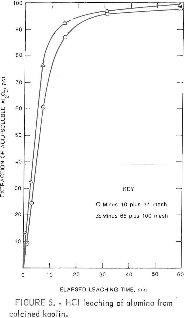
of the alumina was extracted in 8 min. After this level of extraction, the reaction rate decreased and deviated from zero-order behavior. Leaching kinetics for a similar calcined kaolin were investigated by Olsen.
Degradation of calcined kaolin particles is caused by physical attrition and acceleration of the physical attritioning process by chemical leaching and weakening of the particulate structure. An investigation was carried out to determine the structural weakening of the calcined kaolin particles by acid leaching. Minus 10-mesh calcined kaolin was leached for ½, 1, and 2 h (fig. 6). Wet screen analyses of the residue are compared with the initial analysis of minus 10-mesh
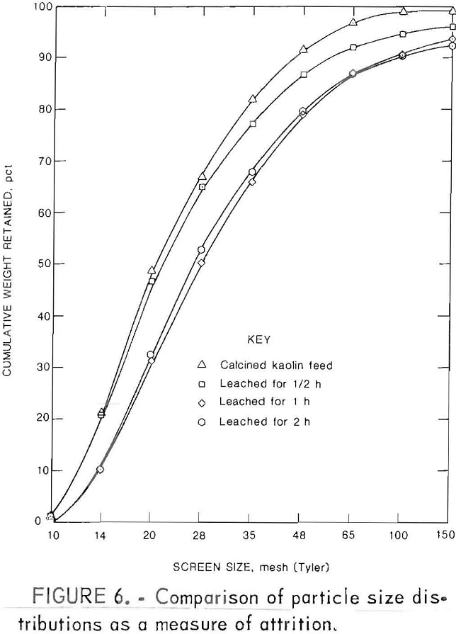
feed. Fines were generated during the first and second half hour periods. A small change occurred during the second hour of leaching.
Batch leaching differs from miniplant leaching in that the chemical concentrations change, during the test. The particles become more porous and their bulk density decreases, and the liquid becomes denser as Al2O3 dissolves and forms AlCl3. The leached solids become more buoyant and easily suspended toward the end of batch leaching. To determine the effect of agitation in the higher density miniplant leaching liquor, samples of calcined kaolin were agitated for 1 h in a boiling AlCl3 solution having a 1.28 density at 25° C. The tests were performed in the apparatus shown in figure 3. Results of wet screening of the solids are compared in figure 7, which shows that the attrition of calcined kaolin was only slightly greater during acid leaching than during boiling with AlCl3 solution. Leaching was a small factor in the
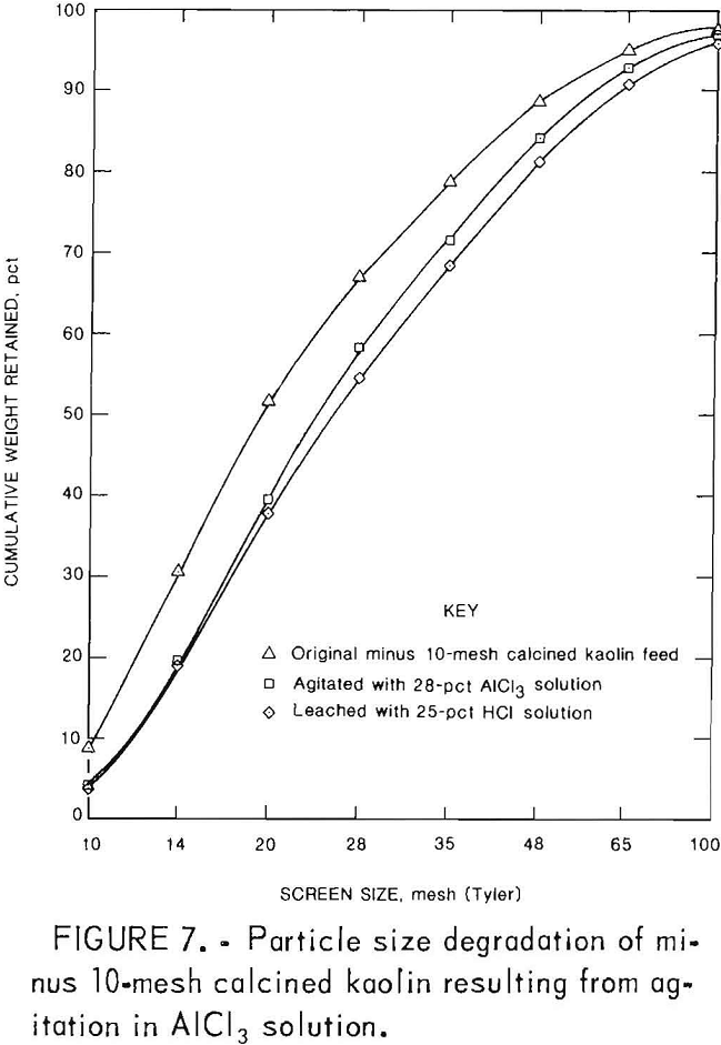
generation of fines, and feed degradation in the clay-HCl miniplant was caused primarily by mechanical attrition.
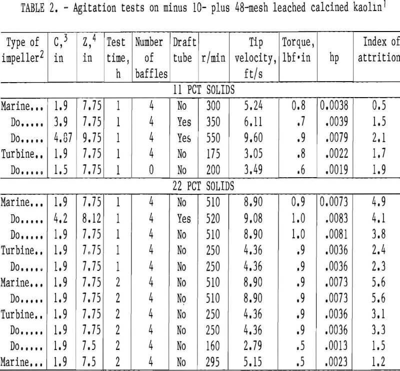
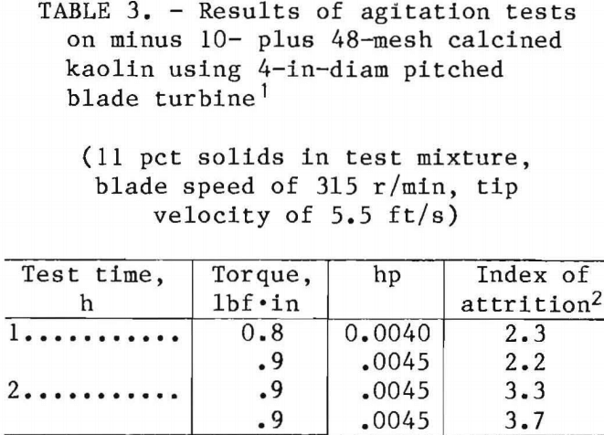
Agitation tests were carried out on leached calcined kaolin particles in the test kit shown In figure 4. Tests were made to determine the amount of attrition caused by the rotating impeller and the confining surfaces of the vessel. The speed of agitation was varied between 160 and 550 r/min. Two types of impellers, a three-bladed marine propeller and a 45° four-bladed pitched turbine, both 4-in diam, were used in the baffled glass vessel. The amount of material passing a 48-mesh screen was used as the quantitative measure of attrition. Horsepower values were relative rather than absolute because of the low viscosities of the slurries. Initial tests using 11 pct solids in a 28-pct AlCl3 solution were performed to correspond to conditions experienced in the alumina miniplant.
Results of the tests are listed in table 2 and show that using sufficient agitation to suspend the solids to 98 pct of the fluid height in the vessel caused minimal attrition, which was usually less than 2 pct. The percentage of solids was doubled to 22 pct, but attrition was less than 5 pct. The agitation time was increased from 1 to 2 h, but no severe attrition was observed. In an attempt to promote attrition, tests using 11 pct solids were rerun with unleached minus 10- plus 48-mesh calcined kaolin in water. The kaolin was crushed and screened and had sharp edges and corners, which should enhance particle degradation if contact between particles and with the impeller or vessel were the cause of particle degradation. Data in table 3 show that attrition was less than 4 pct for all samples.
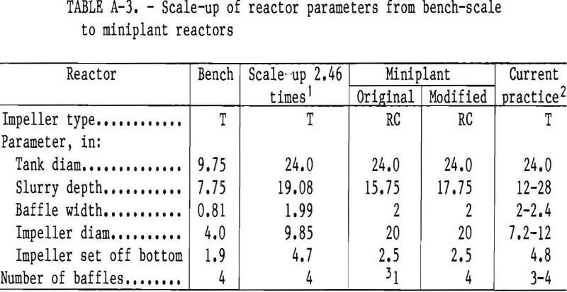
The conclusions drawn from the bench-scale testing were that (1) the chemical leaching process contributed only a small fraction of the fines, (2) the mechanical agitator and baffles in the test cell added less than 4 pct to the accumulation of fines in a properly suspended slurry, and (3) the excessive amounts of fines produced in the miniplant reactors must be generated by mechanical stirring and the contacting of large particles, which are partially suspended in the lower portions of the reactors. A listing of scale-up parameters, from bench-scale to miniplant reactor size, is given in table A-3, in the appendix.
Modification of Miniplant Reactors
Most miniplant runs were made with a minus 10-mesh calcined kaolin feed in which fines were part of the feed. When the feed was changed to minus 8 mesh, the generation of an excessive amount of fines resulted in the formation of a stable froth that filled the three leaching reactors and disrupted the operation of the solid-liquid separation circuit. Returning to a 10-mesh feed restored the miniplant to stable operation but left the problem of obtaining further improvements in the leaching operation.
Note.—Solids suspension level was 98 pct of height.
Note.—Solids suspension level was 98 pct of batch height.
The residues in the reactors after miniplant leaching operations contained large particles, which accumulated in the lower part of the reactors, contributed to a nonproductive dead space, and slowly ground themselves into fine particles. Eliminating the accumulation of particles in the reactors became the prime objective of this investigation.
Bench-scale batch-leaching tests demonstrated that some fines were generated during the first part of the leaching period and were presumably from corners, edges, and other fragile surfaces of the calcined kaolin. Agitation of suspended particles with pitched turbines or marine propellers produced only very small amounts of fines. In order to prevent or limit the formation of fines, the miniplant reactors required modification to suspend 10-mesh feed and to uniformly discharge all particle sizes. Finer feeds and innovative feed preparation methods such as “misting” were also considered.
In scaling up from bench to miniplant scale, the principal guide is dimensional similitude. Ratios of impeller size, baffle width, and slurry depth should be similar, within the constraints of the existing miniplant with one to four reactors.
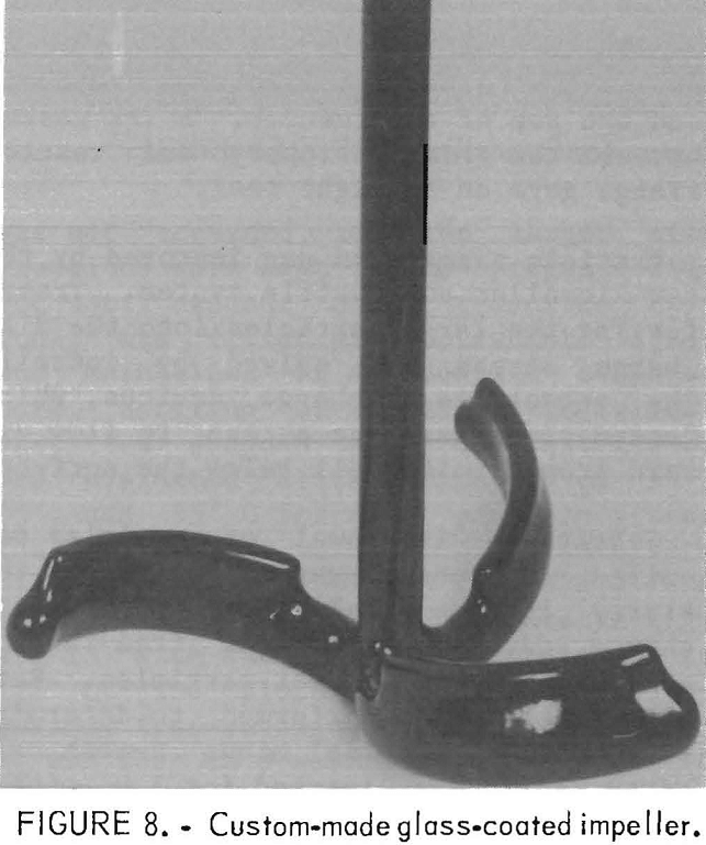
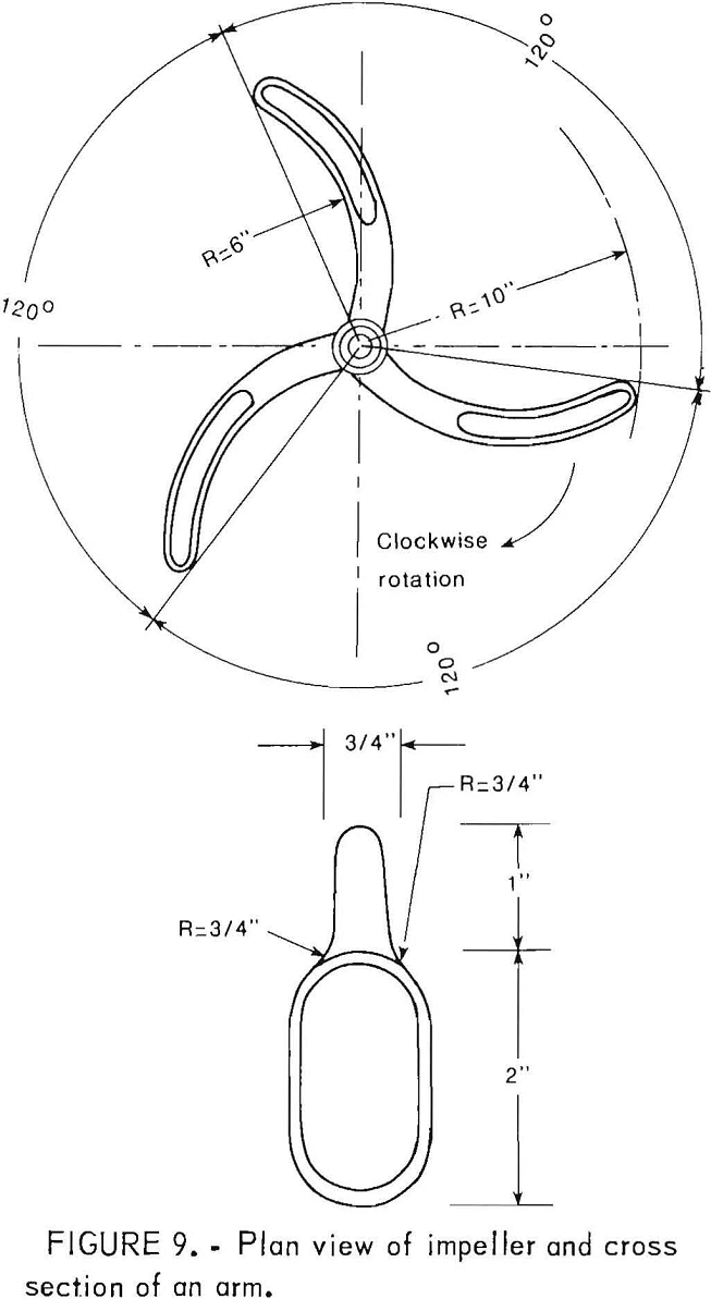
The existing reactors were conventional, “jacketed glass-lined steel tanks with three-blade, retreat-curve impellers that swept an area of 20-in diam and were spaced 2½ in from the bottom. Pitched turbine impellers for the 24-in-diam tank should be 7- to 11-in diam and positioned 4 in from the bottom, but suitable glass-coated turbine impellers were not commercially available. Therefore, the 20-in retreat-curve impeller design was modified by welding a 1-in-high by 6-in-long rib to the upper surface of each blade before glass-coating. The new glass-coated impellers (figs. 8-9) were manufactured by the Pfaudler Co., which has
subsequently introduced a glass-coated 45° pitched turbine impeller.
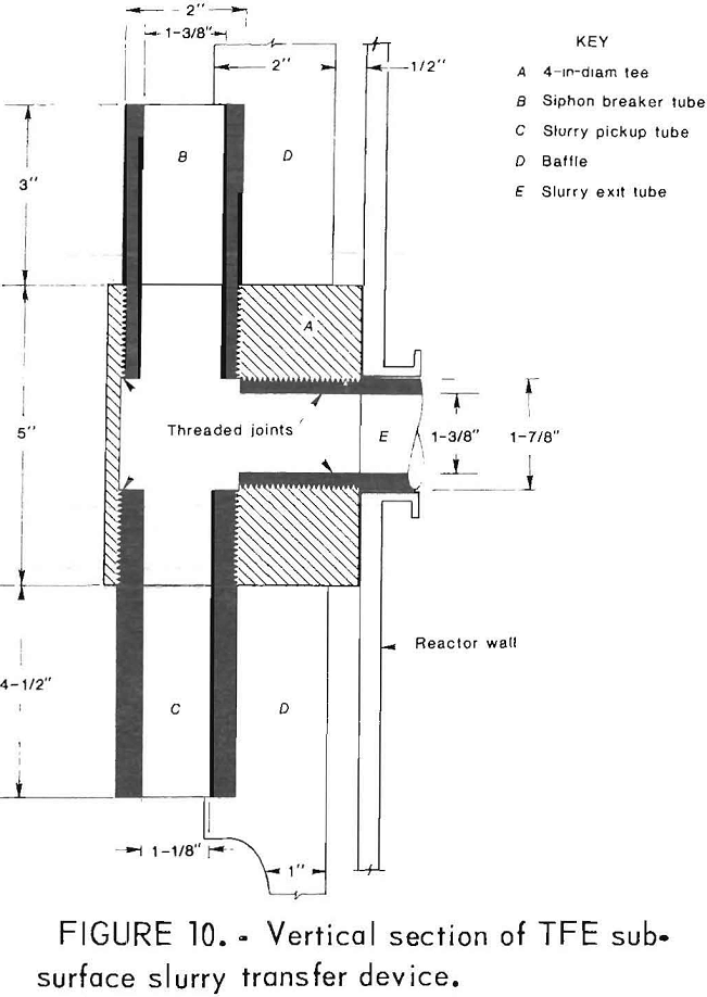
Reactor changes were aimed at preventing the accumulation of coarser particles in the lower regions of the reactors by increasing particle suspension. A vertical section of the baffle assembly and subsurface slurry discharge device is shown in figure 10. Figure 11 is a cross section of a modified reactor, which shows the modified impeller, baffles, and subsurface slurry discharge device.
TFE was selected for retrofitting the reactors because it could be easily machined and could withstand the boiling
HCl-AlCl3 and boiling HNO3-Al(NO3)3 solutions produced in the alumina miniplant. Four 2- by ½- by 24-in baffles were vertically mounted at 90° from each other in the reactor, and ½ in from the reactor wall (fig. 11). Baffle width was fixed at 2 in by the scale-up factor (4). The relationships between bench-scale, miniplant, and current practice reactor dimensions are given in appendix table A-3.
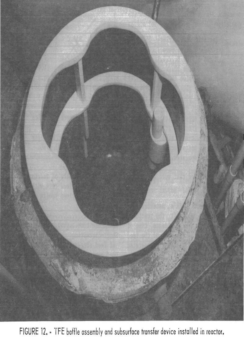
Construction of the baffle assembly was difficult because TFE creeps under stress and expands nonlinearly in the range from 0° to 112° C. Four baffles were mounted in slots through two horizontal rings. Threaded TFE rod was used to pin each vertical and horizontal intersection. The entire baffle assembly was made into one rigid structure that fitted snugly inside the reactor (fig. 12). The baffle assembly was held in position by
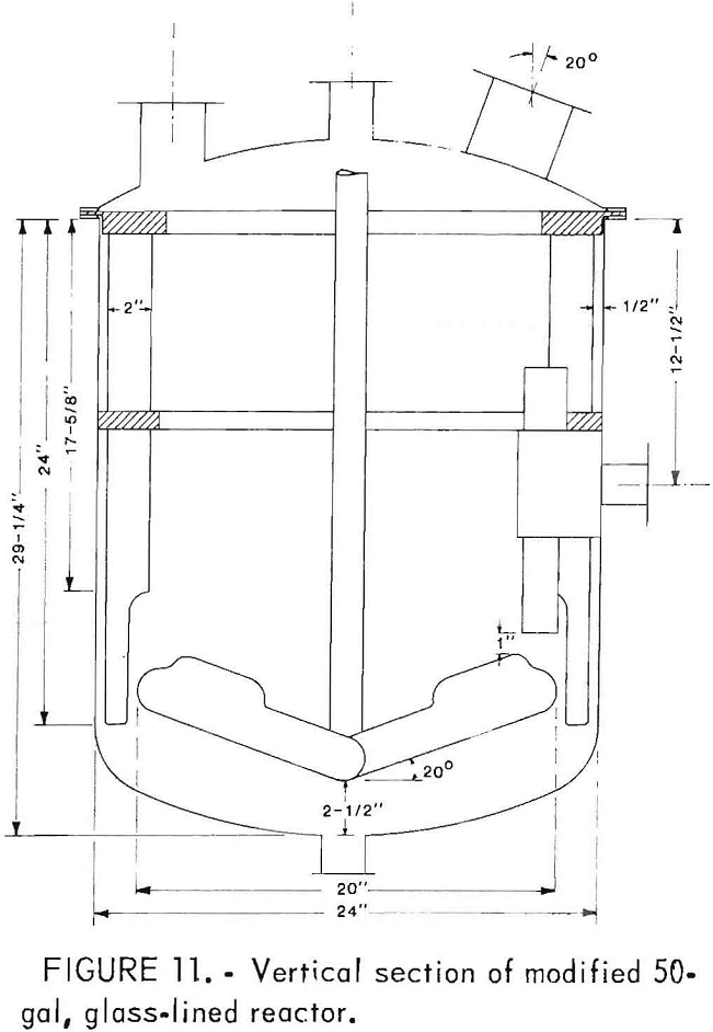
machining a 3/8-in lip in the upper ring and clamping the ring between the body and the top of the reactor. A TFE gasket between the ring periphery and reactor flange gave an airtight seal.
Particle suspension was improved by the new impeller and baffle system. Transferring the large particles into the discharge stream was solved by installing subsurface discharge devices, which forced the discharge stream to flow upward from a point well below the surface.
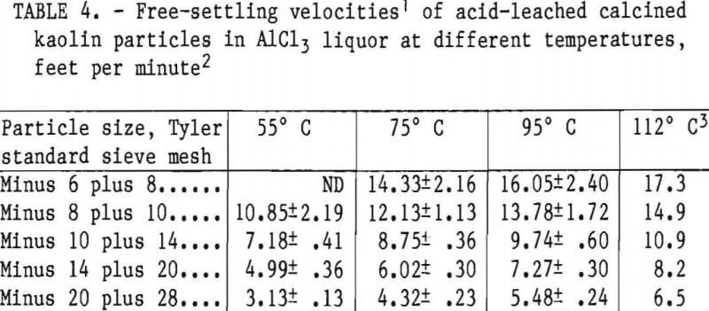
Subsurface withdrawal of particles required that the upward velocity of the slurry in the intake tube of the discharge device exceed the free-falling velocity of the largest particles. Settling tests were performed to determine these values. Nominal minus 6-mesh calcined kaolin was leached for 1 h with a boiling 25-pct HCl solution. The slurry
was wet screened, and the larger size fractions were kept in the pregnant liquor until needed. A 2-L graduated cylinder was filled with pregnant liquor and maintained at a constant temperature. Settling of solids as individual particles dropped into the test liquor was evaluated at temperatures of 55°, 75°, and 95° C for five particle sizes. The free-falling velocities of each particle size are reported in table 4 and are plotted against temperature in figure 13 with the plots extrapolated to 112° C. The plots indicated that the maximum free-settling velocity was 17.3 ft/min for an 8-mesh particle in 112° C solution.
Effects of Reactor Modification on Miniplant Leaching
Evaluation of the modified miniplant leaching section CSTR’s was combined with a program for testing a 10- by 1.5-ft continuous horizontal belt filter and different leaching feed materials. The filter tests were made with the original reactors used for earlier runs (fig. 2). Many of the data were generated during filter tests before reactor modification (tables A-1 and A-2). After the modification, miniplant leaching was continued to test the effect of the reactor changes and to evaluate the performance of the belt filter with new types of
calcined kaolin feed that were not previously available.
In the miniplant GSTR’s, material continually entered and left the reactors. In an ideal CSTR, the residence time of the solid feed is a function of the feed rate. An improperly designed or operated reactor circuit may suffer from short- circuiting or bypassing, or from the accumulation of solids in the dead space of the reactor, which decreases its effective volume. Improper operation may involve inappropriate feed size, feed rate, agitator speed, or temperature. Both short-circuiting and dead space decrease the residence time of the entering feed and lower productivity because additional reactors or larger reactors are required for the same throughput.
Characteristics of the three reactors in series were evaluated at a 100-lb/h feed rate before the reactors were modified (tables A-1 to A-3). Using a copper-tracing technique, the residence time, short-circuiting, and dead space were determined and are reported in table 5. From these results, the following conclusions were drawn:
- Individual residence times for the three 50-gal CSTR’s were from 28 to 38 min.
- Short-circuiting was minimal.
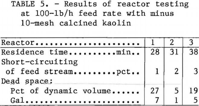
- The calculated dead space volume for each reactor was in agreement with the volume of solids in the reactors at the termination of operation and was greatest in the first reactor.
- Reactor mixing resembled that of a perfectly mixed CSTR except for the solids that accumulated in a dead space in the lower portions of the reactors.
This preliminary investigation indicated that more than one-fourth of the volume of the first reactor, and one-fifth of the volume of the third reactor, was occupied by suspended particles that acted as dead space and decreased the effective volume of the reactors. Attrition of the accumulated solids was the source of the excessive fines, because the problem increased on changing from minus 10-mesh to minus 8-mesh feed and decreased on returning to minus 10-mesh feed.
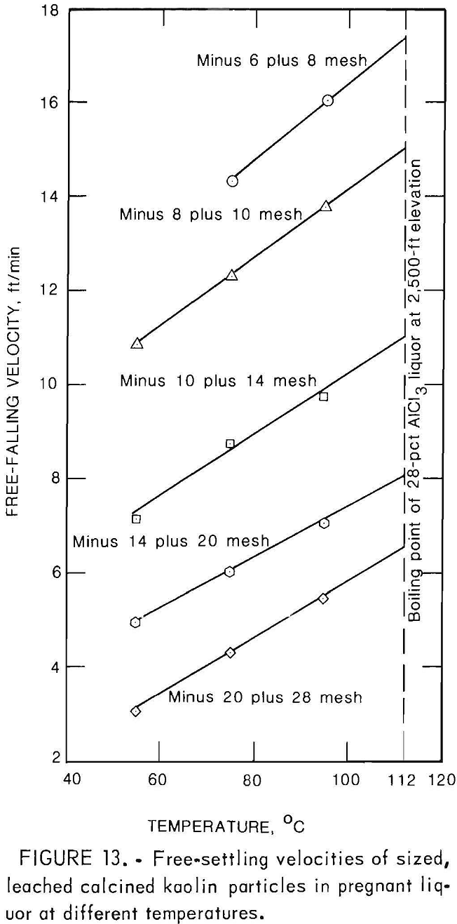
The subsurface slurry discharge system installed in the reactors was designed for a rising velocity greater than 17.3 ft/min. Two factors, the feed rate into the system and the ID of the transfer pipe, determined the rising velocity. Calculations indicated that with 8-mesh feed and feed rates of 150 lb/h or great-er, an intake pipe of 1.125-in ID was required. The subsurface discharge devices were made with 1-1/8-in-ID intake pipes (fig. 10). The changes made in the 50- gal, glass-lined CSTR’s were—
- A 1-in rib was added to the top of each impeller arm to increase the vertical surface area and to permit slower rotation for the same degree of agitation.
- Low-speed drive gears were installed to provide impeller speeds in the range of 30 to 50 r/min instead of the original 60 to 300 r/min.
- A baffle assembly with four vertical baffles, each 2 in wide, was installed to increase vertical agitation and prevent centrifugal classification of the slurry particles.
- A subsurface slurry discharge device was added to withdraw slurry from just above the rotating impeller blades and to decrease the accumulation of large particles in the lower regions of the reactors.
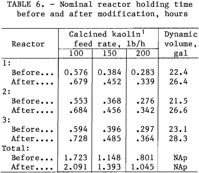
The dynamic volume was measured on the three reactors before and after the modifications, and found to increase on the average from 22.3 to 27.1 gal by the installation of the subsurface discharge devices. Table 6 lists the dynamic volumes for the reactors and the calculated residence times for feed rates of 100, 150, and 200 lb/h.
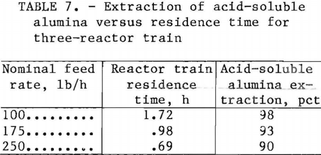
The percentage of acid-soluble alumina extracted at feed rates of 100, 175, and 250 lb/h in the unmodified reactors is given in table 7. The data show that at a 100-lb/h feed rate a total residence time of 1.72. h was observed, and that 98 pct of the acid-soluble alumina was extracted. When the feed rate was increased, the residence time of material passing through the reactors decreased, and less of the acid-soluble alumina was extracted.
Particle degradation is shown by the displacement of the particle distribution to the smaller sizes. Particle degradation produced by the original and the modified reactors can be compared by evaluating the weights and particle size distributions of the solids in the reactors during steady-state operation. The steady-state particle populations of the reactors were determined from the reactor contents at the end of a run.
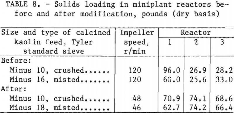
The weight of solids in the reactors should decrease when alumina is extracted, and reactor 1 should contain more residue weight than reactors 2 and 3. Changes in the solids loading in the reactors before and after the modifications are given in table 8. In the unmodified reactor train of the solids that accumulated in the three reactors, the first reactor retained 64 pct when using crushed feed and 51 pct when using minus 16-mesh misted feed, thus showing some advantage in using misted feed.
Modifying the reactors created an almost equal distribution of the residue solids among the reactors (table 8). Reactor modification caused the weight of solids remaining in reactor 1 to decrease from 96.0 to 70.9 lb, even though the reactor volume increased by 18 pct. The more uniform residue weight between the reactors indicated a more equal operation although the actual weights were about twice the theoretical value of about 35 lb for completely leached calcined kaolin (table 1).
Particle degradation in a reactor can be illustrated by plotting the cumulative screen analyses of the feed and discharge stream solids. The area between the two curves is an empirical measure of the general change in particle size. This area can be reduced to a single number, the degradation index (DI). The DI is defined as the difference between the area under the cumulative screen analysis curve for the discharge stream solids and the area under the curve for the feed and is expressed as the percentage of the area under the feed curve. The areas are approximated by the sum of the cumulative screen values, as shown in figure 14.
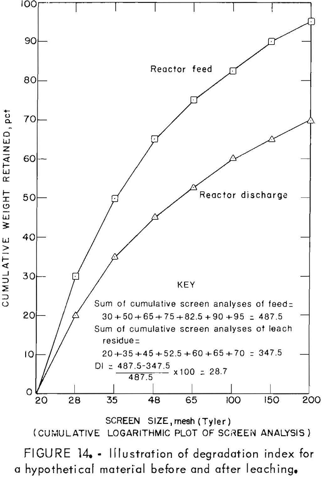
Large DI values indicate large decreases in particle size from the feed. Negative DI values indicate an increase in the resident particle sizes, which could be caused by the removal of fines, or by the accumulation of the larger particles.
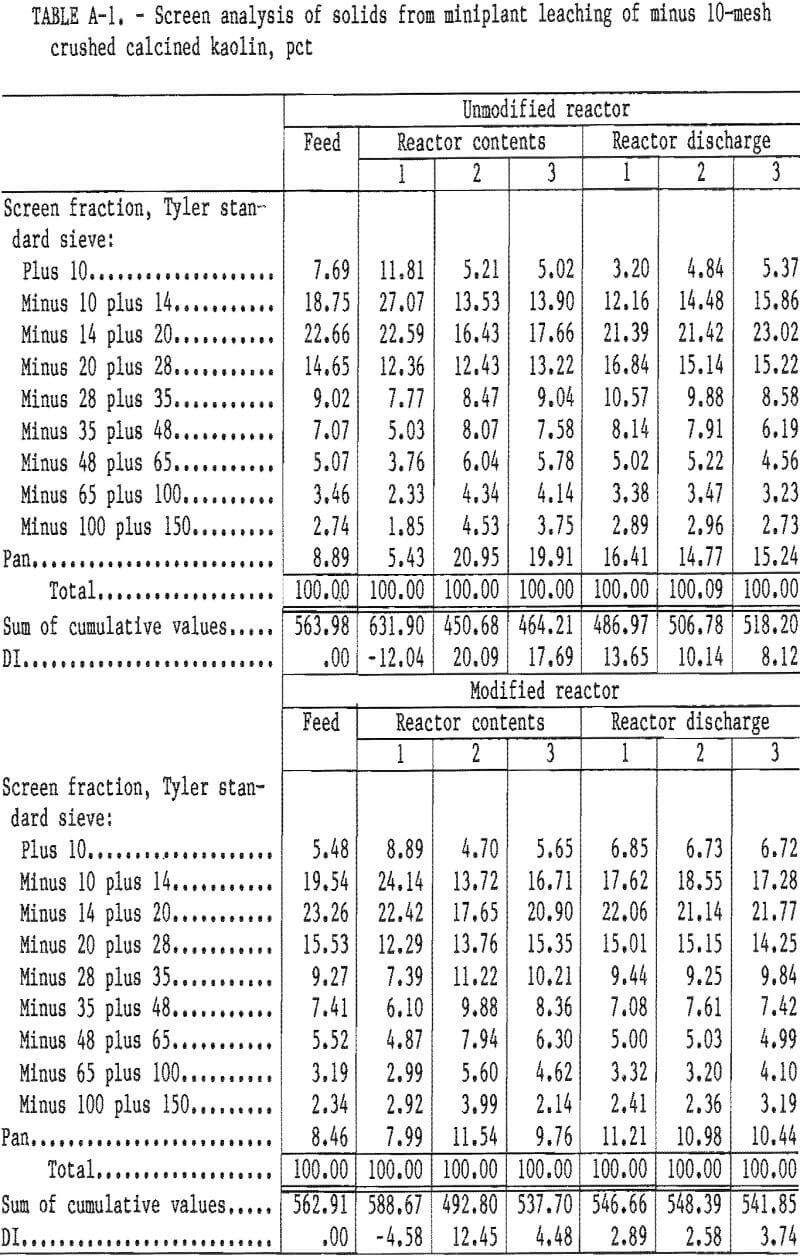
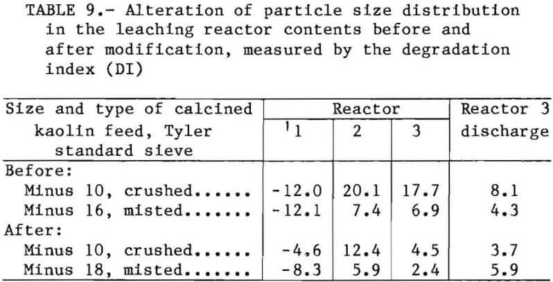
Table 9 lists the DI values for the contents of the three reactors and the discharge from reactor 3. For minus 10-mesh calcined kaolin feed, the solids in the discharge stream from reactor 3 had a DI of 8.1. Conditions in the unmodified reactors, and particularly in the first reactor, were conducive to attrition. After modification, the DI of the reactor 3 discharge solids was 3.7 and indicated a substantial decrease in attrition due to the baffling, the redesigned impellers, and the subsurface discharge of slurry from the reactor. Detailed screen analyses are provided in table A-1.
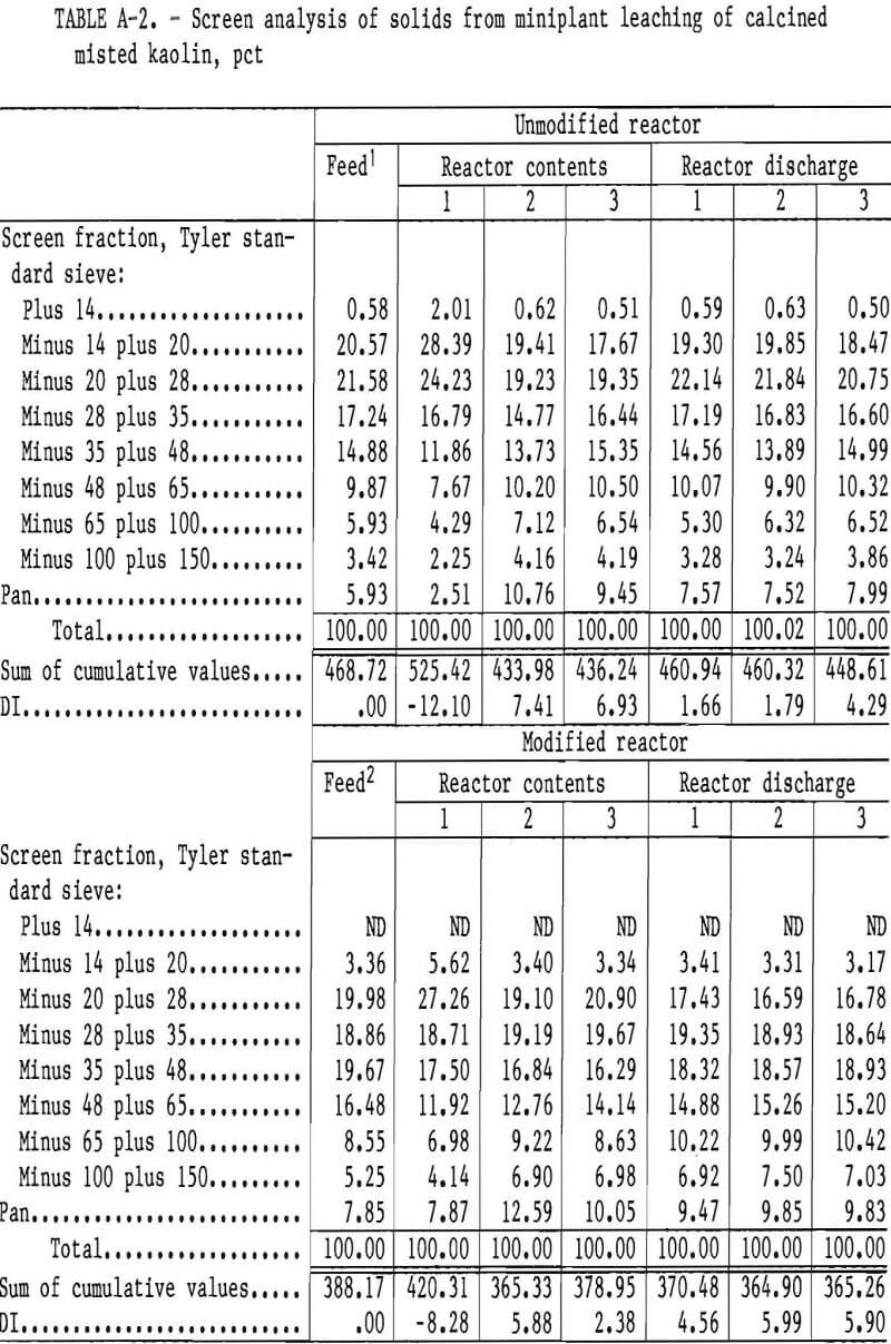
Misted feeds produced reactor 3 discharge solids with DI’s of 4.3 before modification and 5.9 after modification. This slight increase may have been caused by the difference in calcination of the minus 16- and 18-mesh misted kaolin. Misted feed generated fewer fines than crushed feed when leached in the unmodified reactors. Detailed screen analyses are given in table A-2.
DI values were negative for reactor 1 in all tests (table 9) and indicated that some classification occurred even with the minus 18-mesh misted feed in the modified reactors. Reactor modifications decreased the accumulation of large particles for both feeds and produced decreased DI values.
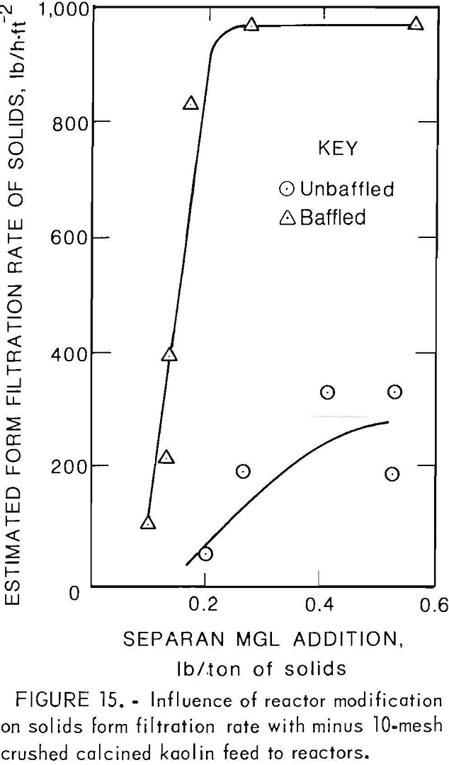
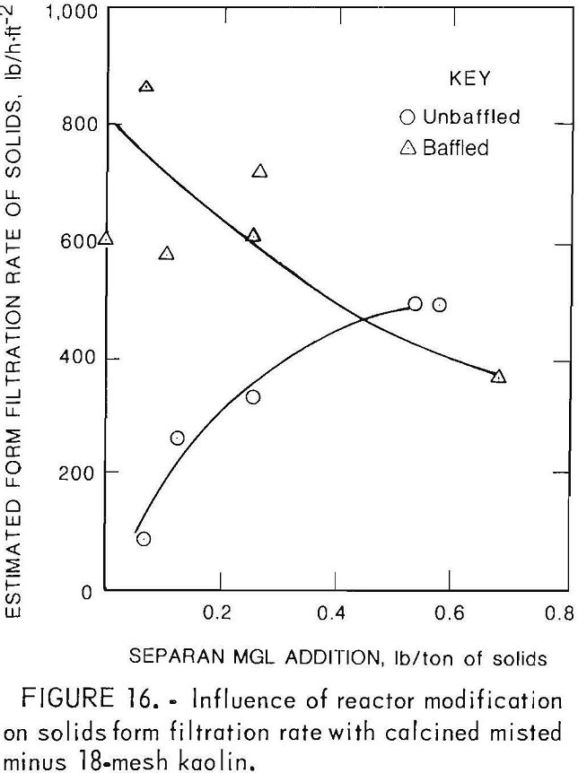
Improving the filtration rate is an important benefit resulting from decreased fines generation. Filtration performance curves were drawn that were based on the tests performed with the 10½- by 1-ft belt filter and filter feeds from leaching minus 10-mesh crushed calcined kaolin feed (fig. 15) and minus 16- and 18-mesh misted feeds (fig. 16). These curves compare the form filtration rate of solids with the flocculant addition for filter feed slurries from the unmodified and
modified reactors. Slurry from minus 10- mesh feed and unmodified reactors required a flocculant (Separan MGL) addition of 0.5 lb/ton to give the maximum solids form filtration rate of 350 lb/h·ft-². Modifying the leaching reactors increased the solids filtration rate to about 1,000 lb/h·ft-² with a flocculant requirement of 0.25 lb/ton.
Using misted feed, the unmodified reactor discharge slurry had a maximum solids form filtration rate of 500 lb/h·ft-² with a flocculant addition of 0.6 lb/ton. Misted feed slurry from the modified reactors gave a maximum solids form filtration rate of 900 lb/h·ft-² with a flocculant addition of 0.1 lb/ton.
Summary and Conclusions
Degradation of calcined kaolin particles during leaching in the 50-gal reactors of the clay-HCl miniplant was caused primarily by mechanical attrition. Chemical degradation during leaching was minor. Inadequate solids suspension by the original retreat-curve impellers and inadequate baffling resulted in the accumulation of large particles, which formed a dead space in the lower portions of the reactors, particularly in the first reactor. Autogenous grinding within this mass of particles generated excessive fines, which hindered subsequent solid- liquid separation.
Installation of a Bureau of Mines designed, custom-made impeller, improved baffling, and subsurface discharge of slurry from each reactor decreased the problems of coarse solids accumulation and formation of excessive fines. For minus 10-mesh feed, reactor modification caused the amount of solids in the first reactor to decrease from 96 to 70.9 lb, or 4.29 to 2.68 lb/gal. The solids form filtration rate on a 10½- by 1-ft continuous horizontal belt filter was increased from 300 to almost 1,000 lb/h·ft-² by the modified reactors. Increasing the filter capacity by 2 to 3 times would decrease process equipment costs, and decreasing the flocculant requirement would decrease process operating costs. Attrition of minus 10-mesh kaolin feed was decreased. Calcined misted kaolin leached in the modified reactors required the least flocculant and suggested the generation of the lowest percentage of fines. Improved reactor design increased process flexibility for treating different calcined kaolin materials.