Table of Contents
The objective of the operator of a direct reduction plant Is to optimize the cost of inputs required to obtain each tonne of DRI. Three major factors affecting the unit cost of the product are iron oxide feedstock, energy, and plant productivity.
For the past decade, most direct reduction plants have relied upon pellets as the primary feedstock for iron units. This reliance was based upon the relative unavailability and cost of high grade lump ores, the high generation of fines by many lump ores, and the belief that chemical analysis of the feedstock was the determining factor in agglomeration tendencies.
In the late 1970s, major pellet producers began to offer specially designed products for use in direct reduction processes. These pellets are normally more expensive than the blast furnace grade pellets offered by the same producers. Pellets tend to carry a premium price over the cost of iron ores because of the additional processing and the greater uniformity of product quality. However, several high grade lump ores are now available on the world market in quantity at competitive prices. This availability of a lower cost source of iron oxide of high quality has led to a renewed interest in the use of lump ores in direct reduction.
Definition of the quality of lump ores for use in direct reduction plants has been the subject of much conjecture. Because of the paucity of lump ores which had been used in direct reduction plants, researchers characterized these ores and made generalizations regarding how other lump ores and pellets having similar chemical properties would function at commercial scale. This has led to a widely held view that very stringent quality requirements must be met before an iron oxide feedstock will function properly in a direct reduction process.
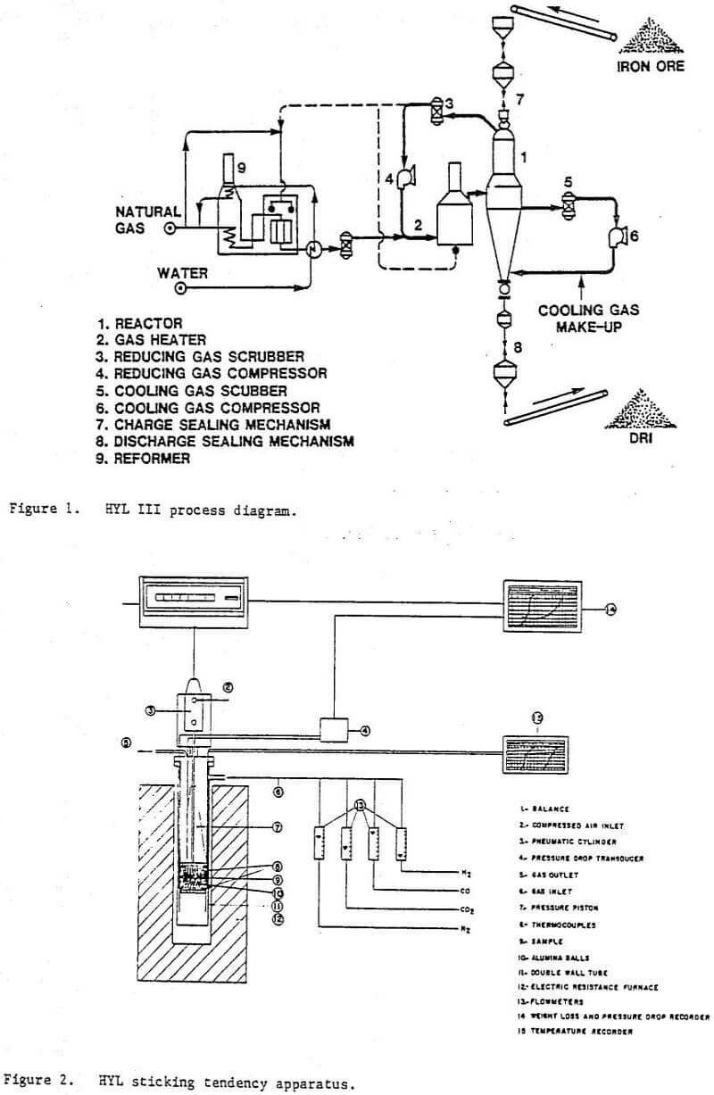
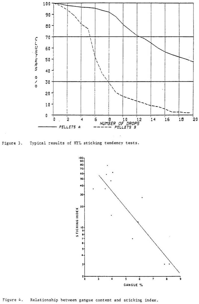
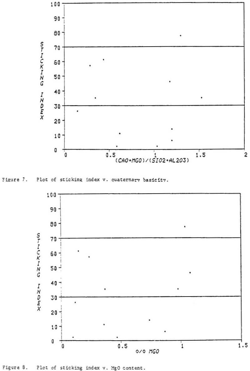
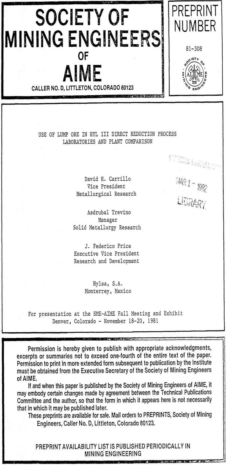
In the development of the HYL III process, one objective was to make the process adaptable to a broad range of potential iron oxide feedstocks. Numerous lump ores and pellets which are available on the world market have been tasted in the HYL laboratory to predict their response in commercial operation of the HYL III process. Many of these materials have been processed in the HYL pilot plant and in HYLSA’s commercial plant 2M5. Some of the pellets have shown undesirable sticking tendencies at temperatures above 900°C (1173 K) lamp ore has not suffered from deleterious agglomeration when processed at temperatures of 960°C (1233 K). With the addition of only 5 percent lump ore, all pellets processed at commercial scale have given fully satisfactory results at a temperature of 960°C (1233 K).
Significant improvements have been noted in plant productivity and in energy efficiency with increased temperature. Thus, the ability to process feedstocks at as high a temperature as possible is desirable because it permits a reduction in operating costs. Maximum reduction temperatures are achievable with small additions of lump material for a broad range of potential feedstocks. The HYL III process permits the operator great flexibility in choosing iron oxide feedstocks based on market conditions while enjoying the maximum plant productivity and energy efficiency which enhances the ironmaker’s ability to compete successfully in a highly competitive market.
HYL III Process Description
The HYL III direct reduction process utilizes a gas rich in hydrogen and carbon monoxide to reduce iron oxides either in pellet or lump form. The process may be adapted to utilize gaseous reductants from various sources depending on local energy costs, availabilities, and future supplies.
Basically, an HYL III plant consists of three sections:
- Reducing gas generator
- Reduction unit
- Auxiliary services
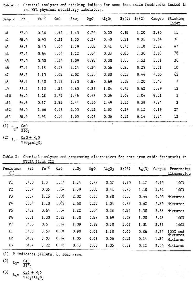
Figure 1 is a diagram of a typical HYL III plant.
Reducing Gas Generator
The reducing gas generator, when utilizing natural gas as the reductant source, is a standard chemical process industry gas reformer using the steam-methane reaction over a commercially available nickel catalyst.
Reduction Unit
The central element of the reduction unit is the reactor which is divided by the gas flow dynamics into three separate zones: reduction, isobaric, and cooling. The reactor operates at a pressure of approximately 5 kg/cm² (490 kPa).
The reduction loop comprises the reduction zone of the reactor, a direct contact gas scrubber, a compressor, and a gas heater. Some of the spent reducing gas is removed after passing through the scrubber and is used as a fuel for the reducing gas generator and heater. The reducing gas flow within the reactor is countercurrent to the solids flow. The interface of the gas generation section and reduction loop is the injection of recently generated gas into the reducing gas loop just before the gas heater.
The cooling loop is composed of the cooling zone of the reactor, a direct contact gas scrubber, and a compressor. The interface of the gas generation section and the cooling loop is the injection of a small amount of fresh gas into the cooling gas loop just before the cooling zone of the reactor. In addition to cooling, carbon deposition in the reduced product occurs in the cooling zone. Gas flow in this zone is also countercurrent to the solids flow.
Operation of the reactor at high pressure is made possible by HYL’s patented pressure seal and solid flow mechanisms. These mechanisms permit continual charging and discharging of the reactor with negligible loss of internal pressure, reducing gas, and heat. The product is discharged in a cool, stable state at a temperature of approximately 50°C (323 K) with no requirement for passivation prior to long term storage or shipping.