
After considerable experience in connection with the magnetic iron-ores at the South, especially in the Cranberry district of western North Carolina and eastern Tennessee, the writer was led into a thorough investigation of the magnetic separation of iron-ores, and, from this investigation, has gradually been developed a separating machine which it is the purpose of this paper to explain.
Numerous United States patents have been issued upon machines for magnetic separation. Since the original patents, it is not possible today to establish broad claims upon the principles of electro-magnets as applied in such machines. Among these inventions there are certain types of separators which have very marked practical advantages over the others; and these successful machines, while varying radically from each other in their proportions and arrangements, are all based upon a principle originally explained in a patent which was granted, and which has now expired by limitation.
The problem of practically separating iron-ores, as found in the mines, is very different from the separation of a purely magnetic substance from a purely non-magnetic one, since the crystals of magnetite, scattered through the ore-bearing rock, and sometimes collected in masses, are of very different sizes. The average size of the particles may be definitely ascertained for each mine, and the crushing- and screening-machinery may be adapted thereto, but there will still be a large percentage of very fine crystals which, in the crushing for the average, will not be broken apart from the gangue. If these mixed particles are thrown into the heads they carry gangue with them, and if thrown into the tails they occasion a loss of iron-ore. There are two methods for preventing such loss. One is, to crush all the material to the size of the finest particles, which means, of course, a large crushing-plant, heavy wear and tear, and excessive cost for repairs, and the production of only a very fine-grained concentrate which our blast-furnace managers, to say the least, do not ardently desire. The other, and only practical method, is to crush at first to a comparatively coarse size, determined by the character of the material, and to separate immediately upon a machine which has a power of selection, and which will throw off a first-grade of tails, containing practically no magnetite, then a second tails or middlings, with iron in the mixed particles, then a third (and if necessary, a fourth, etc.) division, and finally, a practically pure magnetite as heads. The first tails go to the dump, the heads, comparatively coarse, are sent at once to the bins or cars, and the second and third or other tails, which may amount, perhaps, to one-fourth of the crude material, are re-treated on a second separator, and such portions of them as may require it, are crushed sufficiently fine to break the magnetite from the gangue. The fine crushing of three- fourths of the product is thus saved, and the cost and wear are correspondingly reduced, while the concentrates contain mainly coarse particles. These facts have been appreciated for many years by those skilled in the art; but the mechanical and electrical difficulties in the designing of practical machines were deemed by many to be insurmountable. There are, however, now on the market, as already remarked, a number of forms of separators which act on this principle, and are excellent machines, each protected by special patents.
The machine which is the subject of this paper is one of these. In designing it we have endeavored to keep in mind the essential requirements for machinery subject to rough usage, viz. (in addition to efficiency and economy of operation) durability, simplicity of design, and convenience for replacing quickly by ordinary unskilled labor any disabled parts—considerations which apply as well to magnetic separators as to other machinery connected with mining.
This machine has grown out of the original Lovett-Finney magnetic separator, which has been running successfully at Weldon, N. J., for eighteen months or more. We have retained the features of simplicity and low cost for repairs which distinguished that apparatus, but have changed the form and the electrical arrangement, and have added other magnetic parts which essentially modify the action of the separator and the character of its products.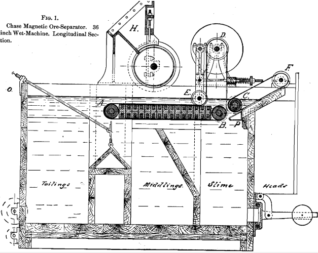
The present form of the magnetic wheel is a solid soft-iron roll of small diameter (4 inches or less), and of any desired length (usually 3 feet), in which two helical grooves of about 1 square inch section are cut. In these are wound coils of continuous copper wire or ribbon. There being two spiral grooves (constituting, in fact, simply a double-threaded screw), the wire carries the electric current in each groove in the opposite direction from that of the current in the adjoining groove, so that a magnetic circuit is set up which converts the screw thread into continuous helical poles of opposite polarity, and forms, with a minimum amount of iron, copper, and cost of manufacture, a magnet of extraordinary strength, with a continuous field of magnetic force all over its circumference. A thin, drawn-brass tube is slipped over this roll, protecting it from injury, without impairing its properties as a magnetic wheel, equally efficient per square inch of surface whatever the length of the roll may be.
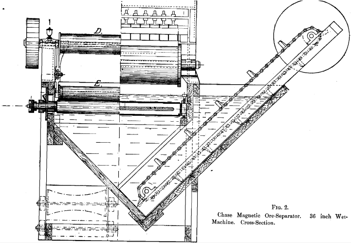
In the Chase separator, as shown in Figs. 1 and 2, there are three of these magnetic rolls, A, B, and C, Fig. 1. The function of the first roll is to separate a wholly non-magnetic grade of tails from the remainder of the material treated. As the crude material is fed upon a belt, which approaches the wheel horizontally, the necessary consequence is, that every particle of magnetic oxide of iron comes immediately within the scope of the magnetic field, and cannot escape until carried by the rotation of the roll around to its under side, while the non magnetic tails fly off tangentially.
The pure magnetite, the mixed particles, and a considerable amount of non-magnetic dust, all cling together to the belt against the under side of the roll, and are passed on by the movement of the belt to the first of a series of horizontal magnetic poles. These are “consequent poles,” developed by winding a soft iron yoke alternately in opposite directions, and inserting between these windings soft iron bars to form the poles. A tumbling motion is immediately set up in the mass; the middlings drop quickly into their receptacle; the fine dust continues further, but falls also into its receptacle, while the pure magnetite passes along under all the poles and is delivered by the last of these to the second magnetic wheel, B, which whisks the magnetic particles around the sharp corner, freeing them from the last grains of dust by this movement, together with the action of a blast of air or of water from the pipe P. The second wheel, B, delivers the magnetite to the third or picker-wheel, C, over which runs the second belt, which carries the magnetite to any desired point. The letters in Figs. 1 and 2, besides A, B, C and P, already mentioned, indicate the following parts: D, driving- pulley ; E, tightener-pulley; F, non-magnetic rolls, delivering “ heads; ” H, feed-hopper and feed-wheel; O, overflow.
The separator is simple in its construction and cheap to build. Its wearing parts consist of the bearings for the shafts, and the cheap , cotton-duck belt, which receives all the wear from the ore, enduring,
by reason of its softness, as wax does before the sand blast, the blows which would cut rapidly into a harder and stiffer material. These belts have been in use for eighteen months upon the separator at the Weldon mine, in New Jersey, and have demonstrated their durability under these conditions.
The merit of this design is mainly in the comparatively small rolls and the short distances between the magnetic poles, which are never increased, however wide and correspondingly capacious the machine may be. The winding of the magnetic rolls in double spiral with continuous spiral poles gives a magnetic field of equal efficiency whatever the length or diameter of the rolls, and the winding of the intermediate magnet is such that it is exactly as efficient per square inch of surface whatever the width of the machine may be. There is, therefore, no limit to the width of the machines, except such as may be set by mechanical considerations.
The length of the separator depends entirely upon the length of the intermediate magnet, which decides the number of “tumbles” of the stuff, and thereby the quality of the concentrates. This may vary with different ores and degrees of fineness of crushing.
Very interesting facts in connection with electro-magnets of these irregular forms have been brought out in our experiments; and as the matter is one of considerable importance, involving the substitution of another unit of measurement in place of that now in general theoretical use, I feel justified in going over ground already familiar to many. As we all know, an electric current, passing along a wire, creates around that wire, through the air, in planes at right angles to the direction of the wire, a magnetic current, or series of magnetic currents, the quantity of which depends upon the quantity of the electric current. If a bundle of wires be used, the quantity of the magnetic current round about the bundle is proportional to the total amperes of the electric current flowing through the wires; and, taking a unit width of this magnetic circuit (say one inch, or one centimeter), the total magnetic “flux” through a cross-section of this width will be measured exactly by the total amperage in the bundle of wires; i.e., the number of wires times the amperes in each. If this magnetic current flowing round about this bundle of wires be allowed to pass through soft iron, it becomes vastly increased, the soft iron acting as a good conductor for the “ lines of force.” This increase is represented in theoretical calculations by a constant μ, which expresses the relative conductivity of iron and air for magnetic lines of force. This constant varies with the quality of the iron, growing less with harder irons, especially with the increase of carbon and manganese, and also less as the iron in question approaches its “ point of saturation,” by which is meant the maximum number of lines of force that can be driven through a unit section of it. In nearly all electrical winding today the cores of soft iron are of circular section, and the wire is in continuous turns about the core, so that the term “ ampere-turns ” has come to be accepted as a reliable measure of the magneto-motive force, and hence of the number of lines of force passing through the core.
The design of irregular forms of magnets like the H-section and spirally-wound wheel, already described, has compelled us to look for another basis of measurement, as “ampere-turn” is not applicable to the spiral winding; and we have thus been led to see that too much emphasis has been laid upon the “ ampere-turn ” in theoretical laws and formulae, and that the term “ turn ” has received, in this connection, a special significance which it should by no means have. There is absolutely no advantage in a completed circle over the same length of straight wire for the creation of magneto-motive force, and therefore a “ turn ” merely represents a certain length of wire. It is true that the total turns multiplied by the amperes passing in each wire gives the total amperes at work upon the magnet, and this is properly a measure of the magneto-motive force which compels the magnetic current to flow through the iron from one pole to the other, and return through the air outside the coil of wire. The quantity of the magnetic current (technically, the magnetic “ flux” ) depends also upon the magnetic resistance of the circuit, which varies directly as the length of the circuit, and inversely as its cross-section. It is evident that the circle is the best form of section for a core, as it gives the greatest area for a given periphery, and therefore the least magnetic resistance for a given length of wire, of all sectional forms. So long as we are considering a core of circular section, the use of “ ampere-turns ” is correct, as the outer turns about make up for their increased distance from the iron, by their increased length of circuit. This fact in itself shows that it is the length of the wire, together with its nearness to the iron core, which is of real importance, and not at all the idea of a complete turn. When we consider our spirally-wound magnet, with its continuous helical poles, which are induced only by straight wires on one side carrying electric current in one direction, and by straight wires on . the other side carrying current in the opposite direction, we are forced to drop the term “ turns ” out of sight entirely, and use only the total length of wire in a unit-length of coil, which gives, when multiplied by the amperage of the electric current, a proper measure of the magneto-motive force generated in a unit-length of the core beneath measured in the direction that the wires run. The magneto-motive force divided by the magnetic resistance, gives the magnetic flux or total number of lines of force, and thus practically the strength of the magnet under consideration. The point of all this extended explanation is, that for “ampere-turn” the terms “ampere- inch ” and “ampere-centimeter” should be substituted, inasmuch as the latter terms are applicable to all forms of magnet coils, while the former is only applicable to a certain special case.
I have noticed this point at some length because, in designing machines involving magnets of irregular forms, one may be thrown off the track by reason of the circumstance that all the theoretical teaching, including the books upon the subject, has proceeded from the study of electro-magnets with cores of circular, or nearly circular, section ; and, therefore, all measurements, laws, and formulae have been based upon the ampere-turn, which we have found to be, for the conditions of our irregularly formed magnets, radically wrong.
In all such problems, however, the supreme test is that of actual trial, which develops, in spite of all the theories influencing the preliminary design, faults which can be remedied only by gradual elimination. It is from experience, and not in obedience to any theory, that we have learned to design magnets which are decidedly “stubby ;” that is, have very short magnetic circuits, short poles with not too great distances between them, and a maximum amount of current, which is obtained by winding with ribbons of copper instead of round wires, thereby increasing the amount of current and decreasing the voltage, and therefore the tendency to leak, short-circuit, or burn out.
The main commercial objects of magnetic separation are, first, the diminution of the amount of earthy gangue, with a consequent increase of the percentage of metallic iron in the product, and, second, the incidental elimination of phosphorus (usually present in apatite), and often of sulphur or titanium. A crude ore, carrying about 30 per cent, of iron, and reasonably coarse in structure, can be concentrated to 66 or 68 per cent, very readily. The loss of iron as magnetic oxide in the tails, in practical everyday running, will not exceed 3 to 4 per cent., while the total loss in the tails will depend upon the amount of iron present in the crude material in a non-magnetic state, such as the sesquioxide, silicates, and sulphides, though each of these may be at times somewhat magnetic, the sulphides especially, one variety of which, pyrrhotite, is notoriously so.
There is a general protest from all magnetic-separating experts against the usual method of judging results by percentages of metallic iron. Every one familiar with the subject through actual practice appreciates the misleading nature of this test in comparing results from different separators working on different ores. Especially is this true with regard to the loss in tails. Some rich ores leave, after separation, a very small amount of tails, so that a relatively minute quantity of iron lost may yet make a large percentage in the scanty tailings, while low-grade crude ore of the same mineralogical character and physical texture may, on account of the greater bulk of the tails, present, apparently, a much better showing in percentage of loss. The only proper way, in such comparisons, is to determine the percentage of magnetic oxide saved, and the percentage lost, out of the original amount in the crude ore. This gives a basis for comparison, as to the efficiency of the machinery and its adjustment, which is not misleading.
For instance: An ore carries 38 per cent, of metallic iron in the crude, of which 3 per cent, is in silicates (hornblende), the other 35 per cent, corresponding to 48.3 of magnetic oxide of iron. In examining the results of separation, we find that the heads compose one-half of the original material by weight, and carry 67 per cent, of iron, or 92.5 of magnetic oxide, equal to 46.3 out of the original 48.3 in the crude ore, while the tails contain the remainder, which is 2 per cent, of magnetic oxide out of the original 48.3 in the crude material; but this 2 per cent, is 4 per cent, of the weight of the tails themselves, which have only half the weight of the original material. In this case direct analyses of the tails would show 4 per cent, of magnetic oxide, equal to 2.896 of metallic iron, and also 6 per cent, of iron from the silicates, which, as the weight is only one-half, would be doubled in percentage, or a total of 8.896 per cent, in the tails. Yet there has been, in reality, only a loss of the original 3 per cent, of iron in the silicate and 1.448 of the original 35 of metallic iron, or 4.448 in both. This discrepancy between the apparent and the actual results is the greater, as the proportion by weight of the tails compared with the crude material is less.
After all is said, it still rests with the crushing and granulating part of the plant whether there be a financial success or failure. In nearly every case the crushing costs from four to five times as much as the magnetic separation, and requires, moreover, the greater part of the original cost of installation.. It is for this reason that we believe that a separator, which will relieve the crushing-plant of a considerable portion of its work,—thus permitting the use of a smaller plant for a given aggregate product, and greatly lessening both the initial outlay and the cost of current repairs, and which accomplishes this result by its ability to divide the coarsely-crushed mass of crude material into various distinct grades, each of which may be specially treated afterwards, according to its needs,—must be a factor of great importance in the problem of magnetic separation.
Another important point in favor of this machine is its adaptability to wet separation, by which I mean, to the treatment not of partially wet or damp material, but of material which is acted upon by the alternating-poles when wholly below the surface of water. The action in this case is the same as in air, with the additional advantages of the solving and washing effects of the water, as well as the diminution of gravity of the particles, which fall more slowly from the belt. For separating very dusty ores, the use of water is indeed essential, especially when the fine dust is, in considerable part, apatite, which is liable to cling to the magnetite and, in the dry process, to be carried into the heads in spite of strong air-blasts. Under water, there is no tendency on the part of any earthy minerals to cling to the magnetite; all the dust is washed off immediately, and the heads come out in a thoroughly cleansed condition, carrying 2 or 3 per cent, more iron, and considerably less phosphorus, than by the dry process.
The separator here described can be operated either wet or dry, without other change (for the latter purpose) than draining off the water from the tank and attaching an exhaust-fan. When specially constructed, however, for dry work, the frame and arrangements are somewhat modified.
As I remarked at the outset, the machine has grown up naturally and gradually out of a very careful study of the whole subject, and especially after examination, on the ground, of nearly all the notable separating-plants in this country, an investigation which convinced the writer that there was still abundant “ room at the top” for a new and practical separator. Its success is largely due to the co-operation of Mr. Axel Sahlin, the engineer of the International Ore- Separating Company, to whose ability and experience the credit should be chiefly ascribed for the mechanical compactness and simplicity of the large machines.